97658 OEM Replacement Boost Tubes for 2013+ Dodge 6.7L Cummins (24-valve) ISB Pickup Trucks (2500/3500)
INSTALL INSTRUCTIONS
Part #s
25992, 25994, 25995, 25996
OEM Replacement Boost Tubes
2013+ Dodge 6.7L Cummins (24-valve)
ISB Pickup Trucks (2500/3500)
Please read through the following instructions thoroughly before starting your installation. If you have any questions please visit our Support Page.
SECTION 1
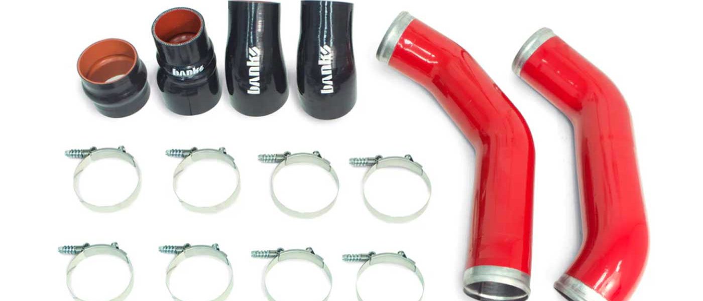
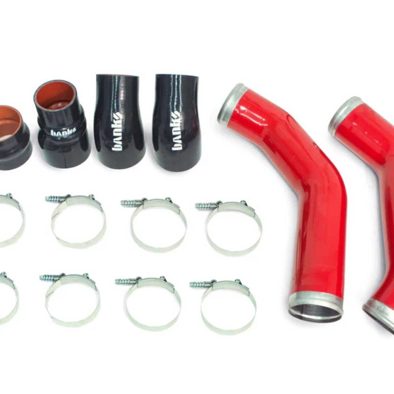
What’s Included
General Assembly for Kits 25992, 25995
General Assembly for Kits 25994, 25996
Tools Required
• 3/8 Drive ratchet w/ extension
• 3/8 Drive Inch and metric deep sockets
• 5/16” or 8mm Nut Driver
• Pliers
• Flat blade screwdriver
• Vehicle Lift and support stands or Floor Jack and Jack Stands (home install)
Highly Recommended Tools
• Foot/ pound torque wrench
• In/ pound torque wrench
General Installation Practices
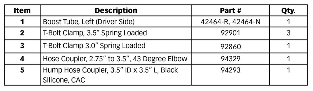
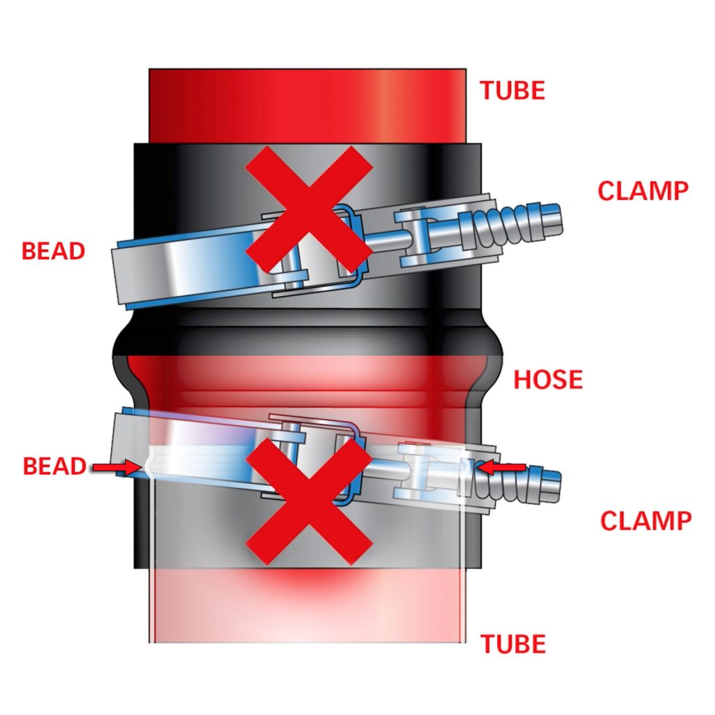
ATTENTION: Boost-Tube Clamps
When Installing the clamps, be sure the hose and clamps go on far enough to clear the bead on each end.
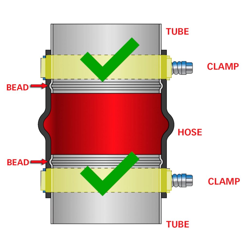
An improper installation, such as a clamp sitting directly on a bead or crossed diagonally, will result in a boost leak.
SECTION 2
Remove Air Box and Fender Liners
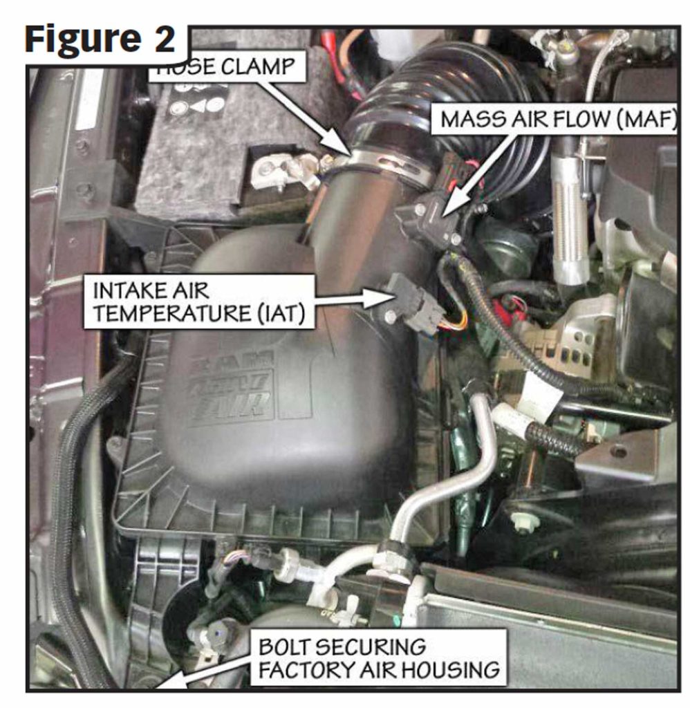
1. Remove the bolt, using a 13mm socket, from the radiator core support that secures the factory air housing. See Fig 2.
2. Loosen the hose clamp to the stock intake tube attached to the air housing.
3. Slide the red locking mechanism up on the Mass Air Flow (MAF) sensor connector. Press the tab on the connector and remove the connector.
Press the tab on the Intake Air Temperature (IAT) sensor connector and remove the connector. Pull the plastic anchor holding the wiring harness to the air housing lid and move the harness out of the way.
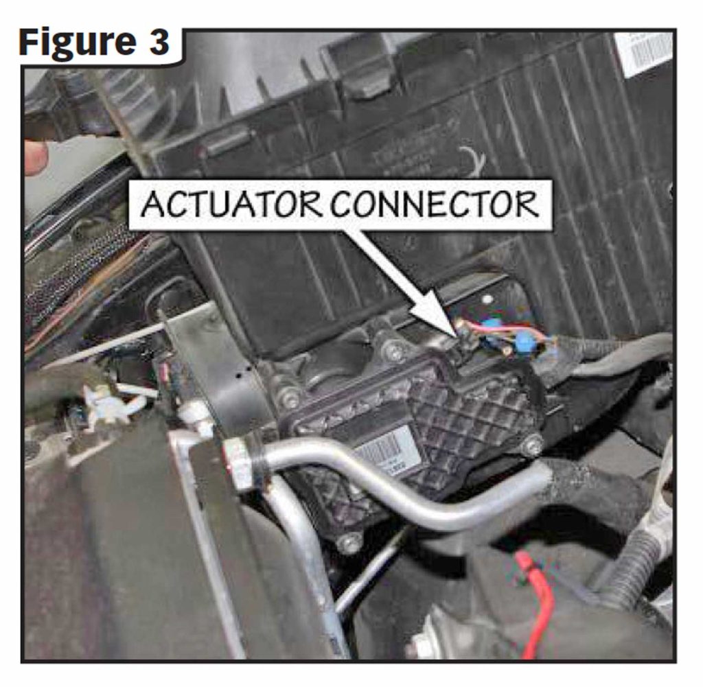
4. Lift the air housing up and partially out of the engine compartment to gain access to the Ram Active Air® actuator connector on the actuator motor on the side near the bottom of the housing. Be careful not to pull the housing up too far to damage the wiring harness. Once the housing is pulled out enough to gain access to this connector depress the tab on the end of the connector and disconnect the connector from the motor. The housing can now be removed completely from the vehicle. See Fig 3.
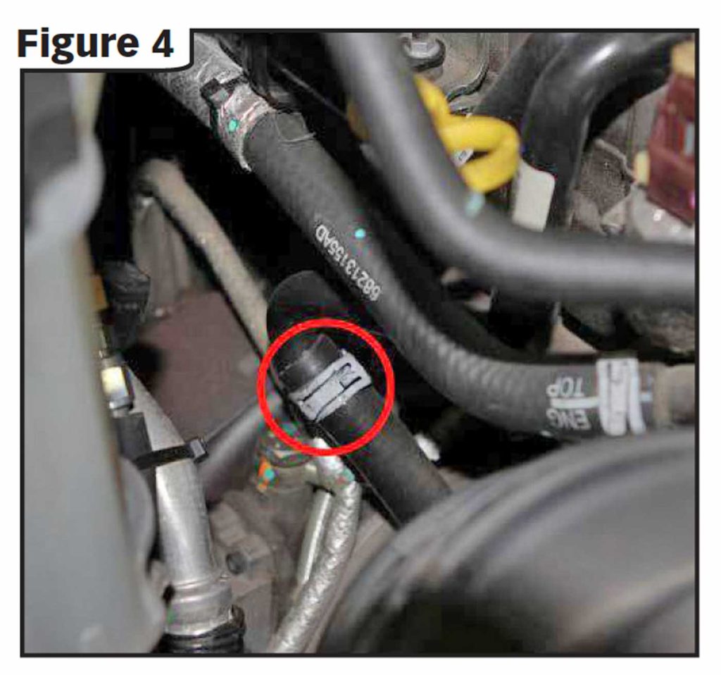
5. Locate the spring clamp retaining the PCV hose (See Figure 4). Using appropriate pliers loosen the clamp and slide it up over the metal tube and out of the way. With the clamp out of the way, pull the hose to disconnect from the metal tube.
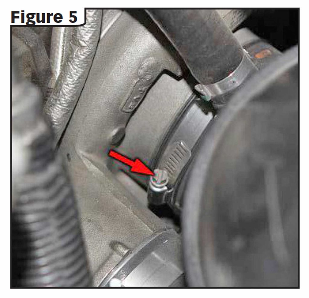
6. Loosen the hose clamp holding the intake tube to the turbo inlet and remove the intake tube from the vehicle (See Figure 5).
Remove Driver & Passenger Side Fender Liners
1. Lift and support vehicle.
2. Remove both front wheels and tires.
3. Remove all the 8mm hex head screws holding the fender liners in place.
4. Carefully pull the fender liners out.
SECTION 3
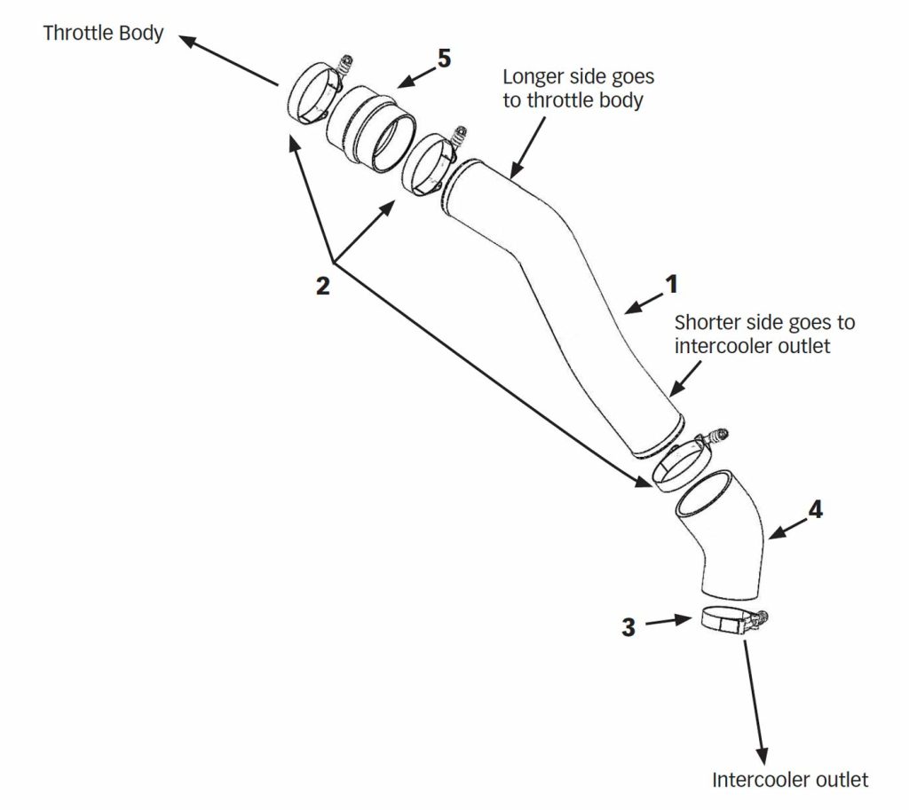
Install Driver Side Boost Tube, 42464 or 42464-N
1. Use a 7/16” deep socket to loosen the two clamps holding the boost tube to the throttle body and intercooler outlet. Pull out the tube and discard the clamps.
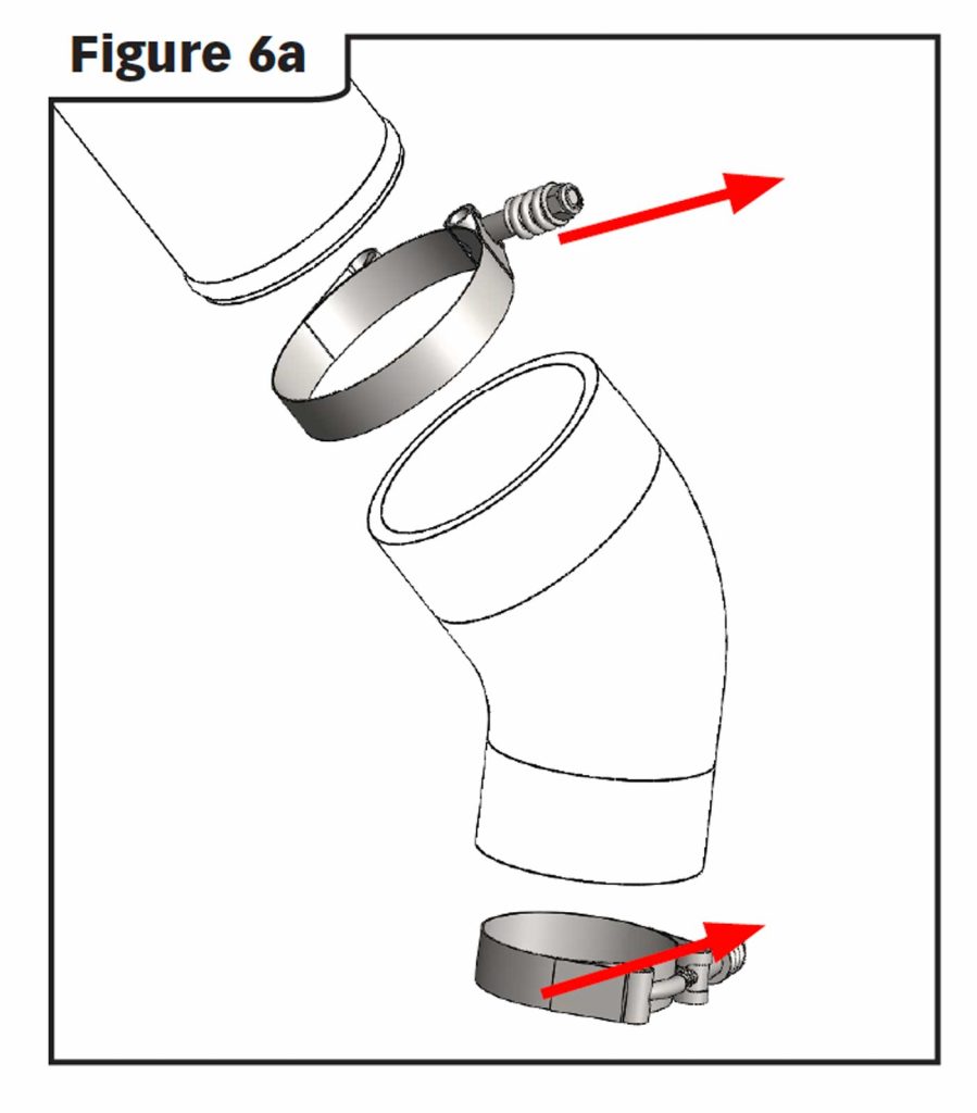
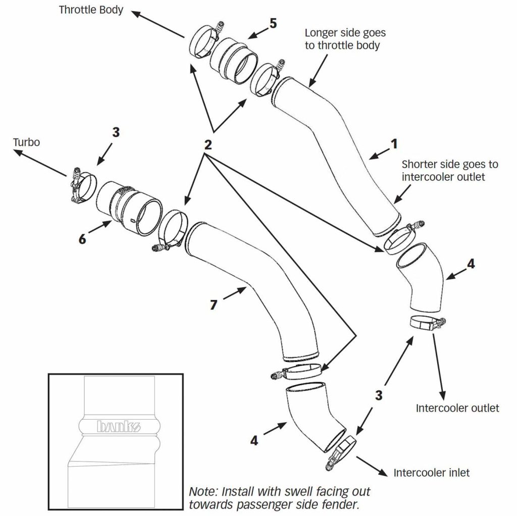
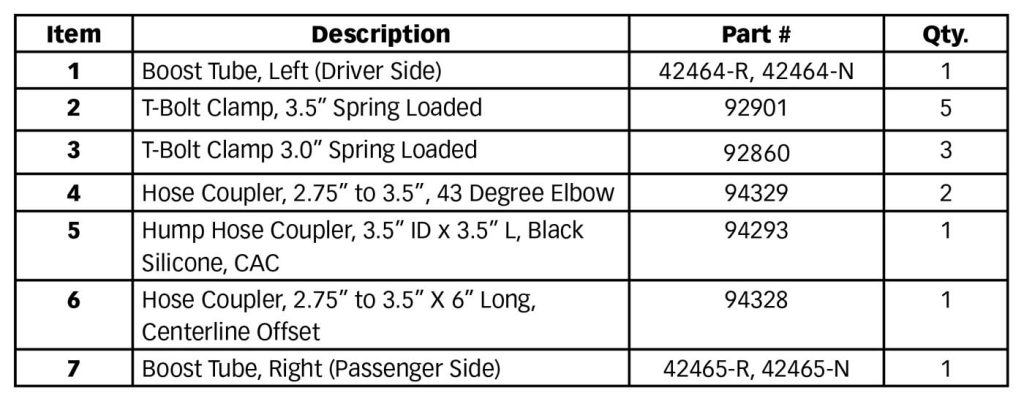
2. Using Figure 6a, slip the 2 T-Bolt Clamps (6 &7) onto the elbow hose coupler (4) and install them onto the intercooler outlet. (also see Figure 1)
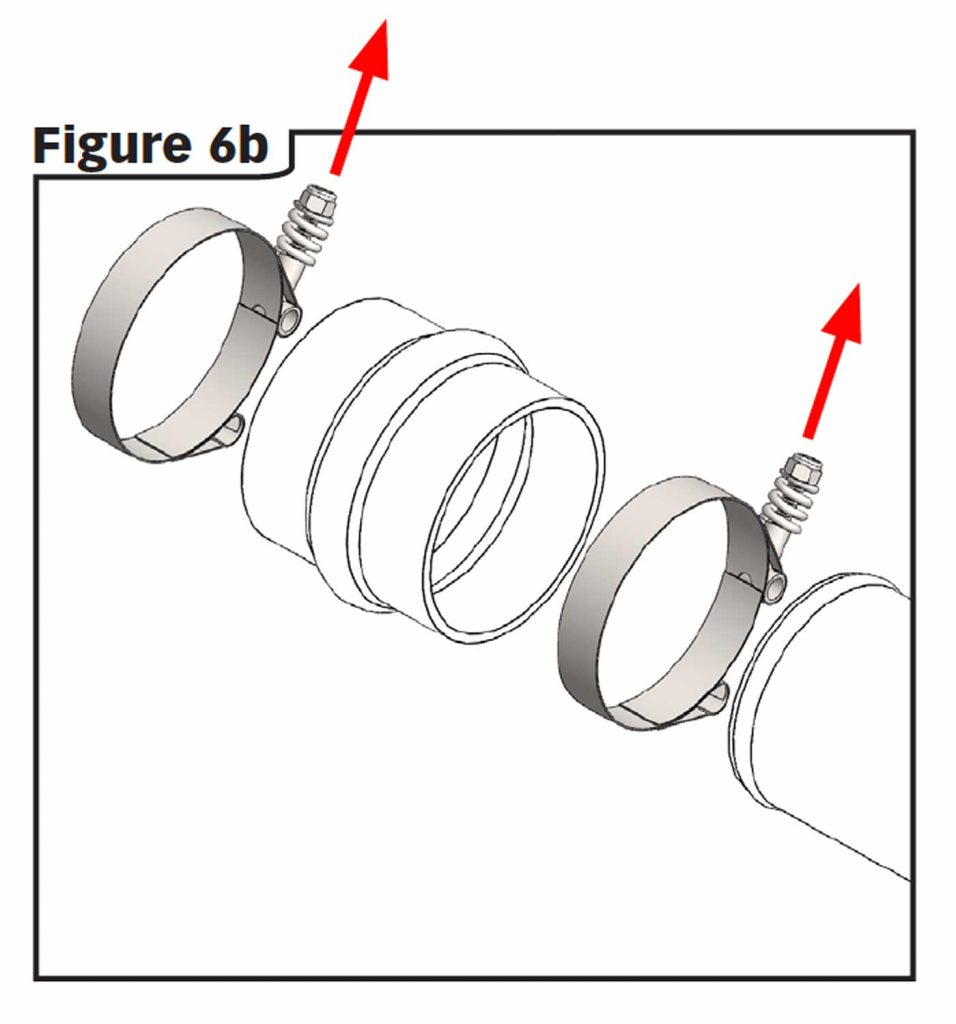
3. Using Figure 6b, slip the 2 T-Bolt Clamps (6) onto the straight hose coupler (5) and install the appropriate end on the driver-side Boost Tube. (also see Figure 1)
4. Install the Boost Tube into place and torque hose clamps to 5 ft.-lbs (60 in-lbs).
SECTION 4
INSTALL PASSENGER SIDE BOOST TUBE, 42465 OR 42465-N
Note: Skip to section 5 if installing kit 25994 or 25996 (Driver side tube only)
1. Use a 7/16” deep socket to loosen the two clamps holding the boost tube to the turbo discharge and intercooler inlet. Pull out the tube and discard the clamps.
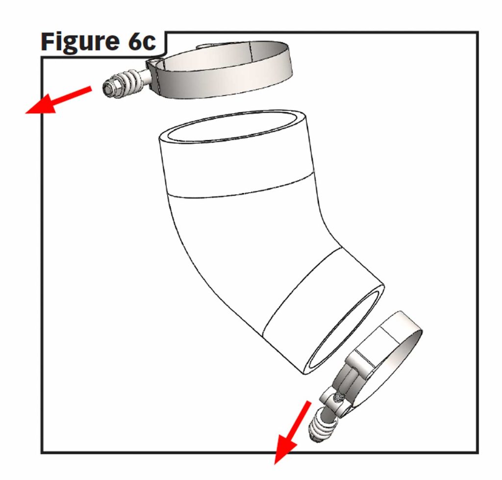
2. Using Figure 6c, slip the 2 T-Bolt Clamps (6 & 7) onto the elbow hose coupler (4) with the correct orientation and install onto the intercooler inlet. (also see Figure 1)
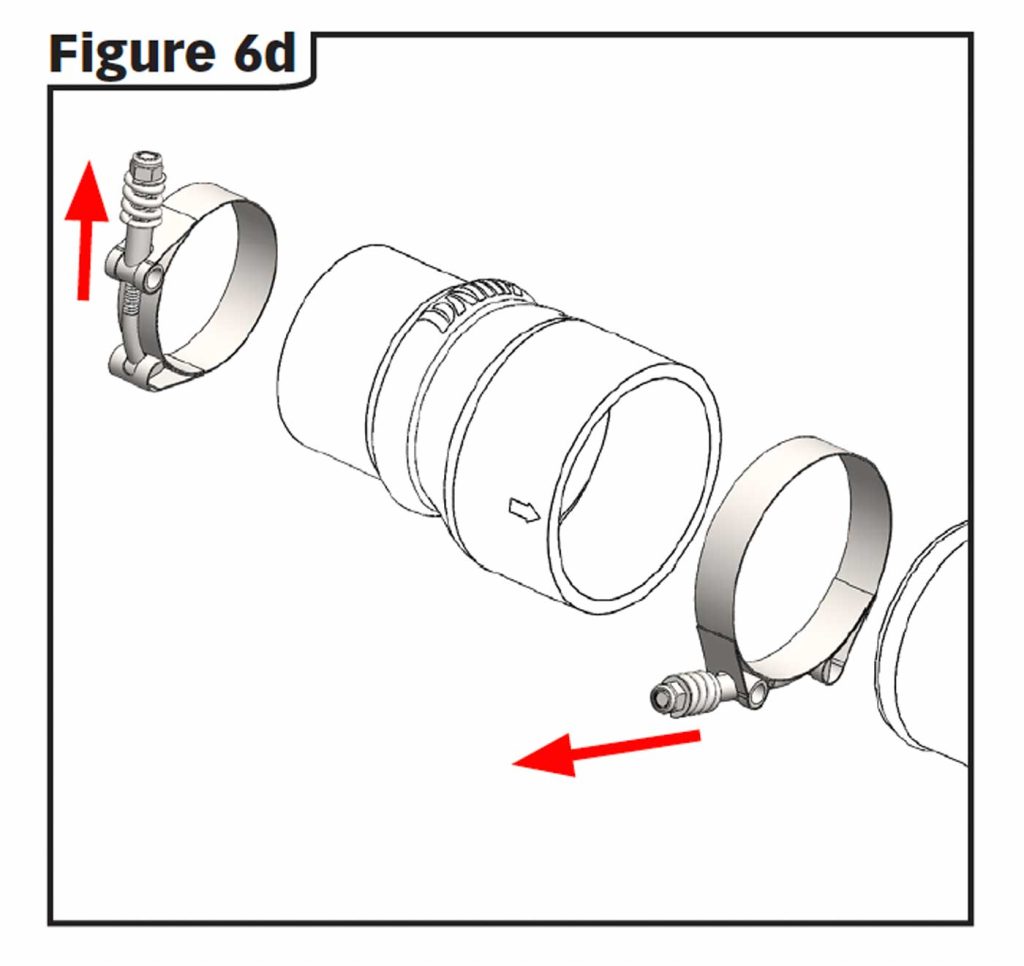
3. Using Figure 6d, slip the 2 T-Bolt Clamps (6 & 7) onto the transition hose coupler (3) and install the coupler onto to the appropriate end on the passenger side Boost Tube. Make sure that the swell on the coupler is pointing out away from the vehicle. (also see Figure 1)
4. Install the Boost Tube into place and torque clamps to 5 ft.-lbs (60 in-lbs).
SECTION 5
REINSTALL THE FENDER LINER
1. Push the fender liners in place.
2. Reinstall the 8mm hex head screws.
3. Reinstall the wheels and tires.
4. Lower the vehicle.
REINSTALL THE AIR BOX
5. Install the intake tube onto the turbo inlet.
6. Reinstall the PCV hose and clamp.
7. Drop the air box in place and reconnect the Ram Active Air® actuator connector.
8. Push the air box into place making sure that the two pins on the bottom of the air box pop into the grommets.
9. Adjust the intake tube and slip it into the intake filter.
10. Tighten all the intake clamps.
11. Reconnect the MAF and IAT sensor connectors and secure them.
12. Tighten the front intake bolt using the 13mm socket.
13. Reconnect the negative (ground) cable to the battery (or, batteries).

14. Your system includes two Banks Power decals (8) designed to complement the Dodge Cummins Turbo Diesel emblem on your truck. Use the provided measurements to position the logos for a clean factory look.