96793 Techni-Cooler System for 2013-18 Dodge 6.7L Cummins (24-Valve) ISB Pickup Trucks (2500/3500/4500/5500)
INSTALL INSTRUCTIONS
Part #s
25987, 25989
Banks Intercooler System 2013-2018 Dodge 6.7L Cummins (24-Valve) ISB Pickup Trucks (2500/3500/4500/5500)
Please read through the following instructions thoroughly before starting your installation. If you have any questions please visit our Support Page.
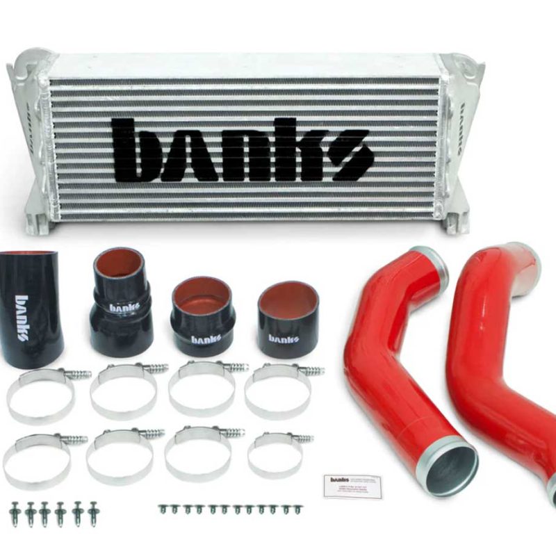
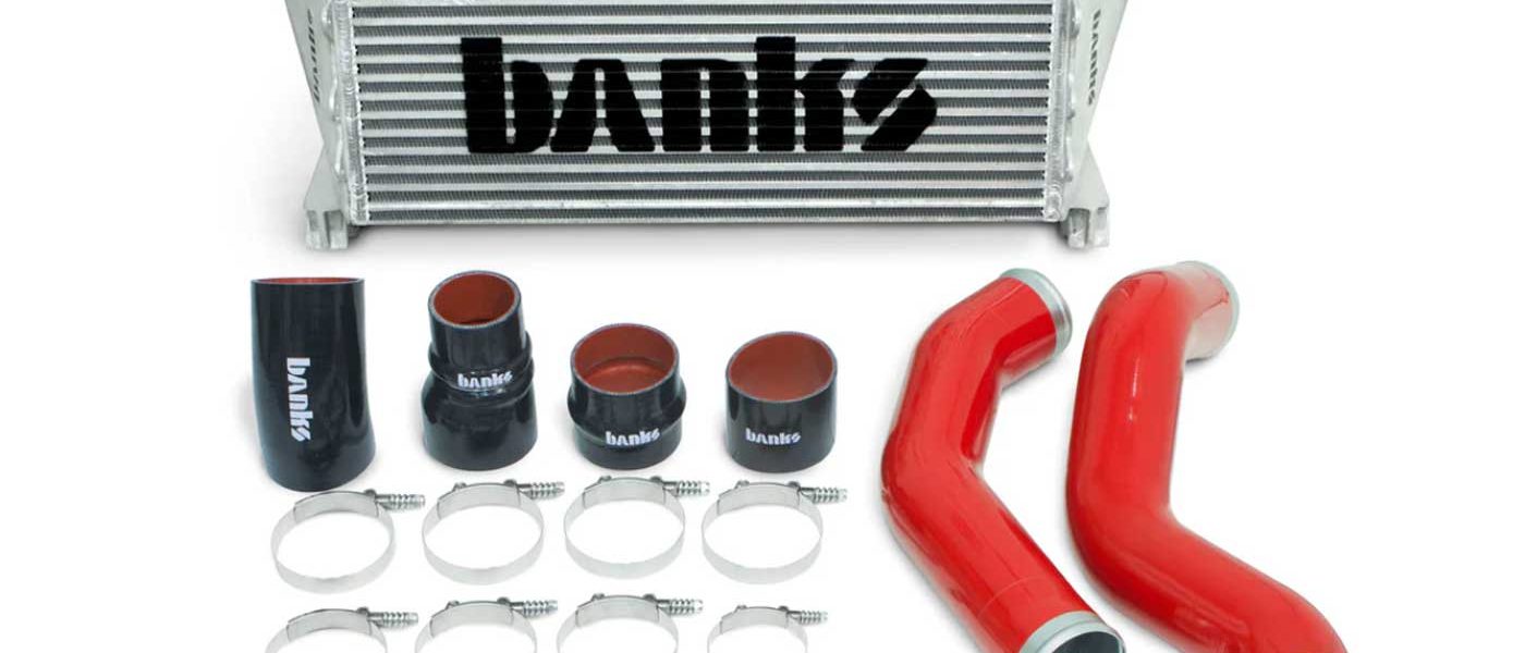
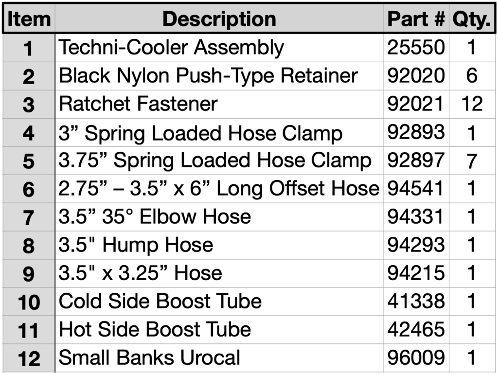
What’s Included
Tools Required:
• 3/8 Drive Ratchet
• 3/8 Drive Ratchet Extensions
• 3/8 Drive Inch and Metric Deep Sockets
• Flat blade screwdriver
• Vehicle lift and support stands or floor jack and jack stands (home install)
Highly Recommended Tools:
• Metric combination wrench set
• 3/8 Drive swivel attachment
• Panel clip removal tool, or needle nose pliers
• Hack saw with fine tooth blade
• Tape measure
• Straight edge or steel ruler
• 1/4 Drive drill motor
• 1/4″ Drill bit
• Red or silver ink marker
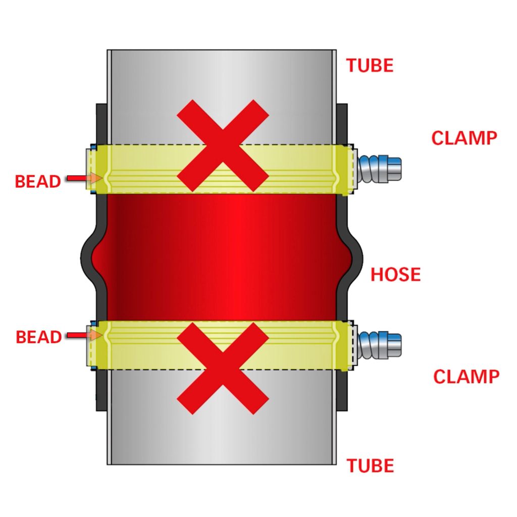
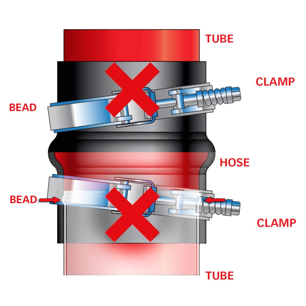
ATTENTION: Boost-Tube Clamps
When Installing the clamps, be sure the hose and clamps go on far enough to clear the bead on each end.
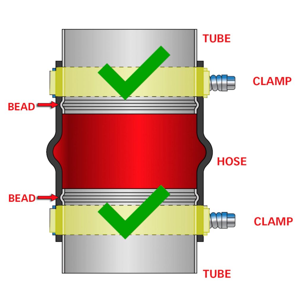
An improper installation, such as a clamp sitting directly on a bead or crossed diagonally, will result in a boost leak.
Intercooler Assembly Installation
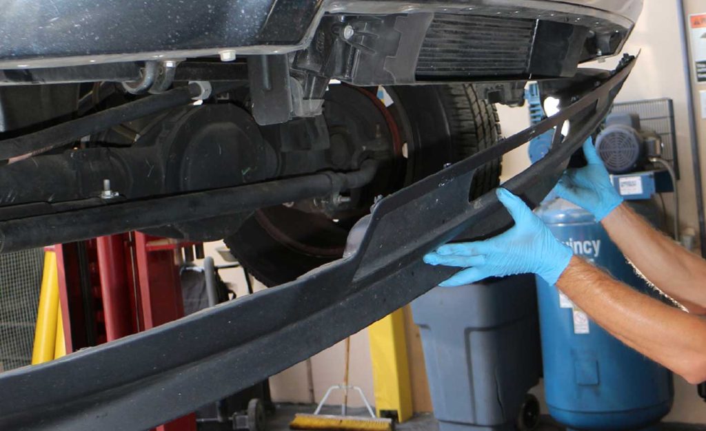
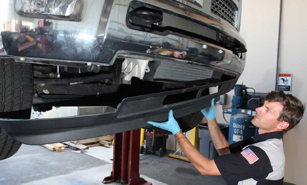
- On the 2013-up Ram 2500, 3500, 4500, and 5500 the Intercooler is located behind the front bumper, underneath the radiator. To begin, remove the front bumper air dam. This requires removing the two bolts and 15 retainer clips that attach the air dam to the bumper. These can be accessed from the back of the bumper. This requires a 10mm wrench or socket and a body clip removal tool.
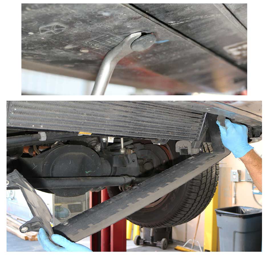
2. Remove the air intake shroud from the front of the intercooler. First, remove the two, lower, 10mm bolts, one on each side, that secure the intake shroud to the intercooler. Next, remove the three push pins that secure the shroud to the bottom of the intercooler. Remove the two upper 10mm bolts, one on each side. The intercooler shroud can now be dropped out the bottom. Set the shroud aside, it will be trimmed and reused when you install your new Banks Techni-Cooler.
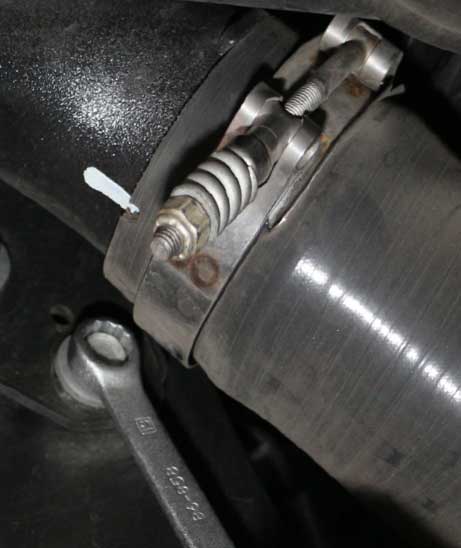
3. Before removing the OEM intercooler, first loosen the passenger and driver’s side boost tube clamps, using an 11mm wrench. Ensure that the boost tubes can freely be pulled off the intercooler inlet and outlet. Be sure to take note of the clamp orientation, as you will reinstall the new lower clamps with the same clamp positioning.
4. Loosen the four (two per side) intercooler mounting bolts. DO NOT remove them at this time.
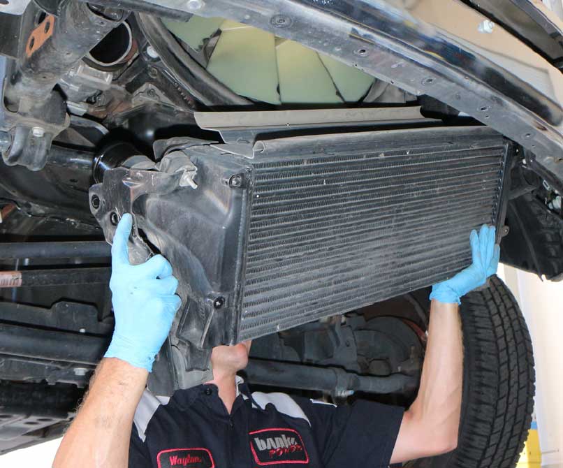
5. While supporting the factory intercooler, ensure that the left and right intercooler boost tube hoses are loose and will easily slip off. Then remove the four loosened mounting bolts and slide the intercooler down and out.
6. Loosen the upper clamp bolts on the right and left boost tubes and remove them from the vehicle. These will be replaced by the new clamps in your Banks Techni-Cooler kit.
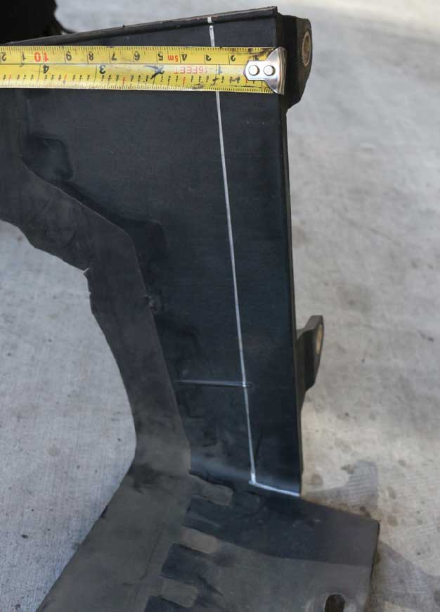
7. Due to the increased core thickness of the Banks Techni-Cooler, the OEM intercooler front air intake shroud will need to be trimmed. Mark the rear inside of the two side surfaces, 1-inch in from the back edge. A red or silver permanent marker works well for this task.
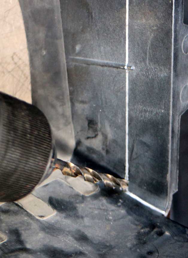
8. Where the marked line meets the sides on the front air intake shroud, drill a ¼-inch hole in the two corners. This will help prevent cracking of the front air intake shroud due to the stresses of road vibration. Cut the shroud along the marked lines, removing the portion of the shroud that was used to mount to the OEM intercooler.
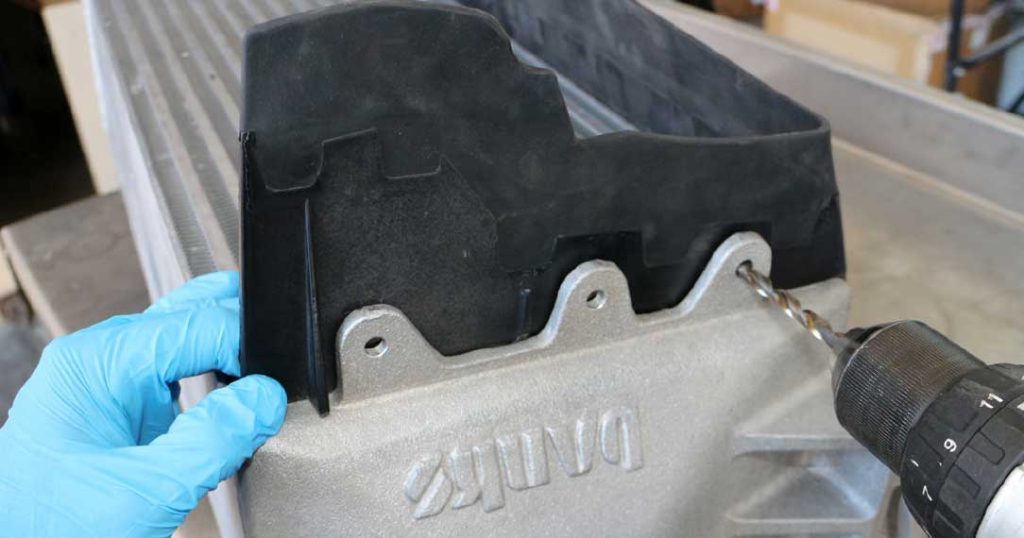
9. Place the front air intake shroud for the intercooler on your new Banks Techni-Cooler. Mark and drill the sides of the shroud using a 1/4-inch drill bit so you have three mounting holes on each side. Take care not to drill these holes too big, as the push pins that mount the shroud require a tight fit in the hole to be secure. Do not attach the front shroud to the intercooler at this time.
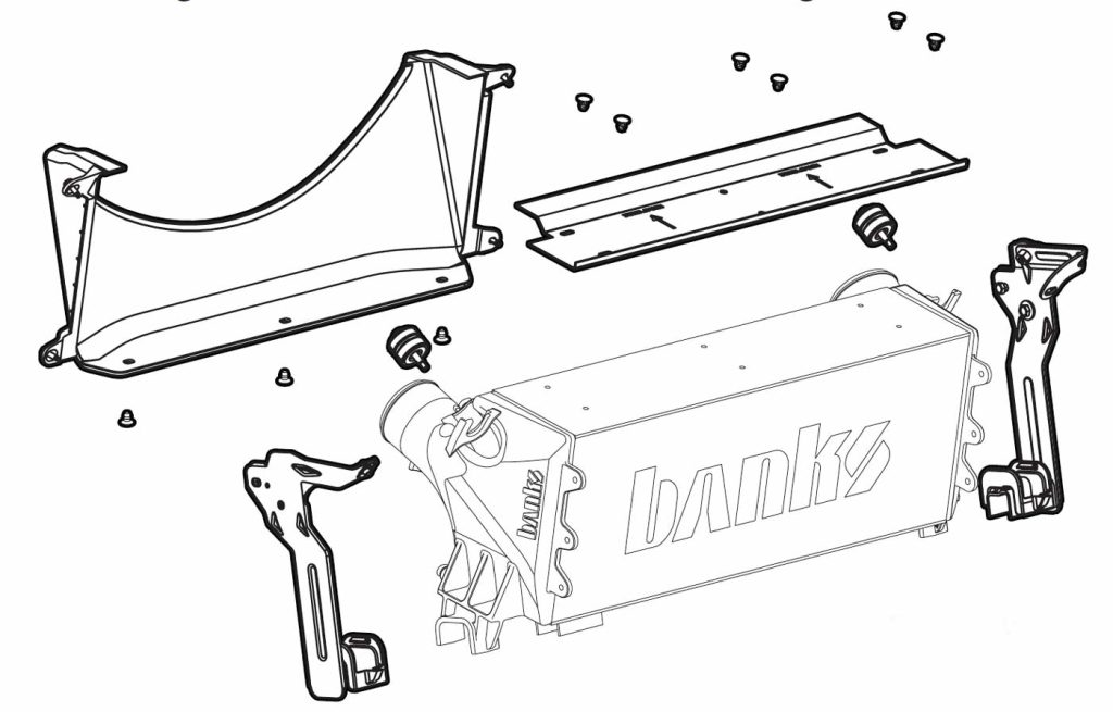
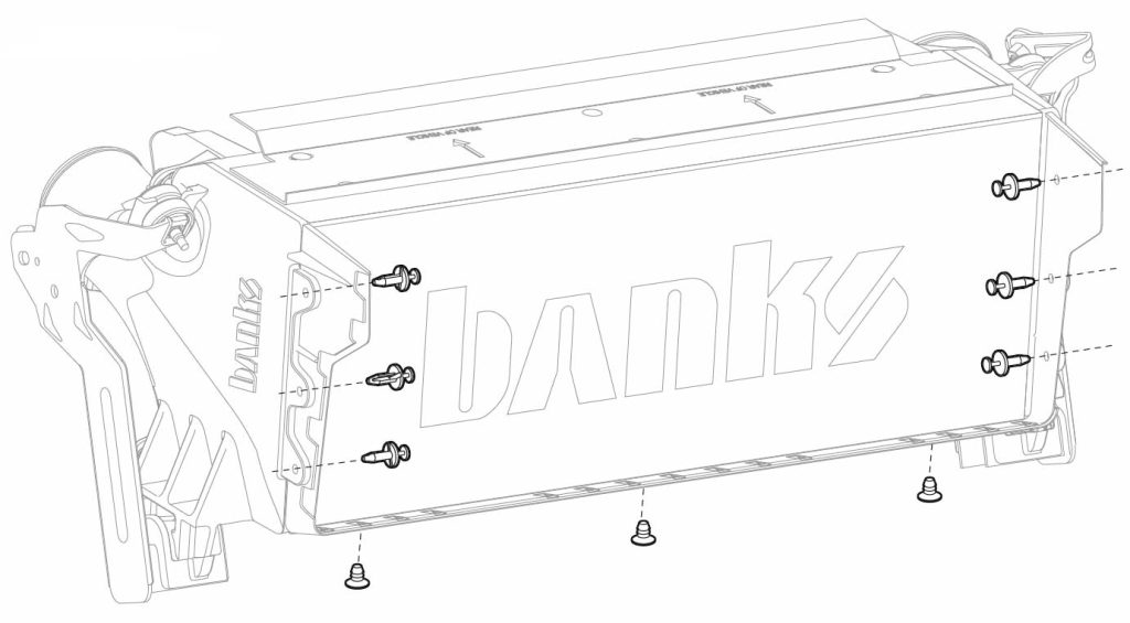
10. Transfer the left and right upper rubber grommets, lower rubber isolators, left and right mounting brackets, rear intercooler shroud, and plastic intercooler seal from your original intercooler to your new Banks Techni-Cooler. Replace the OEM plastic clips with the supplied ratchet fasteners to secure the rear intercooler shroud and plastic intercooler seal.

Removing the wheelhouse splash shields is not required but may ease the installation of the boost tubes. If the installation of the boost tubes is difficult, the wheelhouse splash shields can be removed to make the installation of the boost tubes easier.
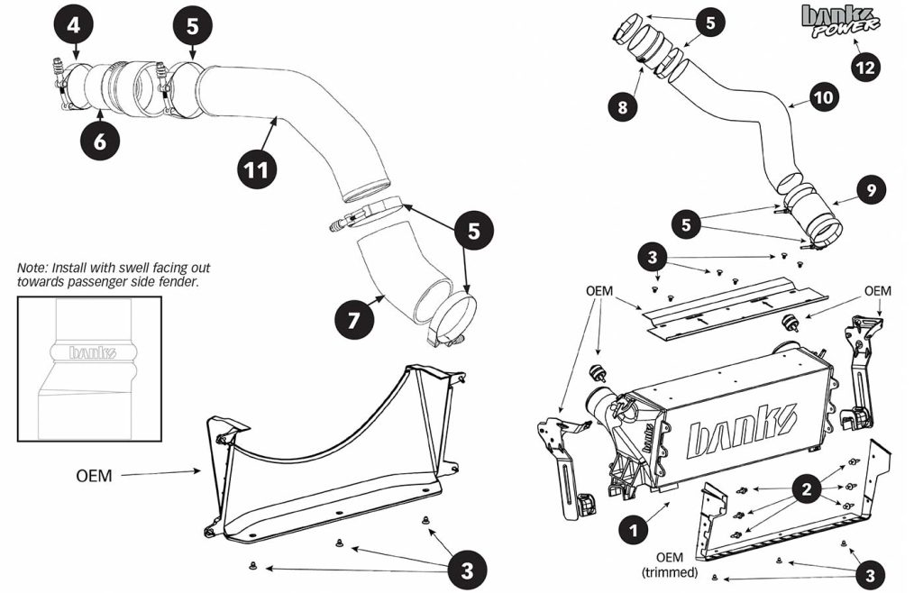
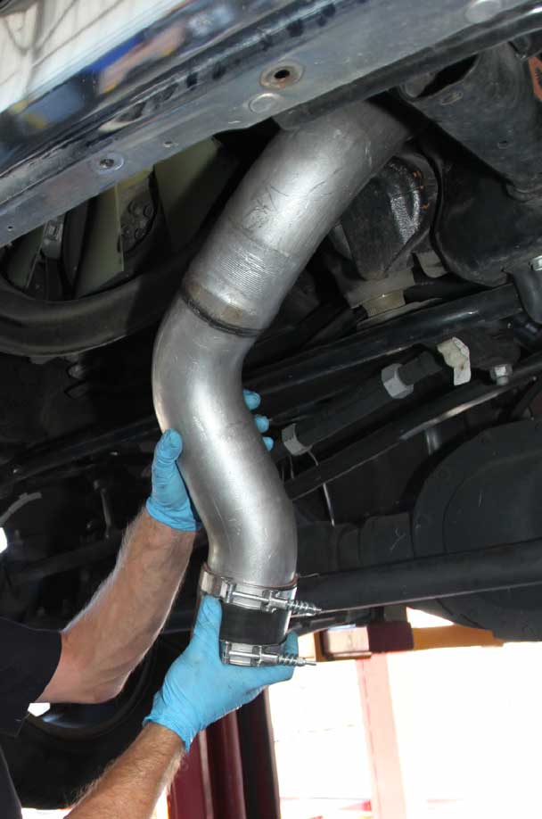
Assemble your new Banks boost tubes and clamp assemblies before installing them in the truck. These will be installed from underneath the vehicle. The boost tube connection at the intercooler end will be made from underneath the vehicle and the connections at the other end will be made under the hood. Note that using the orientation of the clamps listed below will greatly easy the installation process.
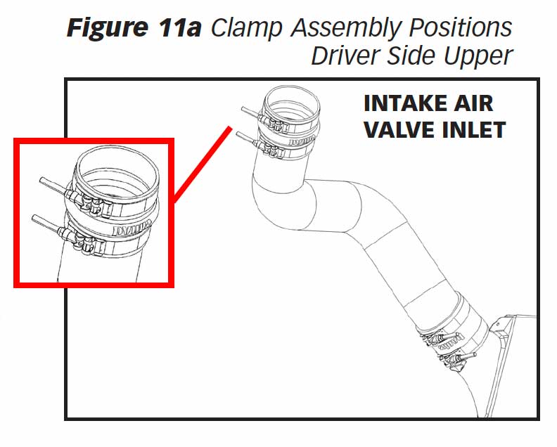
11a. Drivers Side Upper: Both clamps are on the firewall end of the tube, with the nut/bolt facing out to the fender.
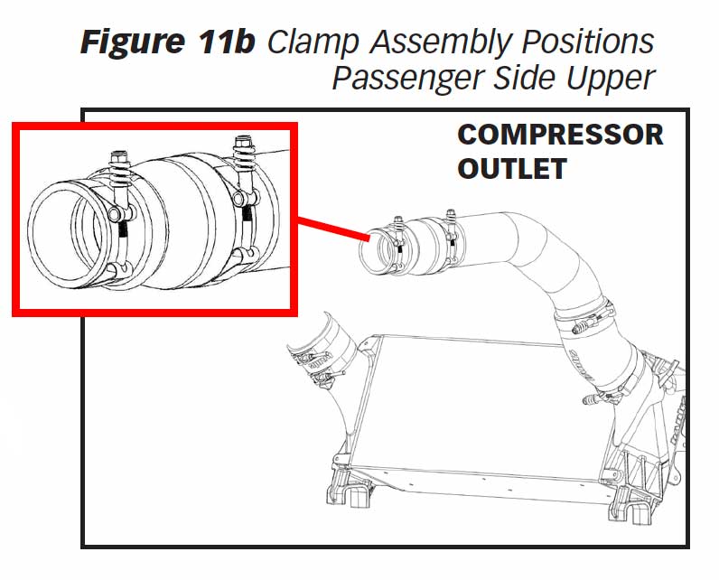
11b. Passenger Side Upper: Top/outer clamp is on the near side of the passenger wheel well, with the bolt facing up. Lower/inside clamp faces outward from the bottom of the tube.
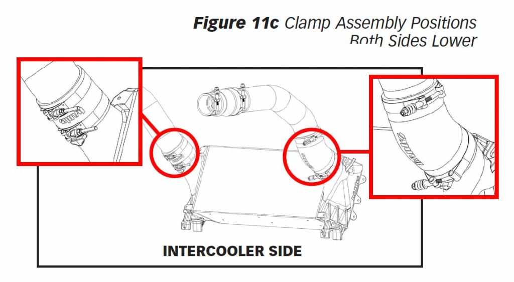
11c. Both Sides, Lowers: Both clamps are on the lower side, with the bolts facing inward.
12. Once your new boost tubes are pre assembled, they can be loosely installed in the truck.
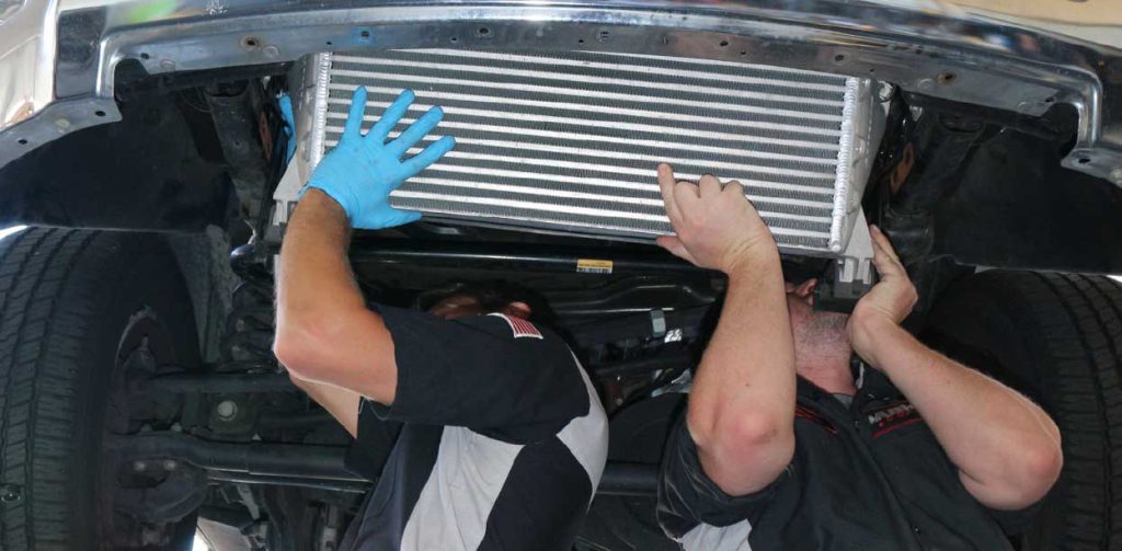
13. With the boost tubes in place, the new Banks Techni-Cooler can be installed. Support the intercooler and install the boost tube hoses over the Techni-Cooler inlet and outlet ports. Loosely install the four intercooler mounting bolts removed in steps 4&5. Do not tighten at this time.
14. With the Banks Techni-Cooler and boost tubes installed loosely, adjust the position of the intercooler in the vehicle to ensure that there is no contact with other components on the vehicle. The intercooler will rotate slightly around the four intercooler mounting bolts. Careful inspection should be made on the driver’s side around the intercooler outlet port to ensure the intercooler boost hose has adequate clearance to the radiator, along with clearance between the boost tube and frame rail. Once all clearances are verified and any necessary adjustments are made, tighten the four intercooler mounting bolts and the eight hose clamps retaining the boost tubes.
15. Install the trimmed front air intake shroud onto your Banks Techni-Cooler, using the six supplied push pins, and ratchet fasteners.
16. Reinstall the air dam on the front bumper.
17. Your system contains a CARB EO label for emissions purposes. This label should be placed on the grill/radiator cross member inside the engine compartment, so that it is easily seen by an emissions technician.
18. Go over all hose clamp connections and fasteners installed and ensure they are tight. Road test the truck ensuring there are no leaks. Be sure to recheck all the connections and retighten everything at least twice in the first three days or 100 miles.

19. Your system includes two (2) Banks Power decals designed to complement the Dodge Cummins Turbo Diesel emblem on your truck. Use the provided measurements to position the logos for a clean factory look.