Forced Induction Madness – The Birth of an Intake-Charge-Air Cooler
Here’s a video of the monster Steam Punk Banks Twin-Turbo Marine engine in action on the dyno.
By John Espino
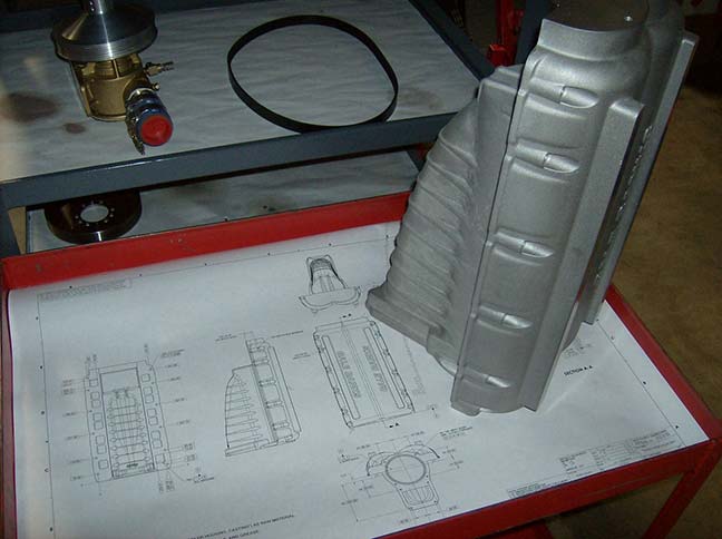
These past few Fridays we’ve been going through the development of what would become the Super-Twin Turbo (it has a longer name, but let’s not stress on that right now) to show a little of its origins, and that not everything you see starts out looking that way. Case in point is the intake manifold that houses the charge-air cooler. So this week we’re going to take a closer look at that.
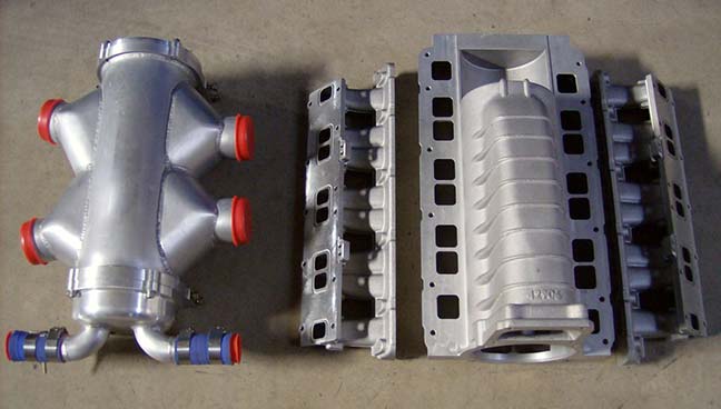
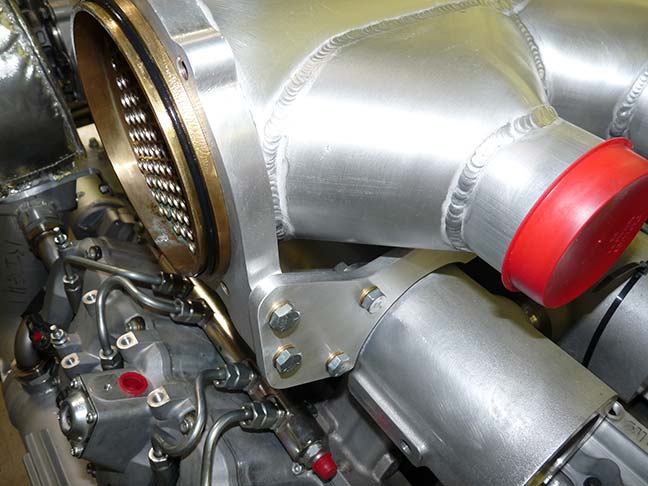
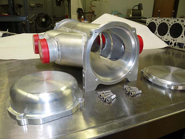
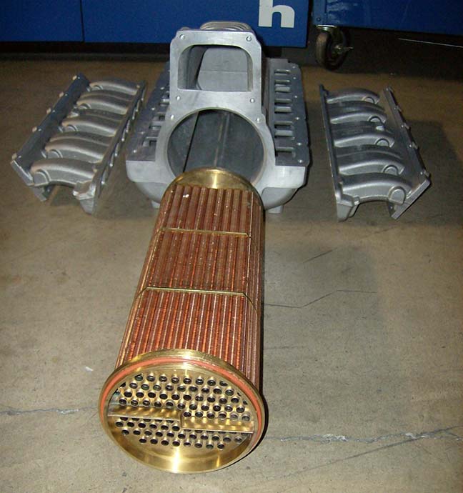
Being that this is a marine application there is plenty of cold water to draw from for the cooling of a liquid coupled charge-air cooling system, but you have to start with the proper components. Sea water is a pretty nasty thing: pour it on metal and it’ll corrode, drink it and you’ll go crazy. Most normal intercooler cores used in automobiles, even liquid-cooled systems, are made of aluminum… but aluminum wouldn’t stand a chance being constantly bathed in salt water. The intercooler needs to be made of a copper-nickel alloy to withstand the acidic torture. That covers the material used in its construction, but what about its very construction? For this application we chose a tube-and-fin configuration rather than a bar and plate. This is something you’d see more in the way of oil coolers and such, and our tests of this configuration have proven that it has the lowest restriction for the job and the best cooling. Our experience with this particular make up goes back to the Sidewinder Dakota Bonneville truck. In that particular application we used two smaller versions of this core in a close-looped ice water system to produce the same type of effect we’d get from a marine application (see more about the truck itself here). Of course there, the water in the tank was hot enough to make soup after each run. Here, we don’t have that problem because the boat is surrounded by a giant heat sync: the ocean. That two cooler core system used for the Salt Flat attack eventually became one larger core, the one we’re using here today.
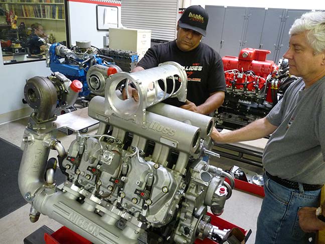
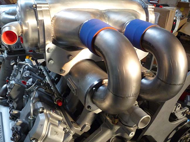
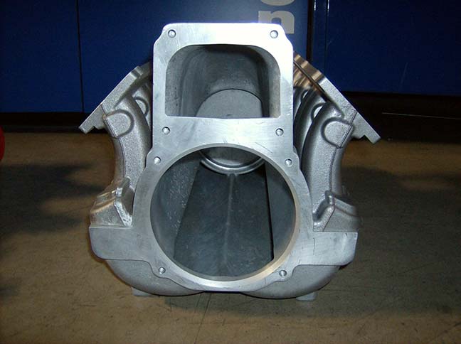
Since the final intake/cooler configuration would be made from the general design idea we had and the data we captured from the prototype we decided to start with the intake components we know worked: the core described above, and our Big Hoss Intake manifolds that we use in our racing efforts. The cooler casing was fabricated to house the core and get the compressed turbo air in and out with the least amount of restriction to the manifolds. The finished proto-part looks more like a steam generator than a cooler, but the results were great. From the data collected we actually changed the final design for the casting, and then further refined it thru CFD analysis. The final product is a high-flowing, compact design that incorporates its own intake runners. The cool thing (pun intended) about this configuration is that not only does it fit well in a boat’s engine compartment, but its design is also low profile enough to be used under the hood of a hot rod application. I’ll just leave that to your imagination.
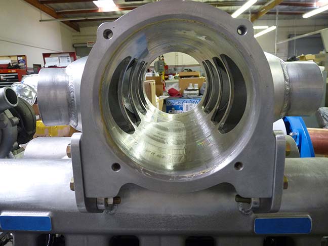
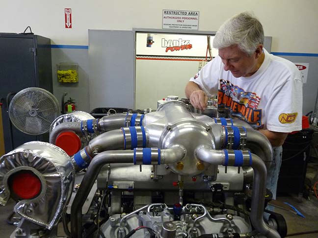
A couple of weeks ago I promised a video of the monster on the dyno in action. Without further ado we present the Steam Punk Banks Twin Turbo Marine engine (whew… that’s a mouthful!).

