

Project Blazer
Installation and test of Banks Sidewinder turbo for Chevy/GM 6.2L diesel trucks
It’s been said that there’s no good excuse for a naturally aspirated diesel in a light truck. While you can get away with it at sea level, the difference in power between a turbo and nonturbo diesel is like the difference between a V-6 and a big-block V-8. Not only can power outputs be increased with turbos, but emissions can be reduced. Gale Banks recognized this early on and has offered turbo kits for naturally aspirated diesels since the mid 1980s. The Banks Sidewinder kit was actually offered as a factory option in 1989–1991 GM trucks before the 6.5L V-8 Turbo was introduced. It made sense to go to Banks to solve our Blazer’s need for speed. A step-by-step installation follows, but a few general words are in order before we start.
The principle is simple. A naturally aspirated engine has to rely on atmospheric pressure, essentially the weight of the air over the earth (creating 14.7 psi at sea level), to fill the cylinders. At low rpm, there is enough time in the diesel intake stroke to fill the cylinder to as much as 85–88 percent of capacity. As engine speed increases, this percentage may drop below 80. The ratio of the theoretical amount of air the engine can inhale versus the actual amount is called volumetric efficiency. The fuel system is calibrated for this reduced, real-world amount of air so actual power output is less than the theoretical amount an engine of a given displacement could produce.
Forced induction puts the air in under pressure. In the case of our Sidewinder, that’s at up to 10 psi above atmospheric pressure. This can easily pack the cylinder to at least 100 percent of capacity. If you add the extra fuel needed for that amount of extra air, you are gaining power and torque and at least 100 percent volumetric efficiency.
The turbocharger is driven by exhaust gases from the engine via a high-temperature turbine wheel called the impeller. A shaft from the impeller is connected to another turbine wheel called the compressor. The faster the impeller turns, the faster the compressor turns, and the more pressure it makes. Both sides of the turbo are carefully sized according to engine displacement to produce the required amount of boost.
There are limits to the amount of boost an engine can tolerate, and Banks determined 10 psi is the safe limit for the essentially stock 6.2L GM diesel.
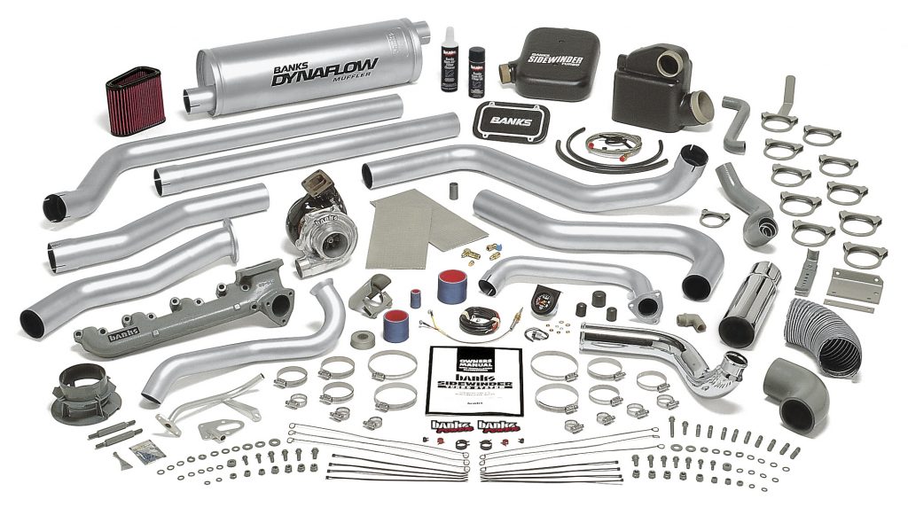
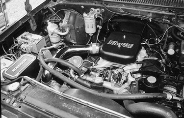
The Sidewinder kit consists of a large turbo with a new right exhaust manifold, an intake plenum, a free-flow air filter assembly, a free-flow exhaust system, a pyrometer, and a ton of smaller parts. This ham-fisted journalist was able to do the insto himself in about 18 hours. A vital part of the installation process is increasing the fuel rate. Banks gives you an arbitrary quarter turn of the fuel rate screw to start, followed by a double check on the road via the pyrometer (the exhaust temperature gauge included in the kit). We were looking for an EGT (exhaust gas temperature) increase to 1,100 degrees from a full-throttle, heavy-load run. Our first run was only about 950 and we needed to bump it up. Banks does not recommend EGTs any higher than 1,100 degrees for the 6.2L.
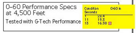
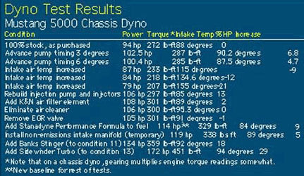
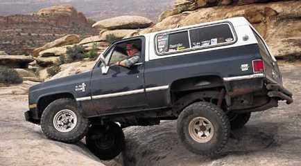
If you have followed the diesel buildup, you will recall that we had our power built by various mods up to 134 hp at the rear wheels, from 94 hp stock. At 4,500 feet, our 0–60 time was down to 16.4 seconds. Our Sidewinder boosted rear-wheel horsepower to 172 ponies (84 percent over stock, but bear in mind that 100–105 hp is a more realistic, well-running 6.2L rear-wheel power figure) and dropped our best 0–60 time to 14.4 seconds. That’s not bad for a 5,800-pound sled at 4,500 feet with 35-inch tires.
Since the Blazer is a nonwastegated turbo, you have to build some rpm before getting much boost. In our case, 1–5 psi was noted from idle to about 2,200 rpm, depending on load. Above that speed, it increased to 7–10 psi by the time we were past 2,500 rpm and stayed that way to our engine’s governed speed.
Freeway hill climbing is quite different. Our test hills are the “great equalizers” of the Rocky Mountains, Vail Pass (10,000-plus feet) and both sides of the Eisenhower Tunnel on Interstate 70 between Glenwood Springs and Denver. In both cases, where the truck previously had to grind up the steep parts of the slope in Second or Third at 40–50 mph, the turbo allowed the unit to maintain 65 mph in Fourth (OD) gear half the way and hold the same speed in Third gear on the steeper parts at the tops of the passes.
We cannot report on fuel mileage, because we added the Off-Road Design Doubler at nearly the same time and, as expected, the drag of those extra gears have cost us some mileage. Under normal circumstances, the mileage would theoretically increase slightly because less throttle is required to do the same work. Trail/low-rpm performance is unchanged (there’s next to no boost at 1,000 rpm), though we look forward to seeing how the extra power will help in situations where higher-rpm horsepower is needed, such as on certain types of mud and sand. This is where our diesel really lacked.
So ends Project Blazer. Actually, these buildups never really end. True gearheads are never able to complete a project, because some new goodie is always appearing on the horizon. We had a lot of positive feedback on this buildup and we’d like to thank the readers who took the time to write in with comments and questions, or just to tear out our livers! We’d also like to thank the many fine companies that supplied parts and information to turn our old Blazer into the gnarly beast that it is. The diesel Blazer will remain a testbed for new ideas, so you can still look forward to seeing it showing up in the pages of Four Wheeler from time to time.
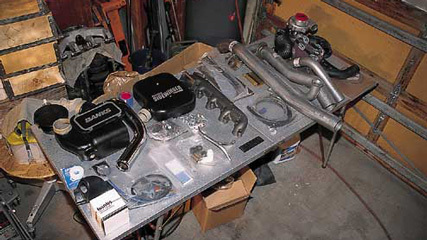
Step one is to lay out the kit and check off all the parts from the parts list on the instructions. It’s a sizable list and pile of parts. Our list was a bit shorter than normal because we had previously installed the Banks exhaust system. Only the front part of the exhaust system was changed.
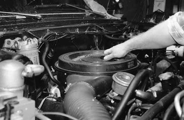
The teardown starts by disconnecting the batteries. Next, remove the air cleaner, air cleaner brackets, and silencer (ours had been removed during the previous Stinger installation).
We had previously installed a nonemissions intake manifold, which is without the EGR valve. We essentially reverted to a HD emissions engine, which is legal outside California. If you live in an emissions-controlled area, Banks will send a light-duty emissions kit. Don’t worry, the EGR and other parts are virtually no cost to power with the turbo kit. Intake restriction becomes a moot point with forced induction.
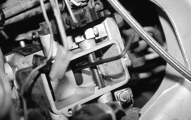
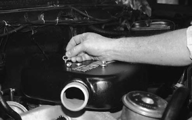
After cleaning up the area around the injection pump and the pump itself, you get to adjust the fuel rate. We turned the adjustment screw a quarter-turn clockwise with the 5/32-inch Allen wrench. The adjustment screw turns tight, so make sure you use a new Allen wrench. If you strip the screw, you have to remove the pump and take it to a diesel shop for repair.
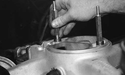
After you’ve removed the original air cleaner studs, install the new pressure chamber studs with the two 5/16-inch washers between the stud and manifold. We used red Loctite on these to prevent them from backing out.
The plenum can be installed after the new round gasket is installed on the intake manifold. Special rubber sealing washers are installed over the protruding studs and the self-locking nuts can be installed. A tapped hole is drilled into the plenum for a boost gauge fitting. Be sure to install the fitting or the plug provided in the kit.
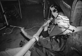
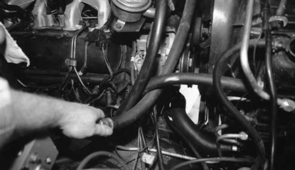
The fun part: removing the exhaust. Fortunately, all we had to remove was the Banks Stinger front Y-pipe assembly. You’ll need to save (or buy) one exhaust donut and one exhaust flange from the old stuff for re-use with the new crossover pipe.
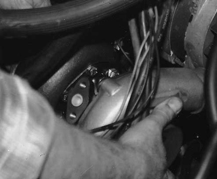
The next step is to remove the fuel lift pump from the engine and install the new spacer plate that has a drain fitting for the turbo lube oil. The pump pushrod will slip down, and you will need to grease it in the up position to install the pump.
Remove the four glow plugs on the right bank and put the wires up out of the way. The right exhaust manifold comes off next. Clean all the carbon off the head mounting surface. Drain the coolant and replace the existing lower radiator hose with the new one from the kit. There is a ground wire point nearby. If the ground wire bolt chafes the hose, relocate the ground cable.
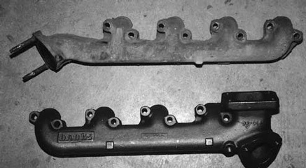
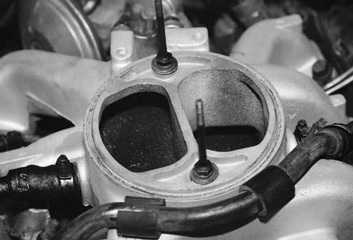
After you install the pyrometer fitting into the new exhaust manifold, you can install it. Snaking in the manifold involves keeping several of the bolts in place as you install it. No exhaust gasket is used, but a light coating of grease on the mounting surfaces will carbonize and seal some imperfections. We used some card paper on the bolts to hold them in place. The paper was then pulled off after the bolt was started in the head. Note also that antiseize was used on the bolts. Note the differences between the original manifold (top) and the new Banks piece (bottom).
The turbo can be temporarily installed after you loosen the bolts that connect the impeller (hot) side to the center bearing housing, as well as the six that secure the compressor housing. Rotate the impeller housing as required. When this position is found, tighten one bolt and do the same thing on the compressor side using the chrome plate boost tube as a guide. Remove the turbo, resecure all the turbine housing bolts, and permanently install the turbo using the stainless steel nuts and washers provided.
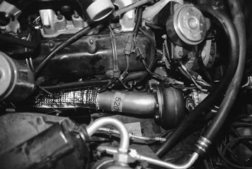
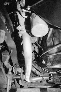
The turbo downpipe can be installed with the heat shielding. The pipe will interfere with one upper shock mount on quad-shock trucks, so the pipe must be dimpled to clear. Adjust the shielding to protect the nearby injectors, return hoses, and glow plug wiring. Adjust the positioning of the hoses and wiring to provide maximum heat protection. You will also have to adjust the AC lines carefully to clear the turbo.
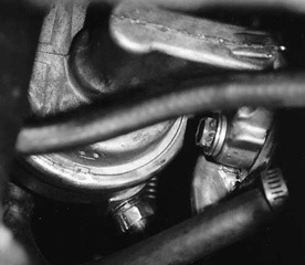
The new crossover pipe from the original left exhaust manifold to the new turbo manifold can be installed. The turbo side of this new pipe has a welded-on flange, but on the other, you will reuse the original donut and flange. Install the heat shield on the pipe where it runs near the fuel pump on the right side. Most likely, you will need to reroute fuel lines at the pump for maximum clearance from the new pipe. Note that the new crossover is tucked up nicely and does not hang low as the Stinger crossover did.
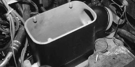
The cast air filter housing can be installed by removing the right battery and mounting the bracketry. A formed elbow connects the turbo compressor inlet with the air cleaner housing. A short piece of hose also connects the housing inlet to a plastic air inlet that protrudes through the radiator support. The hole is prepunched in most trucks. The reusable oiled cotton-gauze free-flow filter can be installed, and the air filter top can be bolted in place. A breather hose also connects the CDR valve with the air filter.
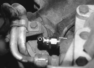
Remove the 1/4-inch NPT pipe plug from the oil gallery above the oil filter, near the oil cooler lines, and install the adapter and the 90-degree elbow. The braided oil feed line can then be routed up to connect with the fitting on top of the turbo. Before you connect the line at the turbo, pump in a few squirts of motor oil to prelube the turbo before startup. Take care to prevent the braided-steel line from chafing against fuel lines.
Now is the time to install the exhaust system, pyrometer, and optional boost gauge. The Banks exhaust is different according to application, but easy to figure out. In the end, we were forced to have a new exhaust system fabricated because of space considerations with the Off-Road Design Doubler that was installed at nearly the same time. After double-checking everything, you can start the engine and check for leaks. Then, the payoff test drive. Yeeehaaa!