Jay to Gale: Hey, Can You Banks This? Part Four in a Series. Follow along with us as we take a behind-the-scenes trip through the Banks Advanced Prototype Engineering laboratory to view the magical transformation of a Cold War-era giant into a modern superpower.
Part Four in a Series: 1 | 2 | 3 | 4 | 5 | 6 | 7 | 8
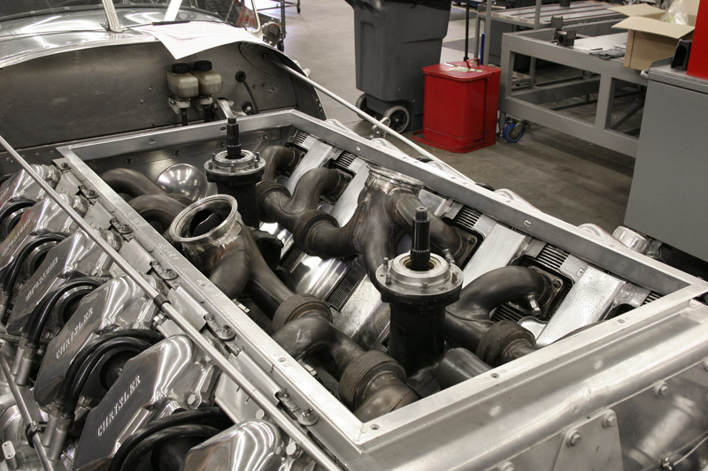
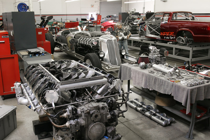
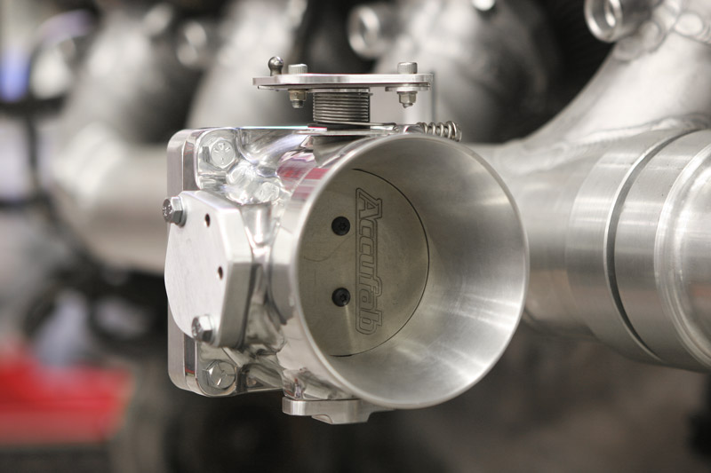
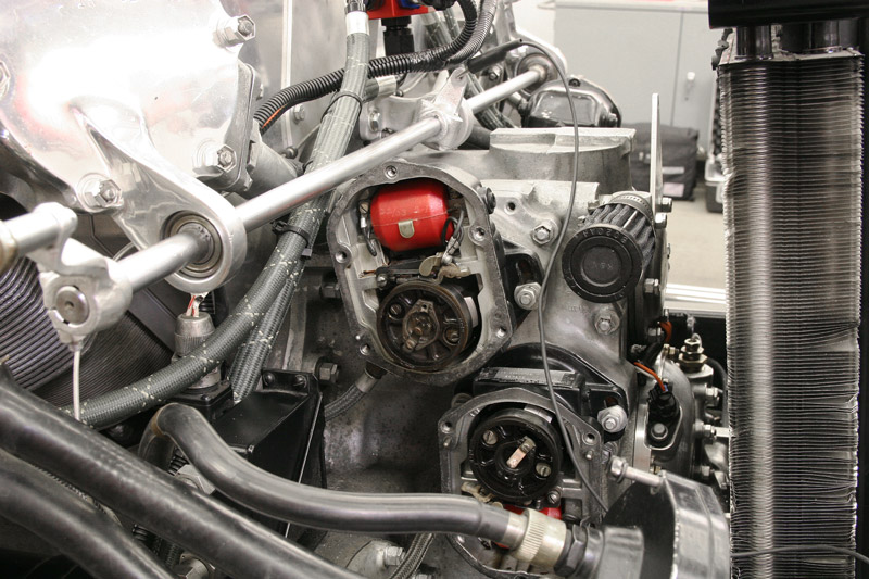
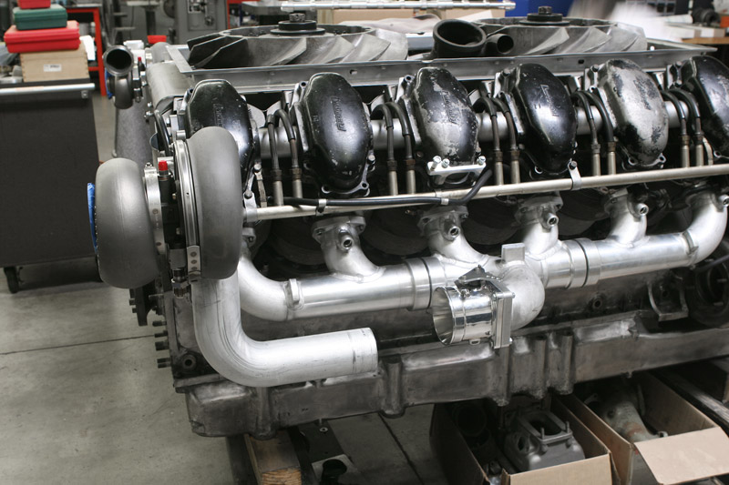
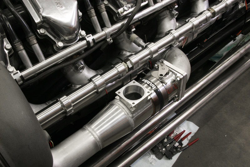
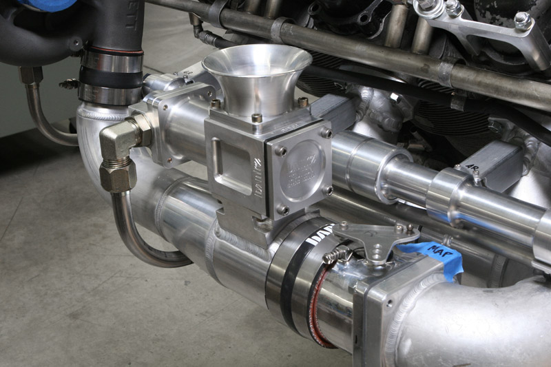
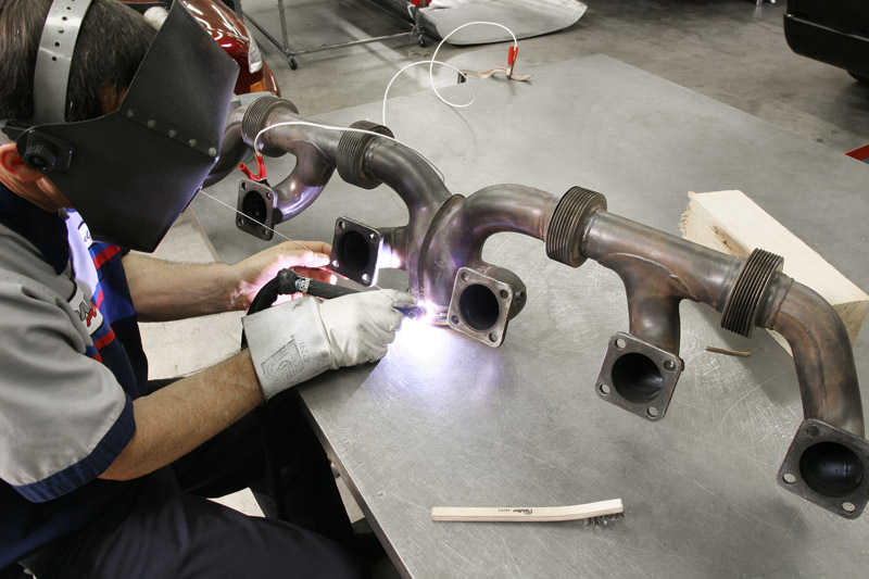
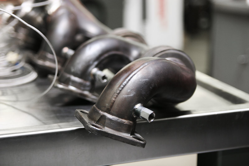
Banks Race Shop with our mock up M-47 Patton Tank Engine in the foreground. The 4 magnetos, 2 per bank are visible on the front gear case. Jays Tank Car is in the background, our diesel pro stock truck project is on the chassis jig to the right and the wing of our diesel dragster is visible over the rollaway tool boxes.One of Gale’s goals when converting Jay’s engine to electronic fuel injection was to improve driveability and throttle response. These twin 75mm throttle bodies, designed for Ford Mustang applications, replace the original Stromberg 2bbl. carburetors. We could have gone bigger, but this was a good compromise for off-idle transition. We’ve modified them with new throttle levers and covers over the idle bypass ports. A single throttle position sensor mounts on the right side throttle.The AV 1790 V12 has a long rotating shaft across the front of the engine to link the carburetor throttles together. We’ll fabricate new throttle pull-rods to utilize the original cross-shaft. In this photo the two right bank magneto covers (there are four magnetos) have been removed. Although we could have converted the engine to electronic ignition, Gale wanted to retain the magnetos to maintain the period look.With the manifolds, throttles and turbos in place, we can begin to mock up the boost tubes that connect the turbo compressors to the engine. Here the right boost tube has yet to be trimmed to align with the throttle body. It sure is convenient to have both the Tank Car and a mock-up engine available for fitting parts.Like the intake manifolds, the boost tubes are a fabricated combination of machined transitions and elbow bends. The shuttle valve will mount atop the 4-bolt flange next to the throttle body inlet.The finished boost tube with shuttle valve mounted. The 3/4-inch manifold pressure reference tube is connected to the fitting on the end of the shuttle valve. A short section of 4-inch diameter silicone hose joins the boost tube to the throttle body. The discharge horn on top of the shuttle valve was later changed to a side-exit design to prevent road debris from sticking the valve open.Now that we’ve finished the intake side of the turbo system, we can turn our attention to the exhaust. The AV 1790 engines had a beautifully streamlined pair of center-outlet stainless exhaust manifolds nested in the engine valley. Later versions like these even had expansion bellows flex-joints between adjacent cylinders. Because the flow dynamics looked so good, we decided to retain these manifolds.One source of trouble on the AV 1790 exhaust manifolds was leakage at the outlet flanges. With the higher exhaust pressure and temperature associated with turbocharging, we couldn’t afford any leaks. We solved this by removing the original flat flanges and welding on a set of 4-inch stainless v-band step-flanges that we made for our Sidewinder Duramax road-race truck.While the manifolds were off the engine, we added fittings for exhaust temperature probes to aid in tuning. Look at the exquisite design of the original flanges and elbow sections. Those elbows are two-piece clamshell stampings, seam-welded together!For episode 5, click here