Designs and Designers
With large numbers of new Banks Power products coming on line annually and a like number of very short-run specialized components needed for the BankSpeed racing program, there’s always a flood if new items on the “drawing board” here in Azusa.
At Banks, new parts are being conceived and designed on a daily basis.
With large numbers of new Banks Power products coming on line annually and a like number of very short-run specialized components needed for the BankSpeed racing program, there’s always a flood if new items on the “drawing board” here in Azusa.
Sharp-eyed readers will take note here that the word drawing board is rendered with quote marks in the above paragraph – – that’s for a good reason. We still have one in operation here at Banks Engineering. A drawing board that is.

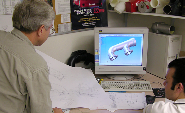
Interestingly enough, it shares office space with three ultra-high-powered PC’s with BIG screen monitors, each running the very latest 3D-CAD software and operated by a couple of young-looking engineers who know every X, Y, and Z axis in the multibody, hybrid solid, and parametric surface modeling world of “Solid Works.” (And, if you think that I know what all that means …)

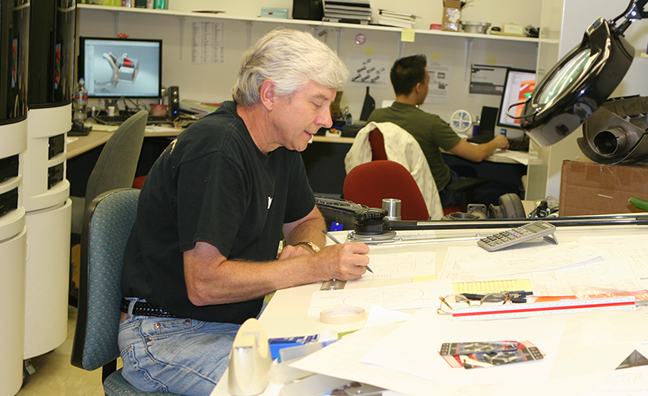
The lone drafting table in the room looks exactly like one of the hundreds that you’d see in those WWII shots of aircraft companies were everyone in a huge, well-lighted drafting room is wearing a long-sleeve white shirt and dark tie.
Those draftspeople spend 8 hours a day with a pencil clutched in one hand, an eraser bag in the other, and their other on the center knob of the drafting machine, moving it scant millimeters at a time, hand-drawing (with the help of a lot of mechanical devices) the blueprints for the latest left-side/right front widget holder flange. Hold it, hold it … That’s three hands listed above. OK, so that was to prove a point that the use of a drafting table is a vanishing (like three-armed people) thing, art, skill, avocation, way of life.
The guy who sits at the above-described table and actually puts (mechanical) pencil to velum is Bob Robe. Robe is Banks’ chief mechanical designer and has (quite literally) been with the company longer (31 years) than either of the other two designers in the room have been alive.
An accomplished freehand artist in his own right, Robe respects what the guys with the mouse pad and the big screen monitors can do with a little stream of 1’s and 0’s, but, like readers who still prefer turning pages and using bookmarks, he likes the feel of pencil-to-paper more than finger-to-keyboard for his technical drawings.
And that’s actually good because Robe can quickly sketch out an idea, maybe even make a cardboard cut-out of a bracket almost while the CAD system is still warming up. Equipped with a battery powered headlamp, I suppose that Robe could continue right on drawing during a power outage, where the designers might be throwing their hands up and trying to remember when they did their last global save. (Of course all data on all computers at Banks is backed up continually and all if them have individual backup power units … which sort of blows my clever little comparo.)
But then there’s all the highly-complicated curved aerodynamic shapes that Banks builds – – those are just the perfect place for the CAD-ware to do its thing. Especially when one needs to see (Ok, “visualize”) a part in 3D space. It’s well known that most people are not all that good at imagining what a final product will look like even from the best 2D engineering drawings.

Almost being able to reach out and touch the finished object on screen is more than a plus in those situations. When fully modeled and given a “surface”, the on-screen view looks deceptively like a professional studio camera shot of the finished product and that works quite nicely.
The same applies to project managers who must sign off on each stage of a project’s progress and who need the very most accurate renditions of how the finished part or product will appear. Needless to say CAD images are critical parts of the process in any manufacturing situation these days.
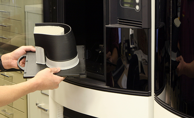
There’s one more step in the “visualization” process that’s used at Banks and that’s the rapid prototyping machines. These cool (no pun intended) refrigerator-sized devices get sent a 3D file of a new part from the designer’s computer and simply proceed to make an exact, full-scale prototype out of melted ABS plastic, layer by layer. Each layer is extruded only ten-thousands of an inch thick at a time until the part seems to magically “grow” in build chamber right before one’s eyes. The results come out of the machine hot to the touch, full-size and, in the case of items like air intakes and scoops, usable to instantly verify performance parameters on the flow bench and even right under the hood of a test vehicle.

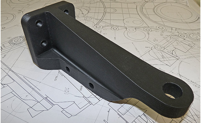
Some of the larger pieces are made in multiple sections which are subsequently fused together to form a hands-on engineering version of a new design which is then used to judge appearance and style as well as check size, fit, and clearance in the vehicle. In the case of something like a custom engine mount which is intended to be made in steel, the ersatz part can’t be used to take a load, but, using it instead of a guess, the engineers and mechanics know that the final part will fit perfectly where it was designed to fit.
The take away from the above is that Banks uses what works best where it works best and that education and experience are an extremely strong combination especially when given the right “tools.”

