
Gale Banks Engineering’s Banks Brake and Transmission SmartLock
Power Stroke Registry Fall 2002
Gale Banks Engineering’s Banks Brake and Transmission SmartLock
The reasons to add some additional braking power to your Power Stroke have been well documented in past issues of the PSR Magazine. With no throttle-valve restriction in the intake system as on a gasoline-powered truck, a Diesel engine is a free-flowing (air) pump that lets air out almost as quickly as it enters. There is very little restriction. The butterfly valve on gas rigs gives them so called “compression braking” which is not available on a Diesel engine that is not equipped with some type of engine brake. Compounding this issue is the popularity of automatic transmissions in light-duty trucks; it is a recipe for lots of Go-Power but very little Whoa-Power.
Mr. Gale Banks has been in the business of making things go fast for decades, and now Gale Banks Engineering is applying their talents to slowing those fast-moving loads as well.
Because Banks has been focused on going fast, efficiently for so long, their focus when making their exhaust brake was not only to make a brake that worked well, but to insure that their brake did not inhibit performance when it was not being used. Banks Engineering notes that the factory warm-up valve restricts the turbulent flow of air as it leaves the engine because of its location just after the turbine wheel. Banks argues that even with a high-performance exhaust the standard outlet and backpressure valve restrict exhaust flow enough to reduce performance.
The Banks solution to this was to locate the exhaust butterfly valve further away from the turbine outlet and to increase the size and length of their brake casting. Where the Banks Brake mounts to the turbine the casting is larger and shaped to increase flow, as is the remainder of the casting leading to the butterfly valve (braking valve) and their new outlet pipe. When it’s time for stopping, Banks says that their brake produces consistently higher braking output compared to competitive exhaust brakes.
The SmartLock
Many times in the PSR, I have preached how important it is to have something to strengthen or lock-up your torque converter on your automatic-transmission-equipped Power Stroke. The same issues of overheating because of heavy loads when you are powering your load up a grade are the same problems you can experience when using a non-locked-up automatic transmission to slow your load. The slippage of the torque converter and what that slippage does to automatic transmission fluid (heat) can cost you many thousands of dollars because of a ‘cooked’ transmission. And, a transmission that is not firmly connected to the engine will not allow the backpressure generated inside the engine to be transmitted to the rear wheels to slow the truck. The Banks SmartLock is designed to cure or significantly reduce these problems.
The Banks SmartLock is essentially a plug and wire-in module that increases your transmission’s line-pressure and locks your torque converter at engine speeds above 1600-rpm in any gear. This greatly improves the transmission’s holding ability while braking and prevents excess transmission slippage. Locking the torque converter reduces transmission-fluid temperatures, and this can greatly increase the life of your transmission.
The Installation – Phase One
Installing a typical exhaust brake that replaces the stock warm-up valve is by no means a task for a beginner do-it-yourself-er, but it is not necessarily a job that requires expert skill either. I would consider myself a home mechanic of intermediate skill. The owner of the truck we were using for this installation, Modesto (Mo) Reyes, is of similar skill. I would also suggest that you allow two full days to complete the installation of the Banks Brake and the Banks SmartLock transmission controller. That is about how long it took us. While you can install the SmartLock without installing a Banks Brake, if you install a Banks Brake (or other exhaust brake) you need to add something to tighten-up your automatic transmission to prevent overheating and other performance failures.
Although I had removed and replaced the old turbocharger on old Project Pull Dog years ago, I had never dug under the cowling of a 1999-up Super Duty to work on one of these harder to reach turbochargers. Mo and I had planned to start at 10:00 AM on a Saturday morning, but didn’t really get started until 11:40 AM. We were not concerned, as it was mid Summer (July) when the days were long. Modesto is a car nut, and at least equally enthralled with his automotive obsession as am I. He worked a ‘graveyard’ shift the night before but was raring to install the Banks Brake on his 2000 Limited Edition F-350 dually. His truck has many neat features, but those details will have to follow in a future feature article.
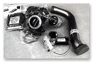
In addition to having a bit of mechanical skill and experience before you tackle an installation like this, it is helpful to have some knowledge of the Power Stroke Diesel engine. For example, the Banks Brake instructions tell you to move the ‘MAP’ sensor out of the way but there is no picture of this part. Mo and I both have a little familiarity with the Power Stroke Diesel, and the instructions didn’t cause us any confusion. Due to time constraints, neither Modesto nor I had looked at the instructions, or even opened the Banks Brake shipping box before we started our installation. This is a testament to the clarity of the Bank’s instructions and completeness of the kit. We opened the box, removed the parts for a “before” photo of the pieces and started reading the instructions and performing the tasks one step at a time.
WARNING! NEVER WORK UNDER ANY VEHICLE SUPPORTED ONLY BY A JACK. USE PROPER JACK STANDS AND WHEEL CHOCKS TO SUPPORT AND STABILIZE YOUR RIG.
Step 1 Remove both of the battery grounds.
Step 2 On the passenger side of the truck remove the MAP sensor from its mounting location and move it to the side so it is out of the way to allow access to the turbocharger.
Step 3 Remove the passenger and driver’s side boost tubes (intercooler tubes) and the intake plenum form the engine to allow access to the turbocharger.
Step 4 Locate the 2-bolt flange on the forward end of the intermediate pipe (down pipe) or the catalytic converter inlet under the truck. Measure 24.5-inches forward/up the stock pipe from this location and make a mark on the pipe at its centerline as shown in the instructions.
This is because in the following step (#5) you will cut the stock down pipe at your mark to allow fitment of the supplied Banks pipe which is required due to the design of the Banks Brake housing, which is longer than the stock backpressure valve.
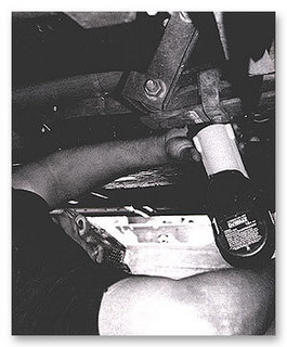
Step 5 Use a reciprocating saw or hacksaw to cut straight through the stock pipe (and heat shield if so equipped) at your measured mark. Loosen the V-band clamp at the outlet of the turbocharger and remove the upper portion of the (cut) turbine outlet pipe. Save the V-band clamp for reuse.
The above step 5 is simple enough though this is where we ran into our first snag. The cutting of the stock downpipe was not a problem with Modesto’s cordless reciprocating saw. He was smartly wearing goggles but was getting peppered with hot pieces of falling metal. Modesto emerged from under the truck with the statement “long sleeves are recommended”. Having extra saw blades is also a good idea; Mo bent his first blade after he recoiled because of the hot metal falling on him.
The snag came with the very simple task of loosening and then removing the V-band clamp that secures the turbine-outlet pipe to the stock backpressure valve. We loosened the clamp without a hassle, but the V-band clamp was apparently rusted to the turbocharger on this two-year old truck. We gently pushed, tapped, and banged on this clamp for over an hour. We were afraid to use too much force and damage the clamp, as we knew we needed to reuse it. Finally I started hitting the V-band clamp a bit more firmly with the small sledge hammer we had available, and it broke the rusty clamp loose. This was a simple task, but we encountered “real world” delays. This is why we recommend you give yourself a weekend to do this installation, and you will definitely need a second pair of hands, too.
Step 6 Remove the factory heat shield from the upper portion of the turbine-outlet pipe, cutting through the straps holding on the heat shield. I suggested that Mo try cutting in the center of the weld holding the straps in place at an angle. After doing so Mo was easily able to pry-up each band securing the heat shield.
Step 7 There are two different heat shield configurations that are both covered in the Banks instructions. Modesto’s truck utilizes the long L-shaped heat shield which we cut through during the removal of the stock pipe. We measured and fit the heat shield on the new Banks turbine outlet pipe, insuring the end of the shield clears the expanded end of the Banks pipe. We then used the two supplied number-48 worm-drive clamps to attach the shield.
Step 8 Disengage the stock exhaust-backpressure-control rod after sliding the clip on the end of the rod toward the turbo/driver’s side. This rod is at the bottom of the turbine housing, not the rod on the top of the turbo which is the wastegate actuator.
We struggled with this clip for a few minutes, not really knowing if it was to be slid down or away or how much. We ended up pushing down on the clip more than pushing it toward the driver’s side (one of our barbarian performances of the days) until we finally realized that the clip needed to be moved horizontally an inch or more to allow us to release the mentioned rod.
Step 9 Using a pry bar, or similar tool, bend the mounting bracket of the (automatic) transmission dipstick tube to allow clearance for the brake housing. The dipstick tube should move about one inch at the bracket and about six inches at the top.
Modesto has purposely bent many transmission tubes for clearance on automotive projects, and he chose to insert a screwdriver into the transmission tube’s opening/top and bend the tube over toward the driver’s side.
Step 10 Locate the engine-lifting hook at the rear of the block on the passenger side (near the valve cover) and remove it. This allows clearance for the installation of the Banks Brake, and Mo and I had removed it earlier as we had read forward and the hook was in our way. It is not necessary to re-install the hook.
Step 11 Remove the stock exhaust-backpressure-control valve assembly from the factory turbine housing by removing the seven, 12-point 8mm bolts. Retain these bolts for reuse. This was our second snag.
Modesto has a fair complement of tools, but a 12-point 8mm socket he has not. Pull Dog is well equipped as you know, but our Craftsman tool set behind our back seat is a cheaper 6-point kit. After eating some delicious homemade and traditional tacos prepared by Lillia Reyes, Mo and I needed to make the ten-mile trip into town from the suburbs in search of the right tool.
After a brief Starbuck’s stop to fill-up on some liquid energy, we stopped at my house and confirmed I only have a 6-point 8mm socket in my top-box. But we loaded my tool box into the back of Pull Dog as a back-up and to supplement Modesto’s slightly disorganized assortment. Included in this tool grab was my 26-piece Craftsman metric combination wrench set, which includes an 8mm, 12-point wrench.
We stopped at Home Depot and then at Lowes in an attempt to find the 12-point socket we needed, and to avoid driving across town to Sears to buy the proper socket. At Lowes, Mo found and purchased a 12-point 8mm socket, but it was a deep set socket, and I feared it would be too long for many of the tight spots where we were going to need the tool. We ran one more errand and hurried home to get back to work. Our total trip time was about two hours, which we later subtracted from out total installation time.
Of the seven 12-point bolts that we needed to remove before taking off the backpressure valve, the one in the ten-o’clock position, when looking at the turbo from the passenger side of the truck, gave us the most difficulty. There was simply no room to use the 8mm deep socket behind the turbocharger, even with a swivel socket and extension attached to our ratchet.
We finally resorted to using the 12-point box-end wrench I had brought as a back-up. With my long arms I was able to reach behind the turbo and turn this very hard to reach bolt a fraction of a turn at a time, after struggling to put the wrench on the bolt by feel for each small turn. After the bolt was loose, I was able to turn it with my fingers and run it the rest of the way out. After much delay, because of the V-band clamp and the very difficult access to the bolts to the rear of the turbocharger, we had the stock backpressure valve removed.
Before continuing we decided to weigh the stock backpressure valves and the new Banks Brake. I have written before how aftermarket parts and accessories add weight. The stock backpressure valve weighs 5-pounds, and the new Banks Brake weighs 15-pounds, a 300% increase. This is not to say the Banks Brake is not worth the added weight, on the contrary most Power Strokes Diesels can shrug-off extra pounds. The increased braking performance is worth every ounce of added weight.
Step 12 Slide the supplied turbine-outlet pipe into the lower cut turbine-outlet pipe. Slide the U-clamp over the slip joint on the Banks turbine outlet pipe. Banks specifies how to position the U-clamp depending on the heat shield arrangement on your vehicle.
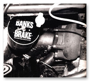
Step 13 Install the Banks Brake assembly onto the outlet side of the turbocharger, using the original bolts. Torque specification for the bolts is only 62-inch-pounds! Not too tight, but there is no way we were going to get the torque wrench into this cramped area. We simply tightened the bolts by feel.
“Installing the Banks Brake vacuum pump and wiring harness, and performing the Banks SmartLock installation took Modesto a total of about four hours”
Step 14 Clamp the upper portion of the turbine outlet pipe onto the outlet of the brake assembly using the original turbine-outlet V-band clamp/ ON TRUCKS BUILT FROM 1999-UP, POSITION THE V-BAND CLAMP AS SHOWN IN THE INSTRCTIONS TO PROVIDE ROOM FOR TIGHTENING. We did not read the above directions in Step 14 and, hence, we had more difficulty!
The beginning of our difficulty with Steps 13 and 14 were not due to inattention to the directions, but because of our inexperience with this installation and the poor access to this part of the engine and turbocharger. Although we did install the Banks Brake and thread the 12-point 8mm bolts into the turbine housing as directed in Step 13, we did not tighten these bolts yet as past experience has taught us that fitting connecting parts first, like the Banks down-pipe, and keeping everything loose or hand tight is often advisable. Reaching and tightening the turbine bolt in the 10-o’clock position was hard, but the bolt just below this one is even more difficult when it came time to tighten it.
The V-band clamp that we spent so much time trying to loosen during Step 5 again became our nemesis. In the tight confines of the rear of the engine where the turbocharger and Banks Brake live, there is little room to operate. Modesto and I were careful not to over stretch the V-band clamp while getting it around the down-pipe and the Banks Brake mating points. Just getting the clamp properly positioned around the Banks Brake and the down-pipe was a pain.
After getting the clamp around these parts, we needed to get the T-end of the clamp bolt back into its slot on the end of the clamp. This was a small struggle, with Modesto under the truck pushing on one end of the clamp with a long screwdriver while I was getting scraped up inside the engine bay trying to put the “T” back into the clamp. After the clamp was basically in place we noted that the nut on the clamp was not in a spot that would allow for tightening (because we didn’t read the instruction carefully). With the clamp in place but still loose, it was very hard to rotate around the outlet pipe and Brake to provide access to the tightening nut. After much struggling and swearing we did manage to rotate the clamp counter-clockwise a little to a position that we thought would allow for easy tightening. We were wrong.
Because we had the nut on the end of the V-band clamp approximately 180-degrees from where the Banks directions state it should be, we had a bear of a time getting a tool onto this nut. This oversight caused us to struggle for another 45-minutes to tighten the nut on the end of the clamp which was almost hidden below the bottom of the Banks Brake. I was again force to struggle with a box-end wrench in the tiny space, moving the nut a fraction of a turn at a time. I finally made the clamp tight, and we moved onto the final step, Step 15.
Step 15 On trucks 1999-up, install the support bracket using the supplied bolts. This support bracket attaches to the rear of the engine block and to the front of the Banks Brake to support its extra weight. Because of our improper positioning of the V-band clamp, we were not able to attach this support bracket. Modesto was thinking of having a substitute bracket fabricated, but because of the difficulty we had already experienced (do-it-yourselfers always learn the hard-way) we did not want to take everything apart and start over. At the late hour we were finishing this portion of the installation, we did not know why we were having problems, simply that we needed to stop for the night.
The above installation took us about seven hours after subtracting that time we spent taking a lunch break and making our tool run. I assume that Banks could do it in half this time (or less) and that an experienced professional shop would be much quicker as well. But, we did it ourselves and lived to tell about it.
Phase Two
After a good night’s sleep Modesto continued the installation the next morning without my help. He reconnected the intercooler tubes and buttoned-up the loose ends we had left the night before. Mo installed the vacuum pump, hoses and wiring for the Banks Brake which he said was quick and easy. He said the installers should be careful to route the Banks wiring and vacuum hoses away from the down-pipe, Mo said he used lots of zip-ties for this purpose. Then Modesto installed the Banks SmartLock.
The SmartLock installation went well, as Modesto is quite skilled when comes to wiring (see your Banks instructions for the step-by-step), he did note a few areas where he had a little difficulty.
Step 13 includes locating the brake validation switch and revealing the two wires connected to the switch and isolating the black wire with the yellow tracer. Make a cut in the wire about two-inches away from the connector. After stripping each end of the wire, crimp the male and female spade connectors supplied onto the wire ends with a crimping tool. These are simple instructions for a simple task although Modesto noted that the wire in question is short, and it is hard to reach to crimp. Because of the poor access this step took him about 45 minutes.
On Step 18, when it was time to mount the SmartLock “box” Mo used glue in addition to the foam tape provided by Banks to help secure the module in place. He also found it helpful to plug-in the harness first (Step 19), and then mount the box, which is a little out of order.
Step 22 involves locating and tapping into the RPM signal wire. The wire is located below and slightly towards the driver’s side of the brake master cylinder on the firewall. To reach the wire on Modesto’s 2000 Power Stroke Mo had to squeeze his hands between the master cylinder and a fuse/relay box. Access is tight, and it is hard to see the wires and what you are doing. The goal is to locate the white wire with a pink tracer. Possibly due to age and weathering, the closest match Mo could find was a yellow-looking wire with a pink tracer. Modesto even had a couple of neighbors come over and look at this wire to get their opinion of the color of the wire. Eventually Modesto decided that this was the correct wire and connected as indicated using a T-tap connector. Mo had found the right wire and everything worked when it was time to perform the function tests.
Installing the Banks Brake vacuum pump and wiring harness, and performing the Banks SmartLock installation took Modesto a total of about four hours. Again, with above average experience and tools, a couple of good do-it-yourselfers can do the whole job in a weekend (or less). Not a bad investment when you consider the money you save by not paying someone to do the installation and the experience you’ll have about how accessories are installed on your vehicle.
It’s All About Results
Excellent workmanship and instructions are great, but how do the products work? Mo hooked up his car trailer to find out. A trip to our local certified CAT scale told us that Modesto’s 2000 Limited Edition F-350 weighed 8,060-pounds solo; his 2000 Pace 24-foot tandem axle enclosed car trailer with Mo’s highly customized 1995 Chevrolet Impala SS low-rider (complete with hydraulics) inside weighed 8960 (tongue weight was 900-pounds), for a gross weight of 17,020-pounds. Although the car trailer has electric brakes on it’s axles, this is a heavy load that screams for an exhaust brake, especially since it is driven throughout the mountainous West. Just prior to our installation, Modesto had returned from a trip over the Colorado Rockies, and he was very ready to have an exhaust brake added to his rig.
Modesto took his 17,020-pound load up to the top of the famous Donner Pass in California’s high Sierra’s and drove down into the mountain town of Truckee, California. The first test was preformed using Modesto’s new found “Whoa Power”, the Banks Brake and the SmartLock.
From the rest area at the 7239-foot summit Mo accelerated onto the freeway until he hit about 65-mph in over-drive (4th), then flipped the toggle switch to engage his Banks Brake (which also activates the trans SmartLock). His truck and trailer quickly slowed to 50-mph. The combination stayed at or near 50-mph for the remainder of the trip down the mountain; Modesto never applied his brakes once and kept the transmission in fourth gear. Modesto said toward the bottom of the hill he had to accelerate as his Banks Brake was slowing him more than was needed as the hill leveled off. Mo was very impressed and later, when I asked him how he liked his new Banks Brake, he stated “Awesome”!
The second part of the test was scary. Modesto drove back up to the top of Donner Pass and repeated the test. He accelerated up to 65-mph and released the accelerator; the Banks Brake was not activated. Mo left the truck in overdrive (O/D) again, because we needed a true apples-to-apples comparison, and he did not shift down to third. Modesto enjoyed the ride of a runaway train.
Mo said his rig quickly accelerated up and over 70-mph which was clearly too fast for his load combination. Modesto was trying to be conservative with his brakes, in an attempt to conserve as much braking power as possible for the miles of downhill ahead. Modesto applied his service brakes (trailer brakes, too, automatically) and slowed his combination to below 60-mph, only to have the rig rapidly accelerate past 70-mph again. This was not a surprising action for a heavily loaded truck and trailer traveling downhill in overdrive. Mo said that after traveling only a short distance and having made a few brake applications he started to experience brake-fade. Most of us know what a terrible feeling it is to find that we have little or no braking control remaining.
After this graphic display, Mo said he would not be without an exhaust brake simply because of the safety margin it provides when hauling heavy loads. Now he can save his brakes for stopping his rig, as he will rarely have to use them to slow or maintain a particular speed on hills. Mo said that his transmission temperatures were 25-30 degrees cooler too.
Modesto is now one happy Tow Master who is now avoiding disaster.