
Jay to Gale: Hey, Can You Banks This?
Jay Leno’s tank car Gallery #2: Intake manifold construction

The AV 1790 Hemi is an air cooled 90-degree V12 with cylinder banks over 50 inches long and a 42 inch width across the rocker covers. Because of Gale’s concern for thermal expansion in such a long engine, and for ease of manufacturing and assembly, we decided to make our intake manifolds as three-piece sections with a floating o-ringed coupling sleeve between each section.
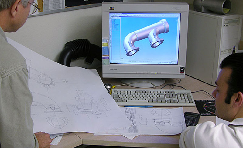
Before work can begin on the intake manifolds, a general layout of all new engine components must be developed. Both board and CAD drafting methods were employed to create the layout and individual component drawings. Here Chief Designer Bob Robe and CAD Drafter Michael Robinson discuss the intersection geometry for one of the intake manifold sections. All intersections were CNC machined for a precise fit during welding.

We selected forged aluminum elbows with an internal diameter that closely matched that of the intake ports. Tapered transition tubes were machined that incorporated end sockets to accept the o-ring coupling sleeves. Because our design utilizes manifold sections that repeat identical features and dimensions, we built modular tooling for weld fixturing and alignment. Fabricator Michael Markowitz admirably completed the task of welding all the pieces together with show-quality beads and minimal distortion.

Our turbocharger system design features a single throttle body feeding the center of the intake manifold log on each side of the engine. Bob checks the fit of the elbow sections that comprise the center manifolds. All of the manifold components were styled to reflect the late forties/early fifties engine design and to complement the vehicle’s styling.
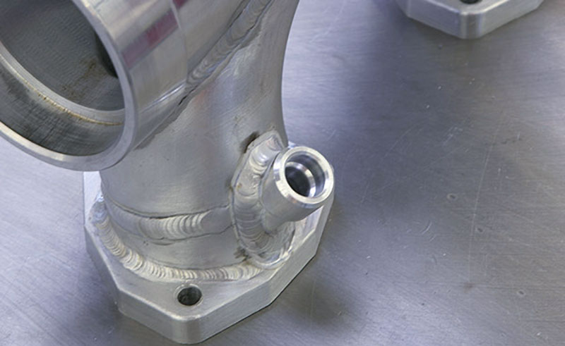
Fuel injector nozzle placement can be critical to proper combustion and throttle response, but is often limited by other physical components on the engine. Our nozzle bosses are located to target the backs of the intake valves while maintaining clearance to the rocker box drain fittings and other features.

Once the manifold components were welded together, the flange faces had to be surfaced and squared to equalize the flange-to-centerline dimension on all six manifolds. Our modular weld fixture now converts to a mill fixture so our Okuma CNC machining center can take over.
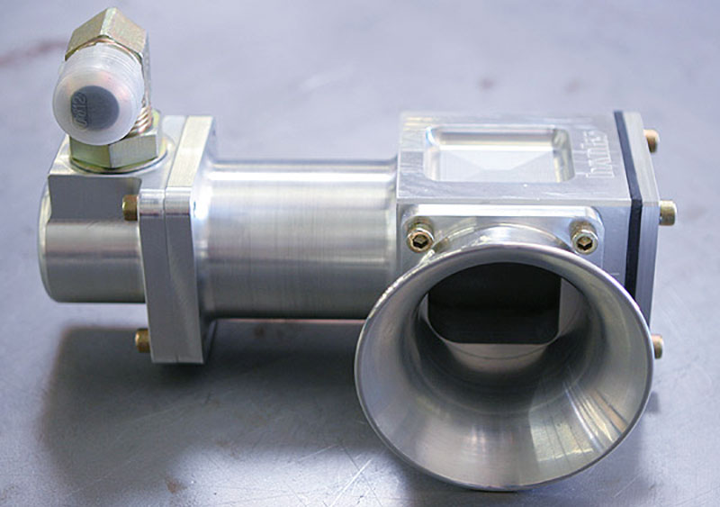
When Jay gets on and off the throttle, and back on it again, he wants those Honneywell/Garrett turbos to react NOW! Our Banks turbo system will include a pair of Gale’s custom-built shuttle valves to blow off boost air that stacks up against the throttles when they are suddenly closed. Without the shuttle valve pressure relief, the turbos will slow down, resulting in lag if the driver suddenly opens the throttles again. An additional benefit is a reduction of compressor surge with throttle closing. The valve works so well that Jay had us make one for his twin-turbo Toronado!

A two-foot long spring compressed within the valve body holds a piston closed against a relief port to atmosphere. Pressure differential across the closed throttle will overcome the spring pressure to open the valve. A 3/4-inch diameter line (for fast response) references the back of the piston to the manifold on the downstream side of the throttle.

All of the shuttle valve components are machined from aluminum in one of Banks’ CNC machining centers. The pistons are turned and then hard anodized to resist wear. Here Prototype Machinist Shawn Collins sets up one of the rough-turned shuttle valve bodies prior to facing operations. In our next installment, we’ll look at the fuel rails that feed this thirsty beast!