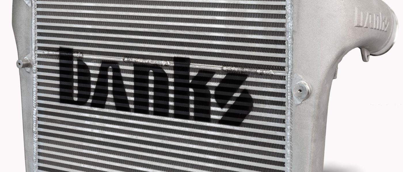
97766 Intercooler Upgrade for 2010-2012 RAM 6.7L Cummins
INSTALL INSTRUCTIONS
Part #s
25539
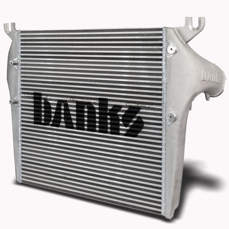
Banks Intercooler System 2010-2012 RAM 2500/3500 6.7L Cummins
Do not attempt to install before you have depressurized your A/C system. The A/C system will need to be recharged post-install.
Please read through the following instructions thoroughly before starting your installation. If you have any questions please visit our Support Page.
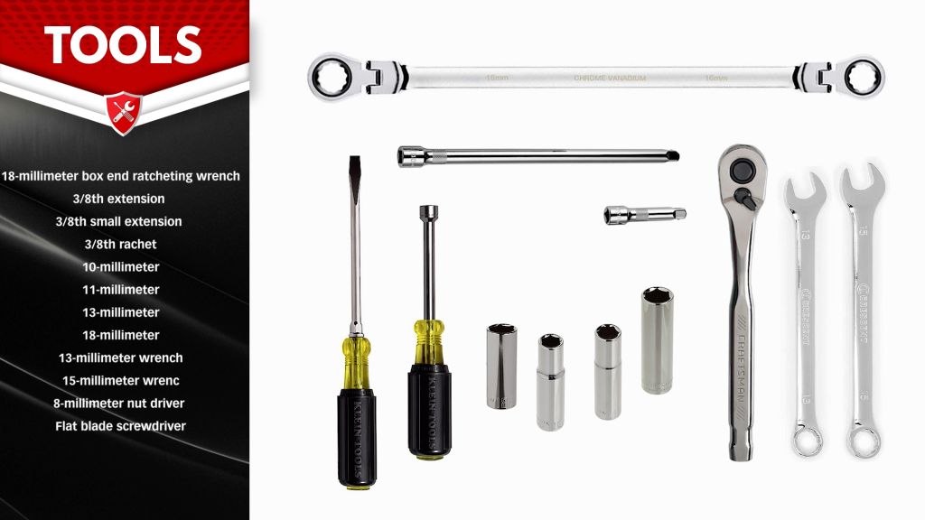
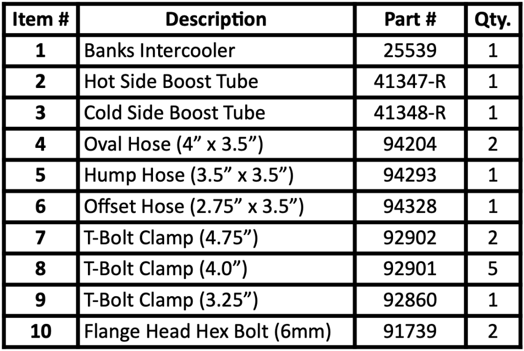
Bill Of Materials
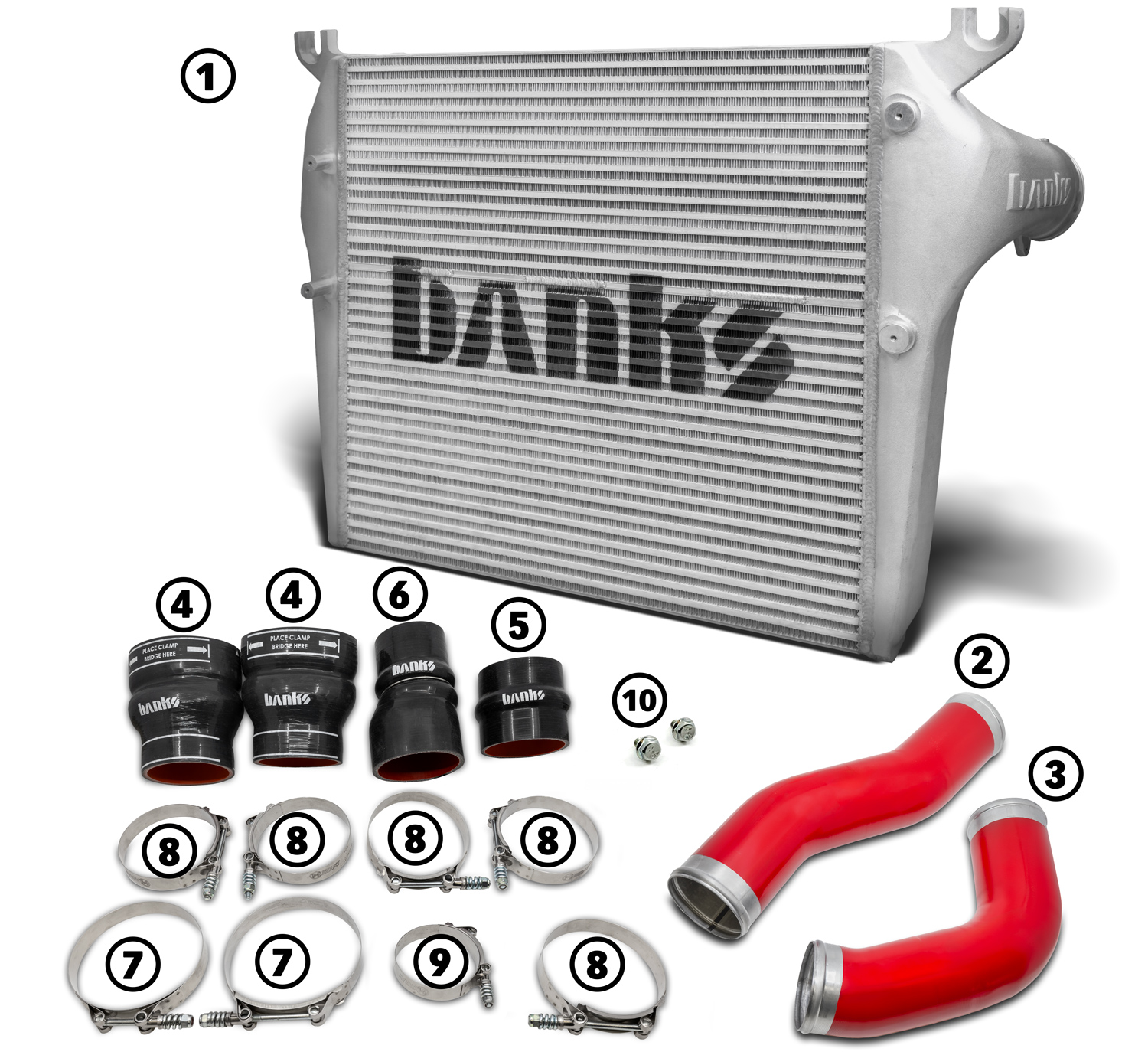
Note: A/C Discharging & Transmission Fluid.
In order to access the charge air cooler on a 2010-12 RAM 6.7L, you’ll need to remove the combination A/C condenser and transmission cooler which is mounted directly in front of the charge air cooler.
While the transmission fluid can easily be drained from the cooler and topped off after installation, the A/C lines are under pressure. The refrigerant must be recovered from the A/C system by a licensed technician, and the system must be recharged after installation.
Before proceeding with the installation, have your A/C system discharged.
Section 1: Factory Intercooler Removal
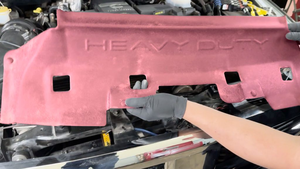
1. Lift up the core support cover that sits above the radiator and free its push-clips.
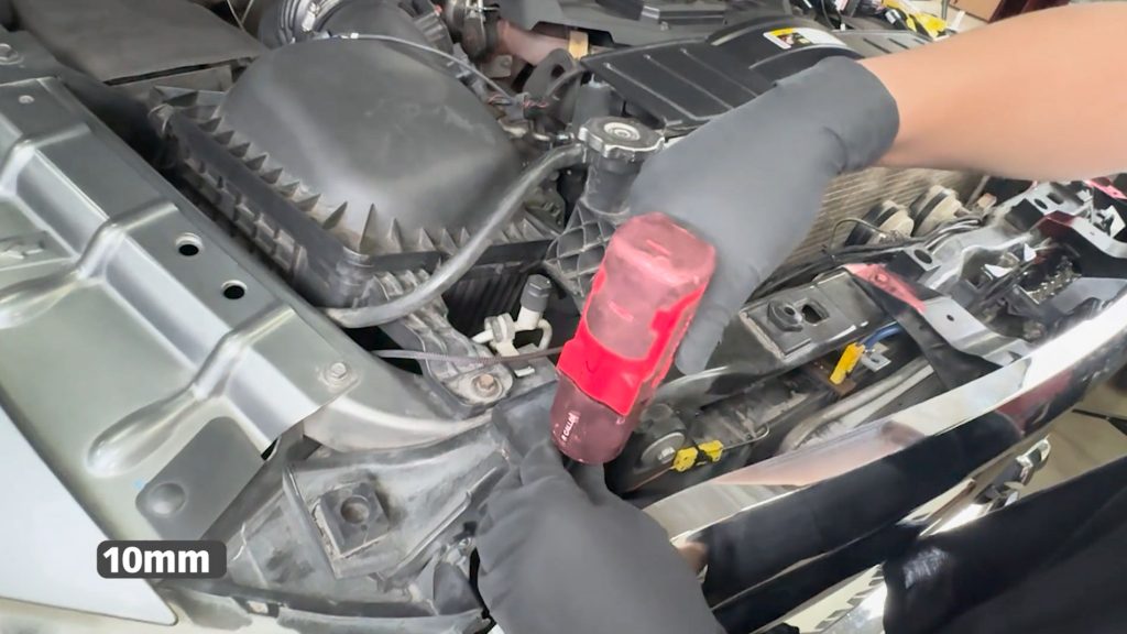
2. Remove the four 10mm bolts that hold on the Grille.
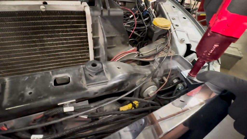
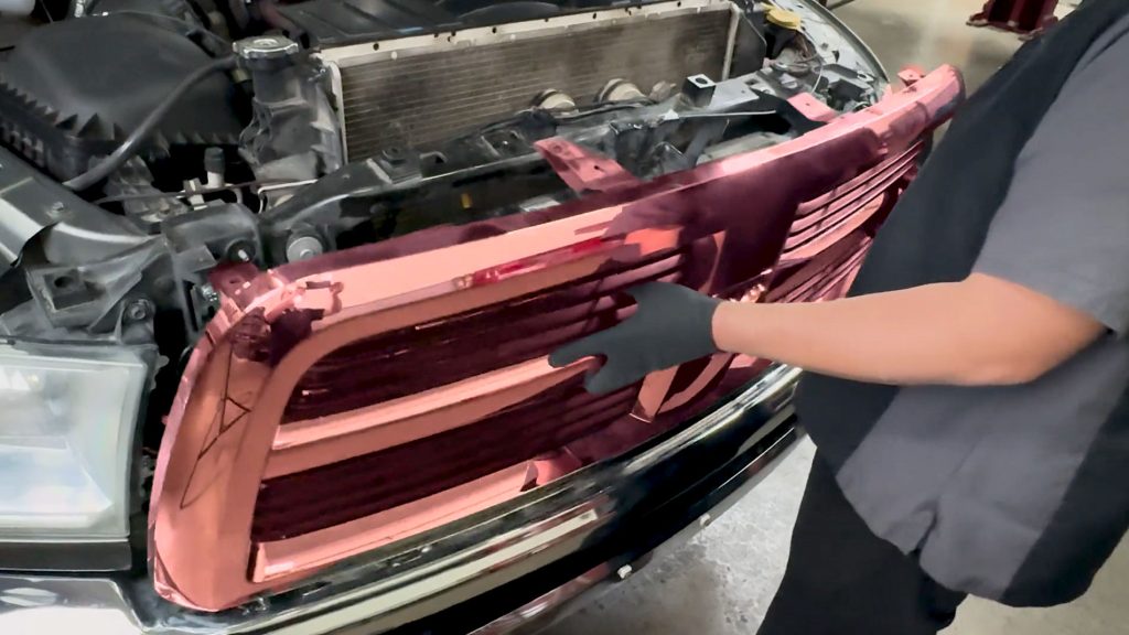
3a. Lift to remove the Grille and set it aside.
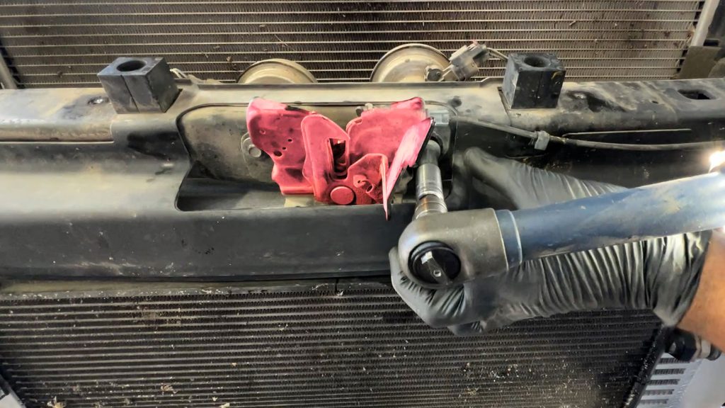
4. Remove hood latch by removing two 10mm bolts. Cable can remain connected. Move latch to the side.
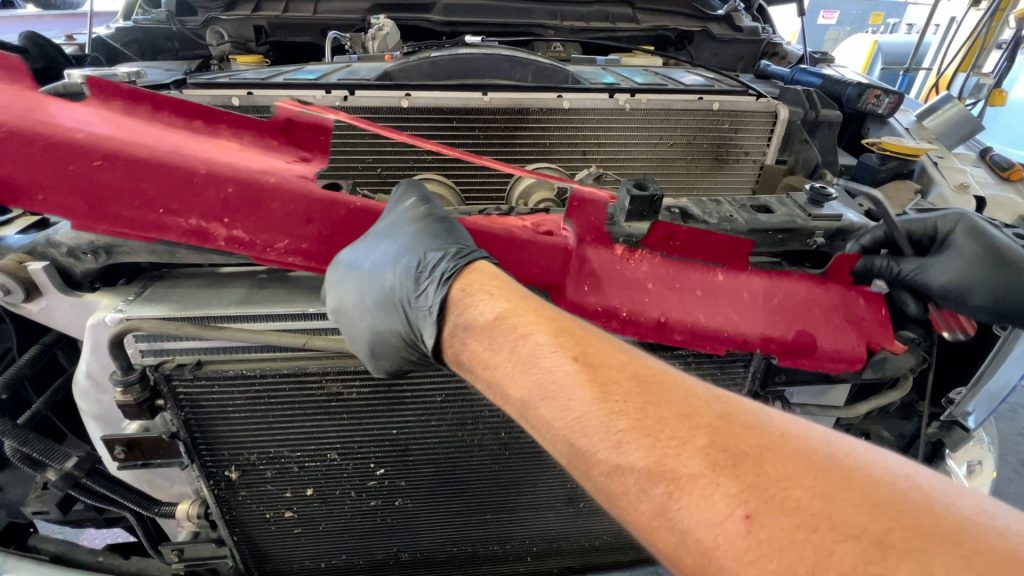
5. Remove radiator shroud by removing two plastic push-pins. Set aside. You will put this back on later.
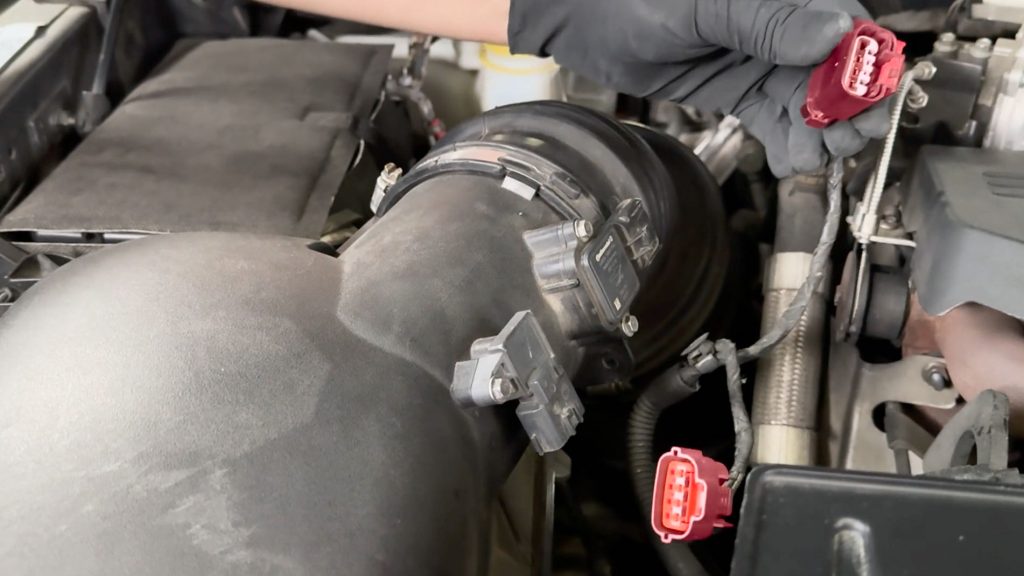
6. Release the red locking clips on the Intake Pressure and MAF sensors and unplug them.
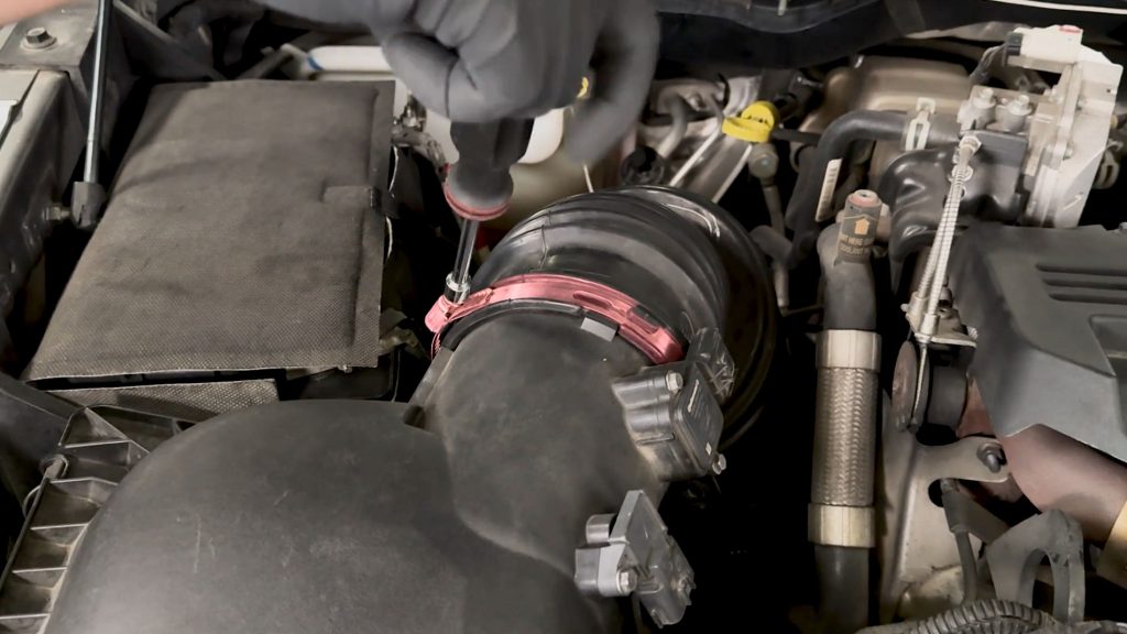
7. With a Flat Head Screwdriver or 8mm nut driver, release the clamp on the airbox.

8. Do the same for the lower clamp on the turbo inlet.
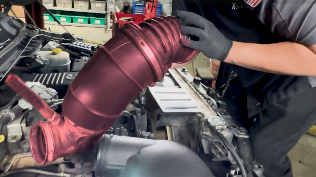
9. Wiggle the intake duct free and set it aside.
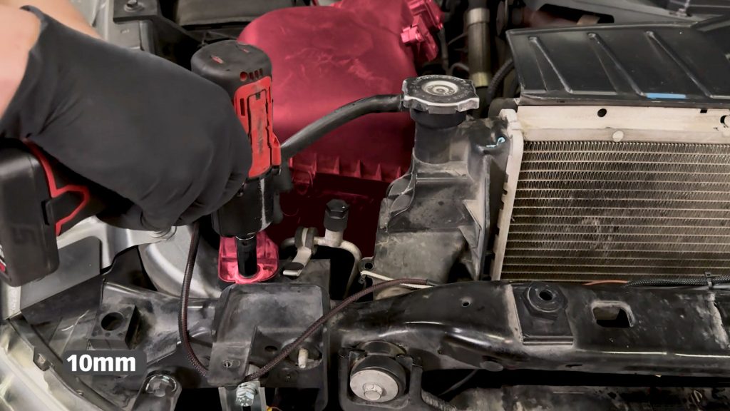
10. Remove the 10mm bolt that secures the airbox.
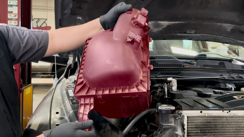
11. Lift and remove the airbox and set it aside. It is held on with a grommet on the bottom that will pop free.
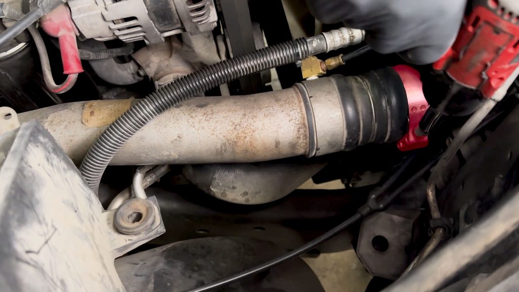
12. With a 11mm socket, loosen the clamp connecting the OEM boost tube to the intercooler inlet.
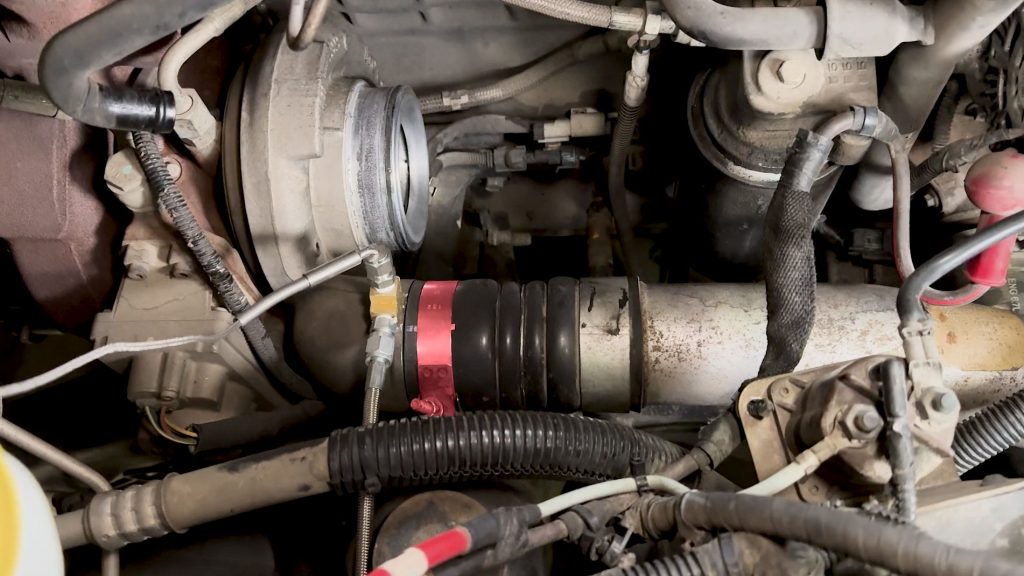
13. Do the same for the clamp on the turbo compressor outlet side.
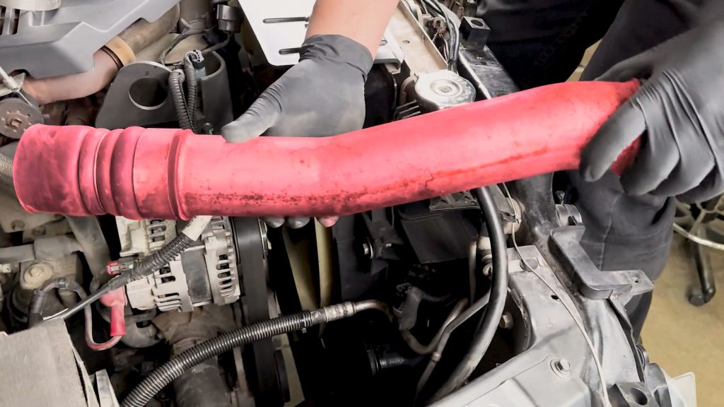
14. Wiggle free and remove the factory hot side boost tube, and set it aside.
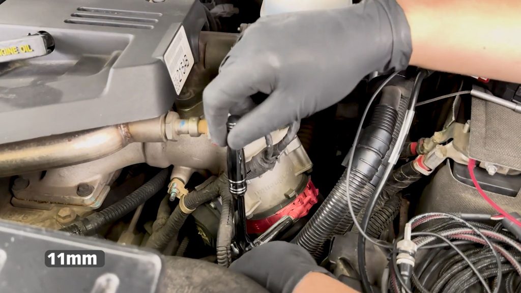
15. With a 11mm socket, loosen the upper clamp on the factory cold side boost tube.
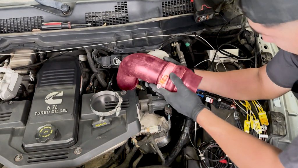
16. Do the same for the lower clamp. Remove the factory cold side boost tube and set it aside.
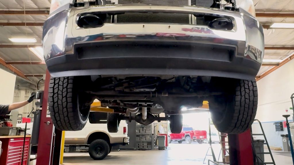
17. Raise the truck up on a lift.
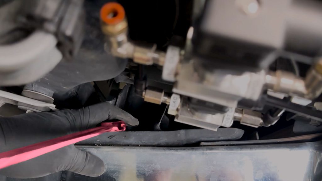
18. With a long 18mm flex head ratchet, loosen and remove the two nuts securing the front bumper.
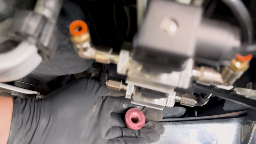
Do the same for both sides
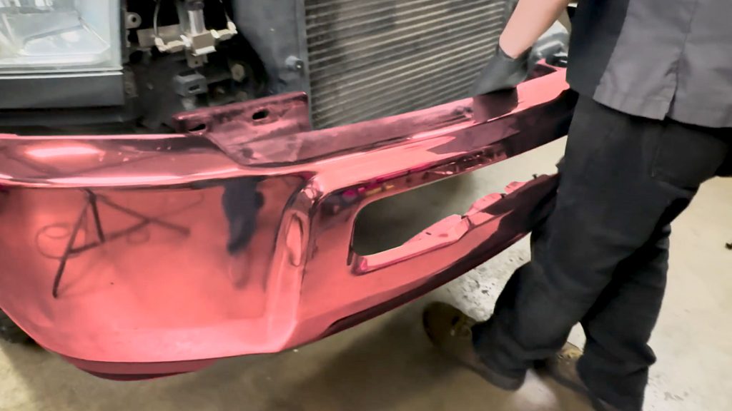
19. Carefully lift, remove the front bumper, and set it aside.
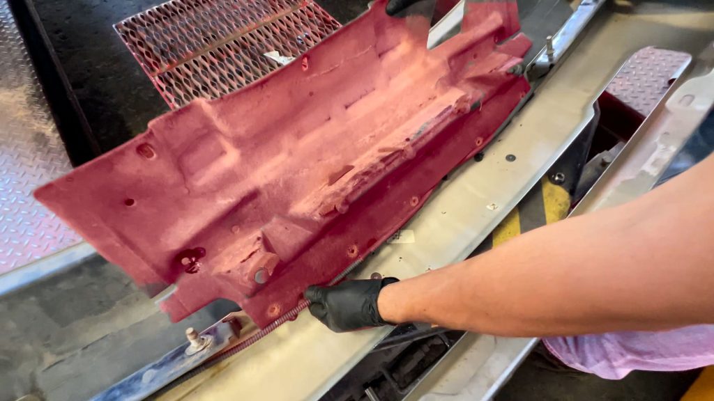
20. Remove and discard plastic shroud affixed to inside of bumper.
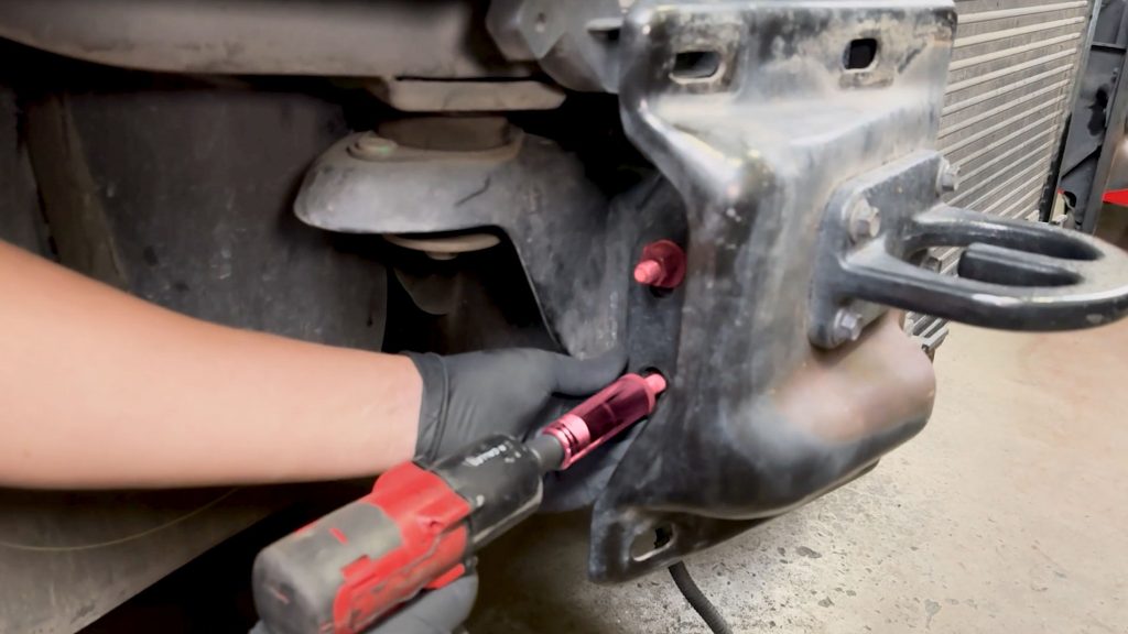
21. With a 18mm socket, remove the 2 nuts holding the front tow hook.
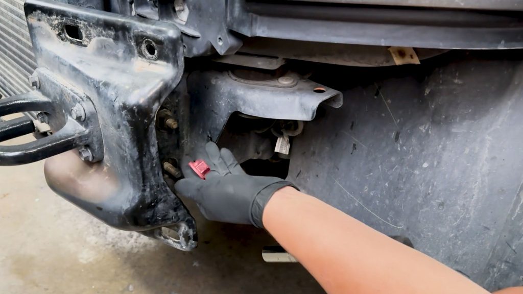
Do the same on the other side and set the two tow hooks aside.
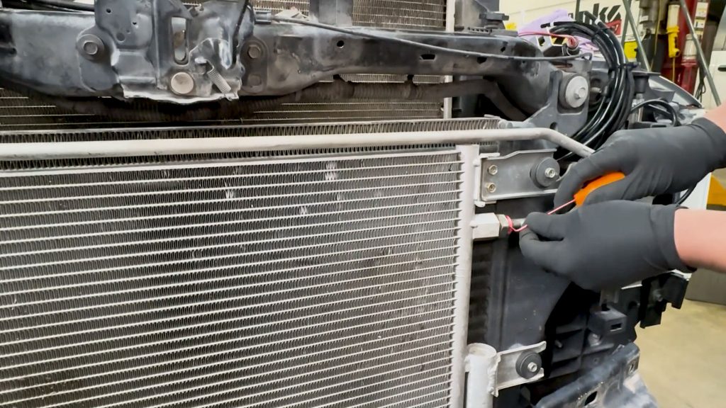
22. With a pick tool, carefully remove the c-ring holding the transmission cooler hard line.
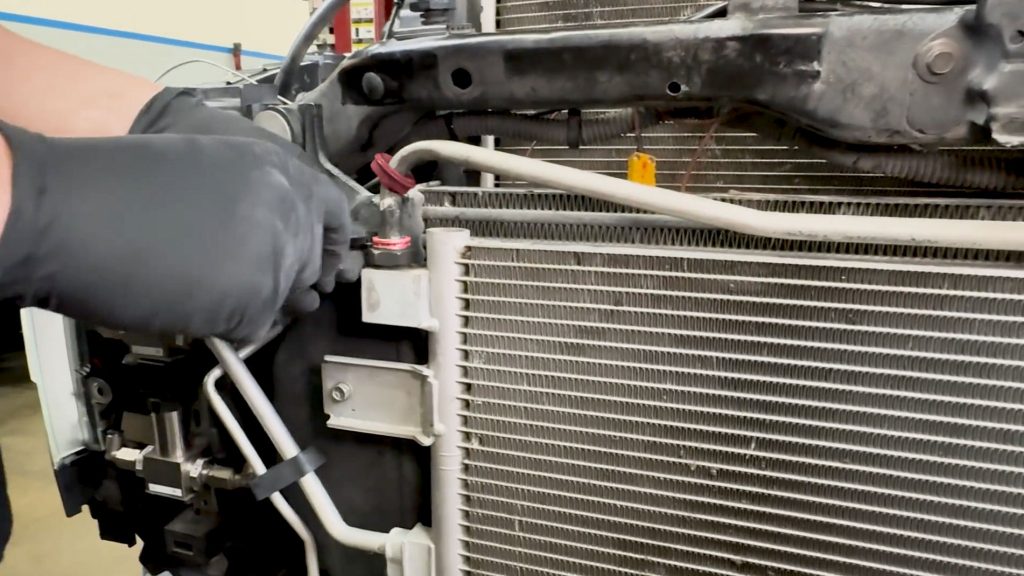
Do the same on the other side.
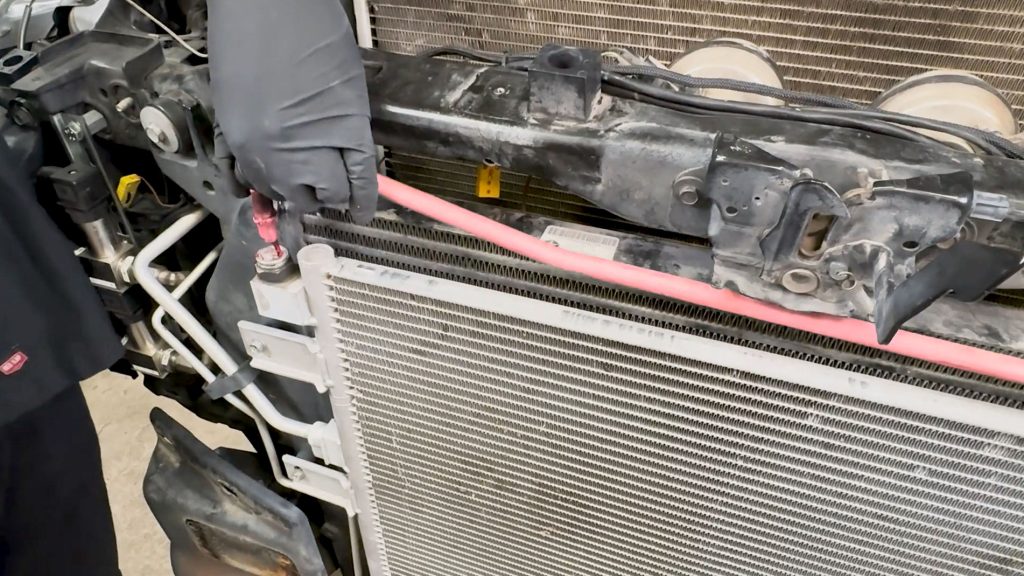
Carefully lift and free the hard-line; some liquid will leak out.
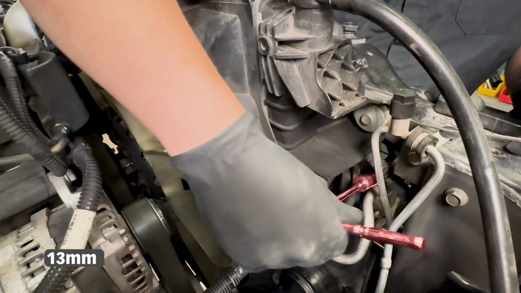
Loosen and disconnect the upper and lower A/C hard lines with a 13mm socket. This will free up the cooler/condenser.
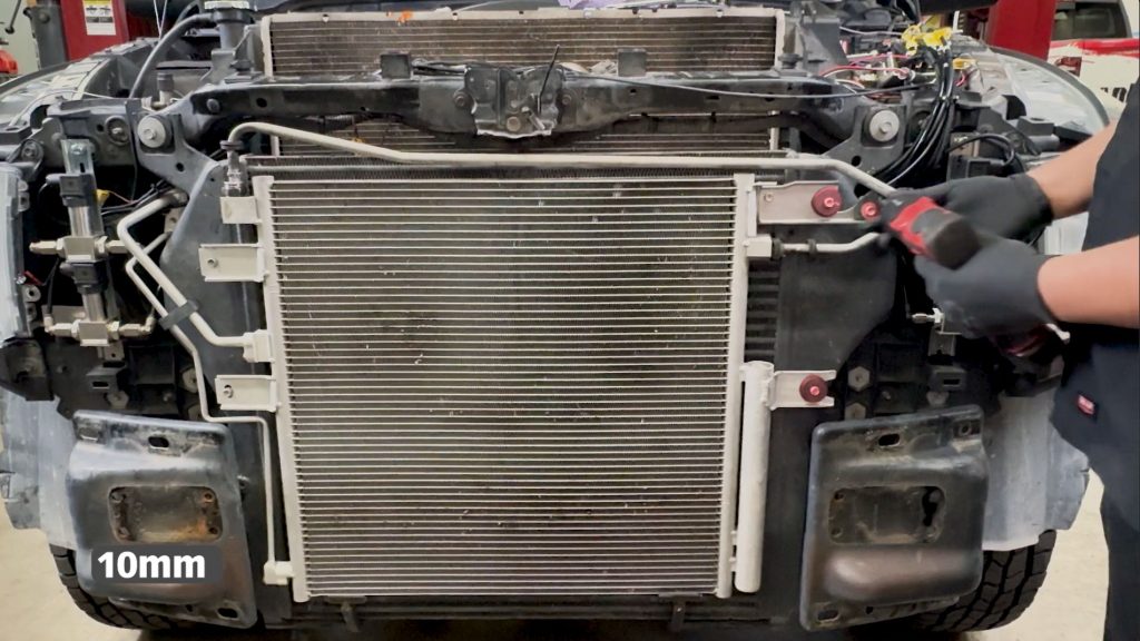
23. With a 10mm socket remove the 3 bolts on the driver side of the condenser.
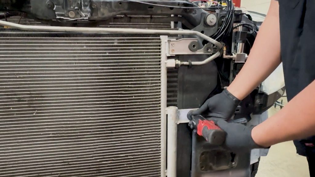
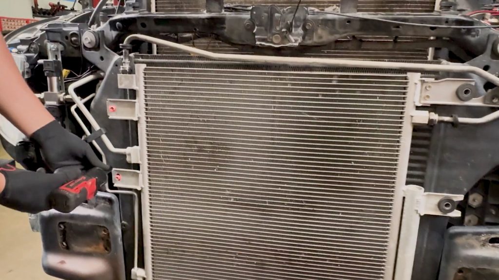
Do the same for the 2 on the other side.
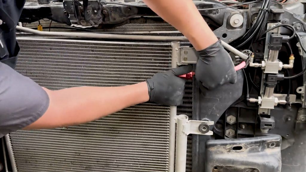
24. Pop the driver side transmission hard-line free. Some fluid will leak out.
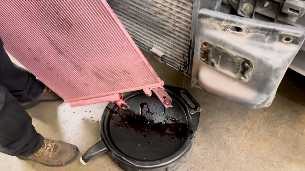
25. Tilt the unit over a bucket or drip pan to collect any fluid, and set it aside.
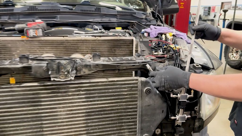
26. With a zip-tie, move and hold the hard lines up and out of the way for now.
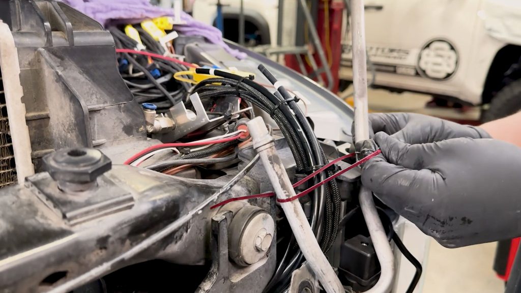
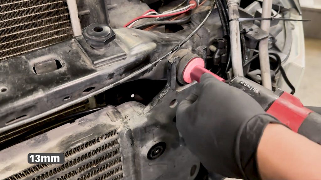
27. With a 13mm socket, remove the upper bolts holding the stock intercooler.
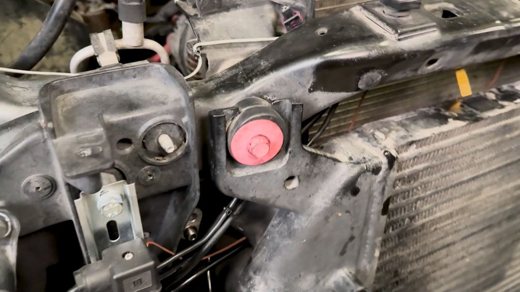
There is one on each side.
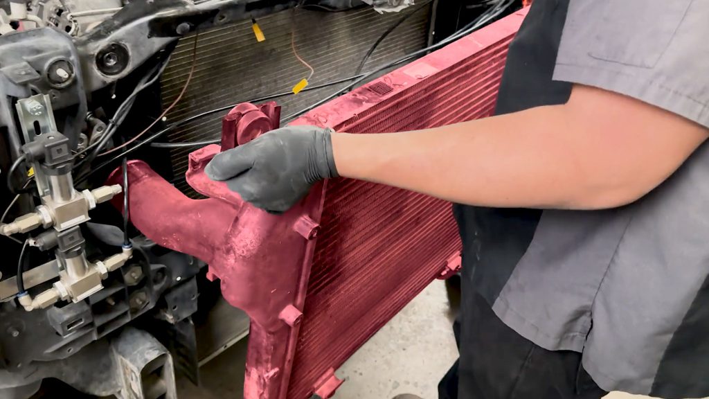
28. Lift to remove it and bring it to a work table.
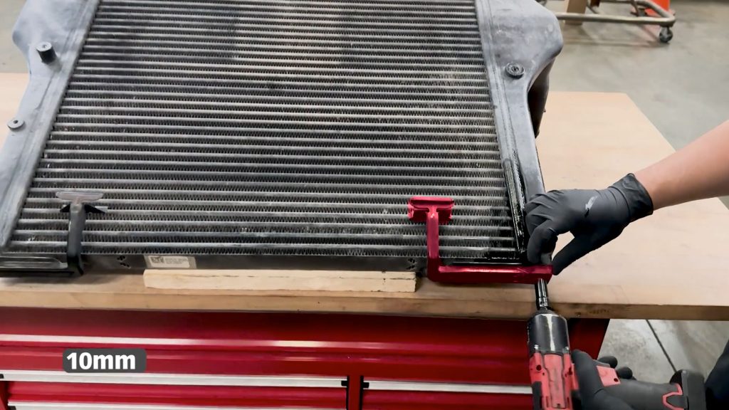
29. With a 10mm socket, remove the brackets that support the condenser / transmission cooler.
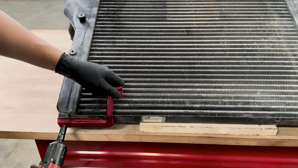
There is one on each side.
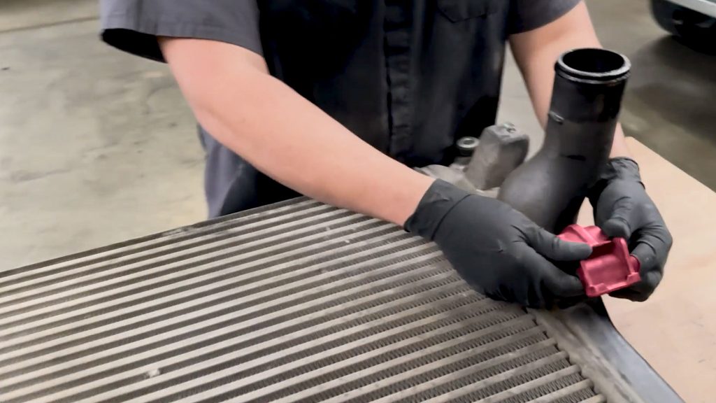
30. Remove the rubber isolators on the back side of the Charge Air Cooler.
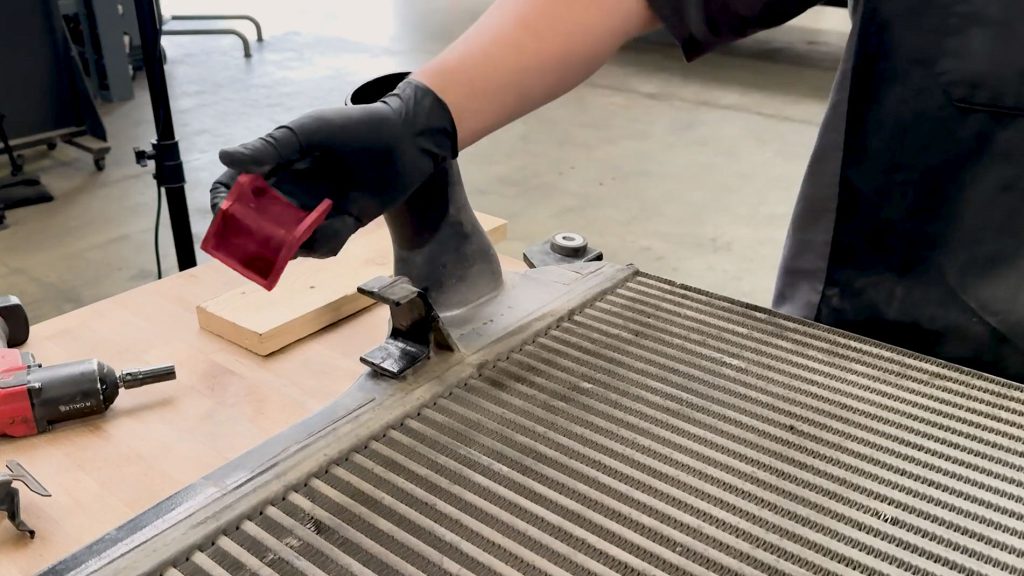
There is one on each side.
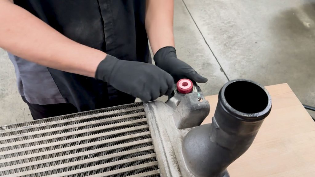
31. Remove the grommets on the bottom of the stock intercooler
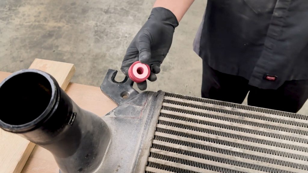
There is one on each side.
Isolator Modification – Where to cut and trim.
The lower factory rubber isolators have to be trimmed slightly to accommodate the larger Banks charge-air cooler. While the first 3 cuts are identical for the left and right side isolators, the final cut is a mirror of each other. With knife or sharp blade, use the shaded photos below as a guide and remove the extra material.
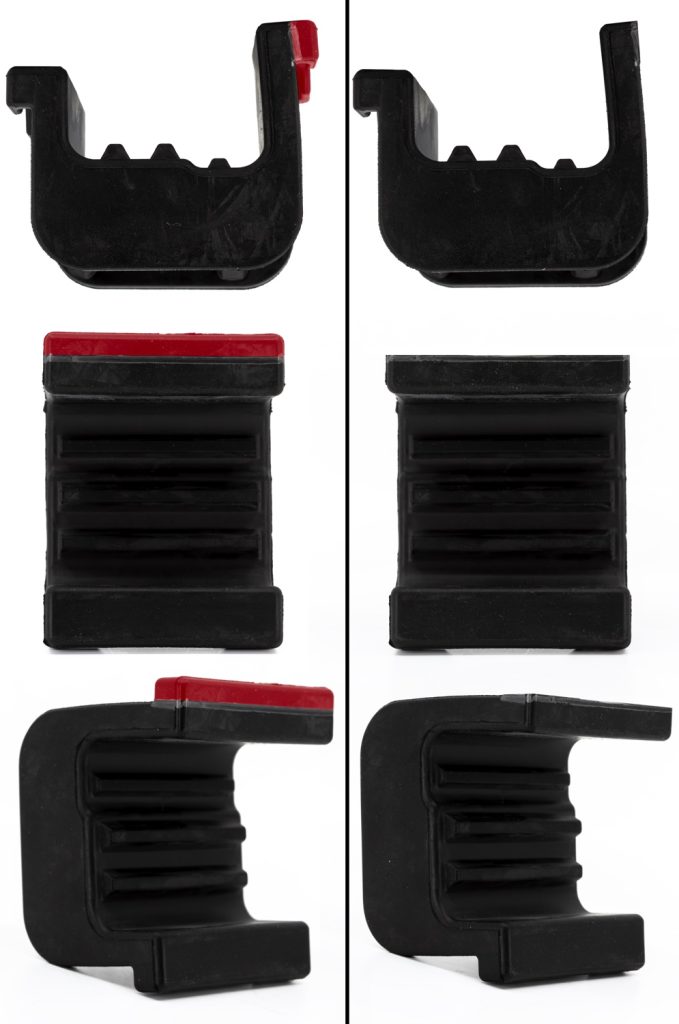
1. Trim the whole shaded protruding end off the longer side of the isolator.
Do the same for the other side.
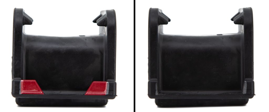
2. Trim the 2 shaded protruding ends off the short side of the isolator.
Do the same for the other side.
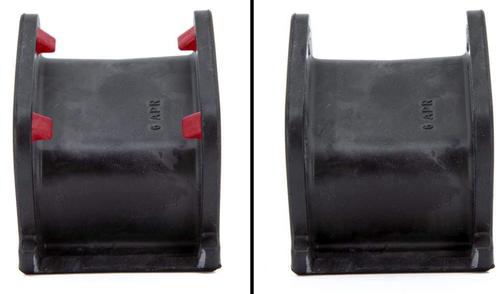
3. Trim the 4 shaded protruding ends from the top of the isolator.
Do the same for the other side.
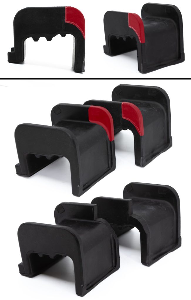
4. Following its curvature, trim the shaded corner from the long side of the isolator.
Mirror the cut on the other isolator, so that your two cut portions are inboard to each other.
Section 2: Banks Intercooler Upgrade Install
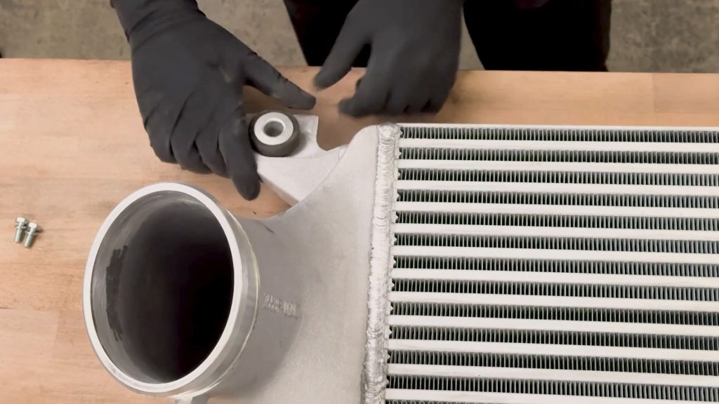
1. Transfer the rubber grommets onto the Banks Intercooler.
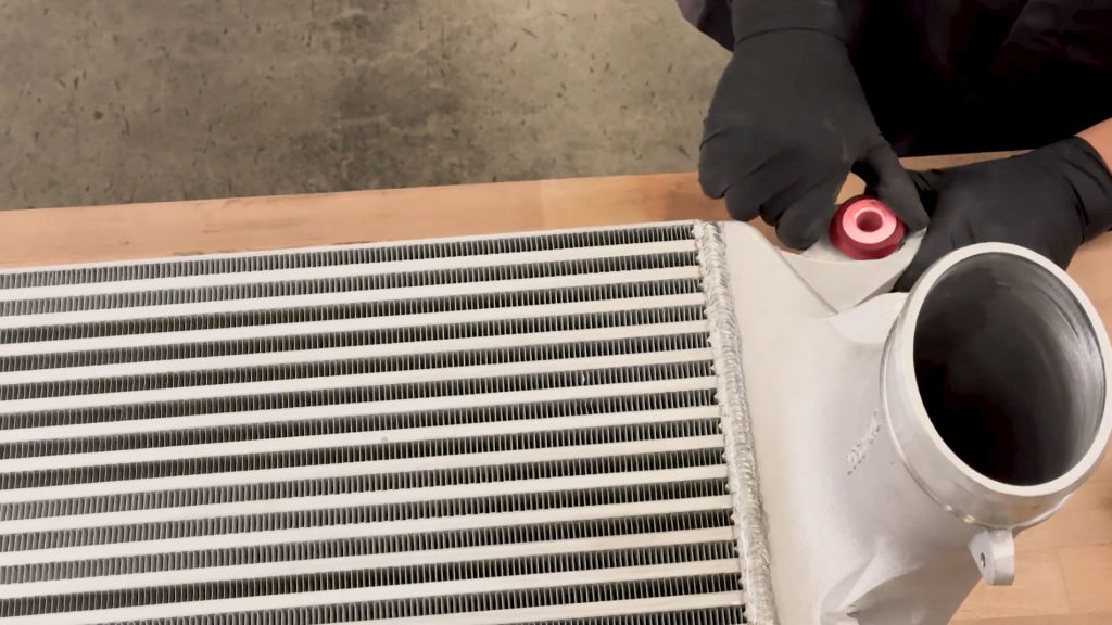
Do the same for the other side
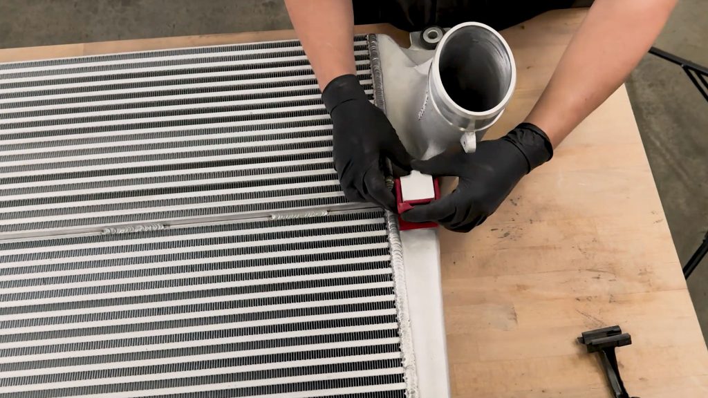
2. Transfer the rubber isolators onto the Banks Intercooler.
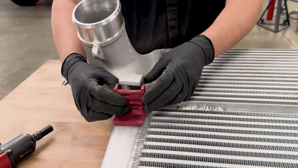
Do the same for the other side.
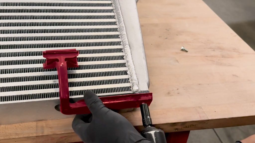
3. With a 10mm socket, transfer the A/C – Transmission cooler core support bracket to the Banks Intercooler.
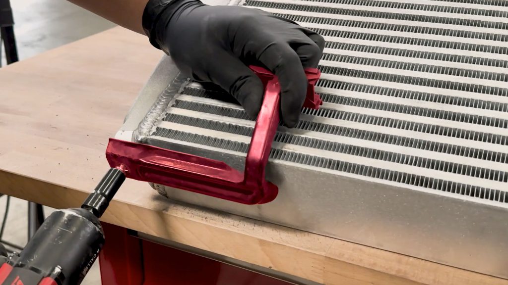
Do the same for the other side.
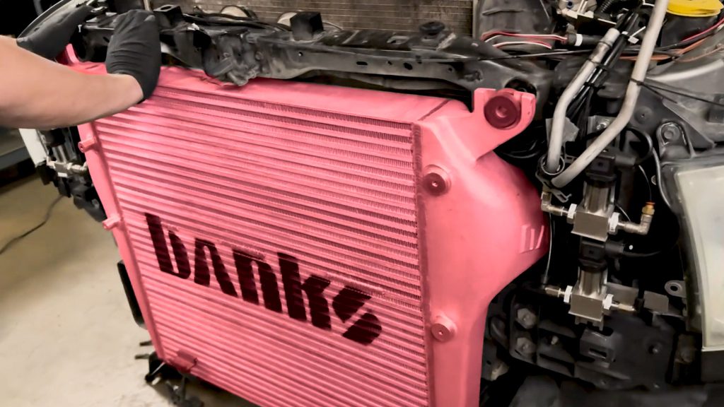
4. Carefully lift, and mount the Banks Charge Air Cooler onto the truck.
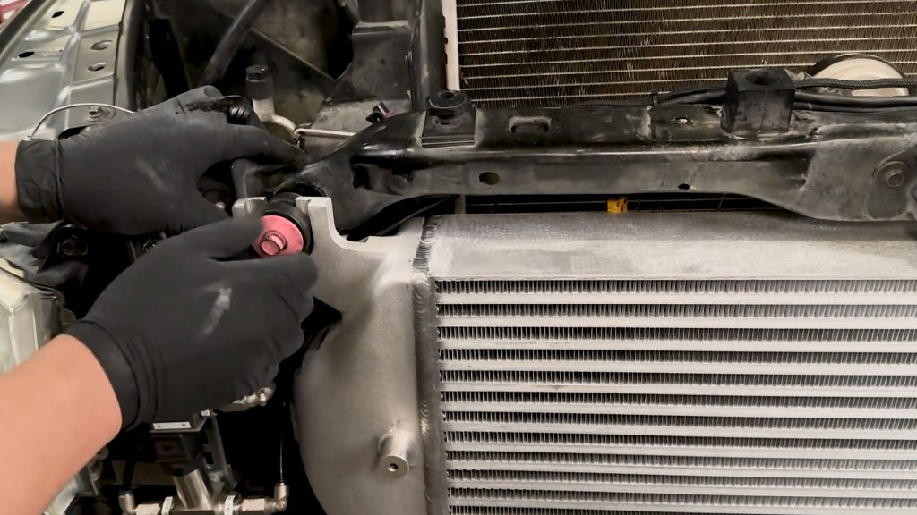
5. By hand, secure the two 13mm bolts on the top.
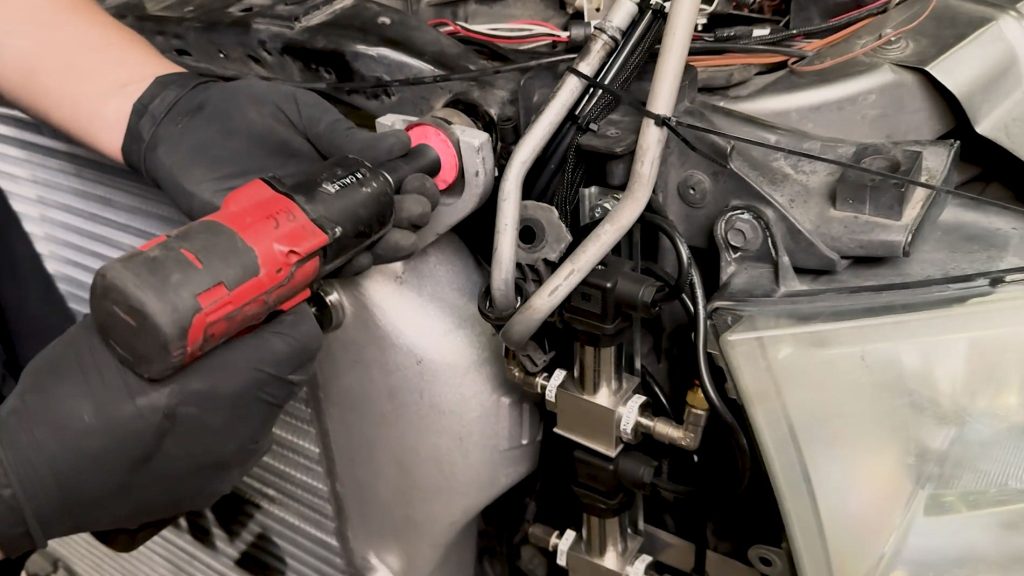
Then snug them down.
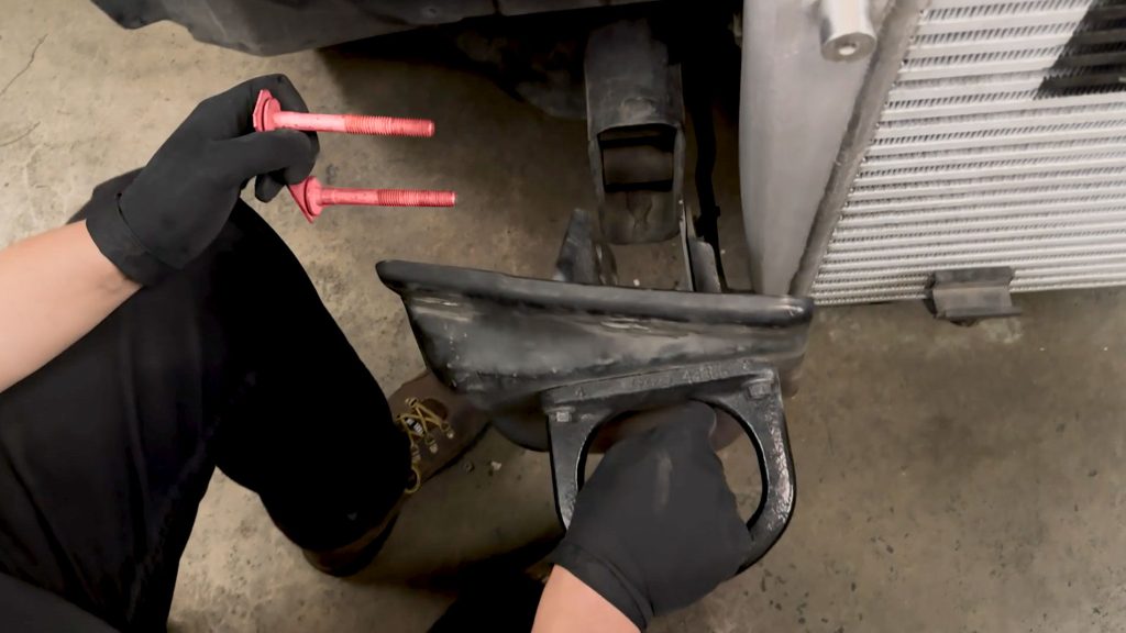
6. Reinstall the front tow hooks, the mounting bolt/bracket will be installed from the outside facing inwards.
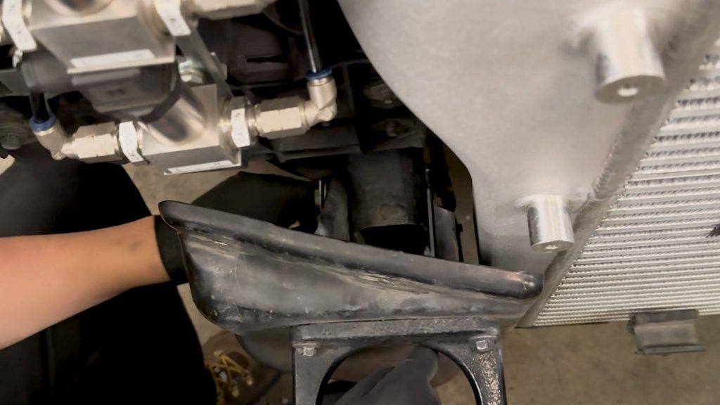
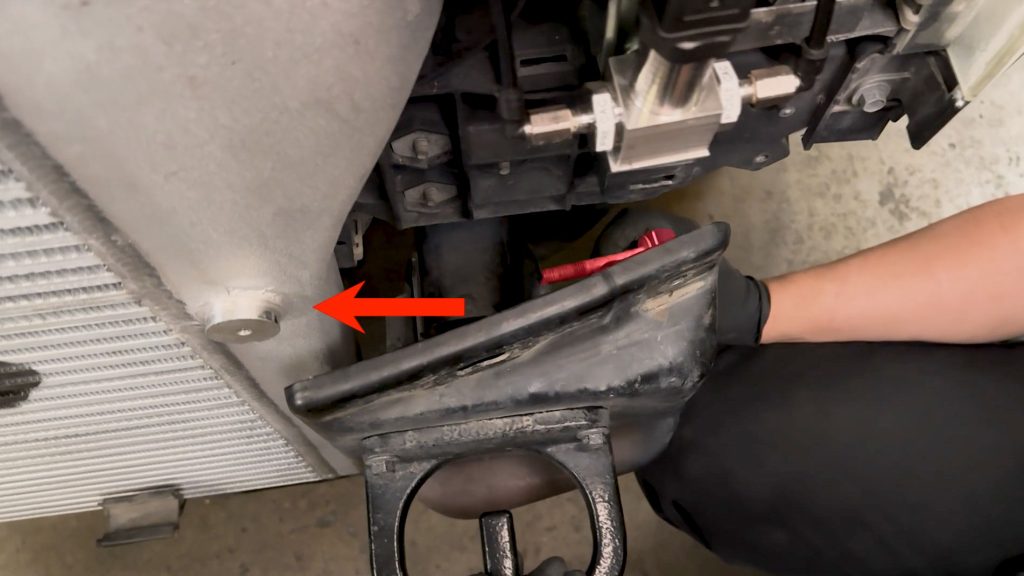
Do the same for the other side
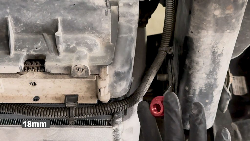
7. By hand, thread the two 18mm nuts for the front tow hooks.
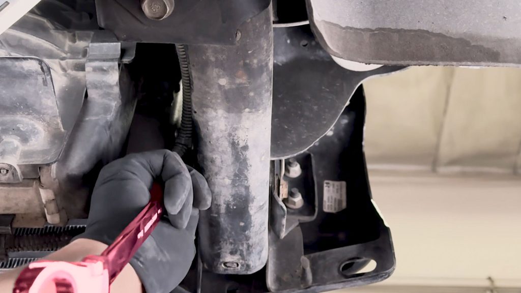
8. Secure the two 18mm nuts with a flex head ratchet wrench. Do the same on the other side.
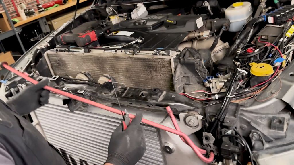
9. Cut the zip-ties holding the hard lines up, and lower them back down.
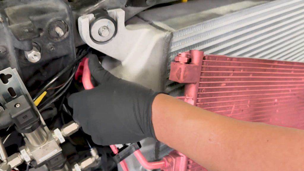
10. Bring the A/C Condenser / Transmission Cooler back to the truck, taking care to line up the A/C Hard Lines.
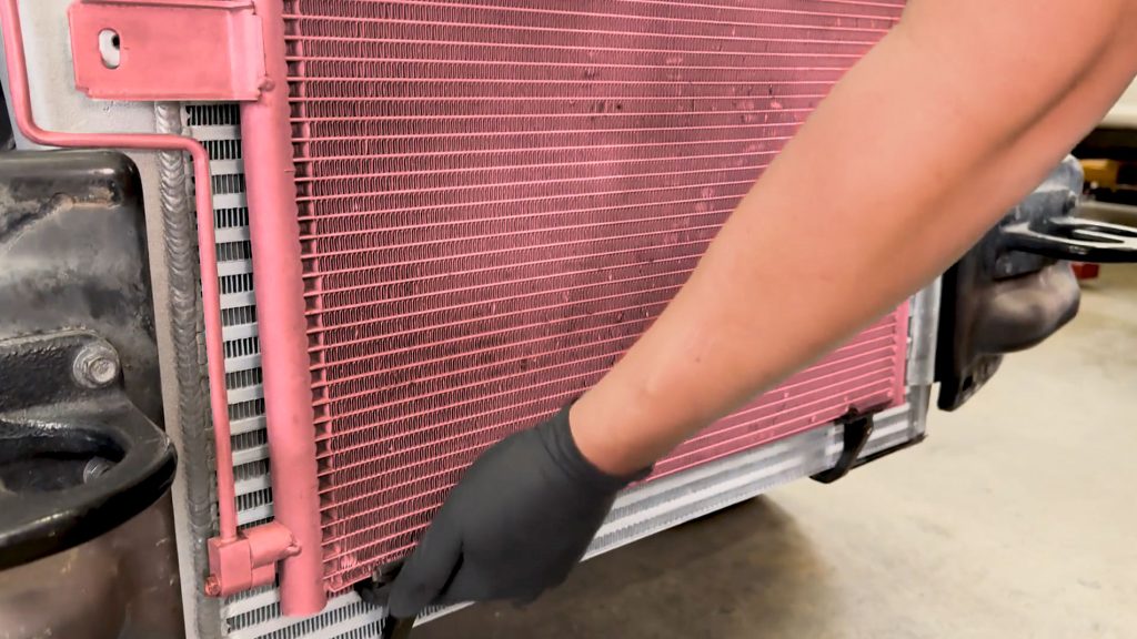
Check that it securely sits on the lower brackets.
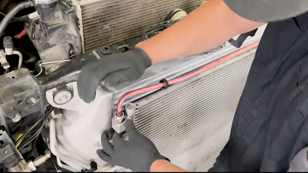
11. Lower the upper transmission hard-line onto the cooler.
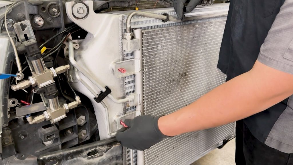
12. By hand, thread in the two 10mm bolts on the passenger side of the AC Condenser / Cooler.
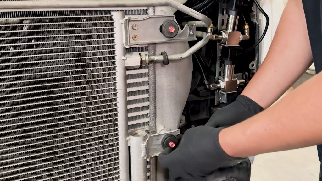
Do the same for the other side, they thread through two rubber grommets.
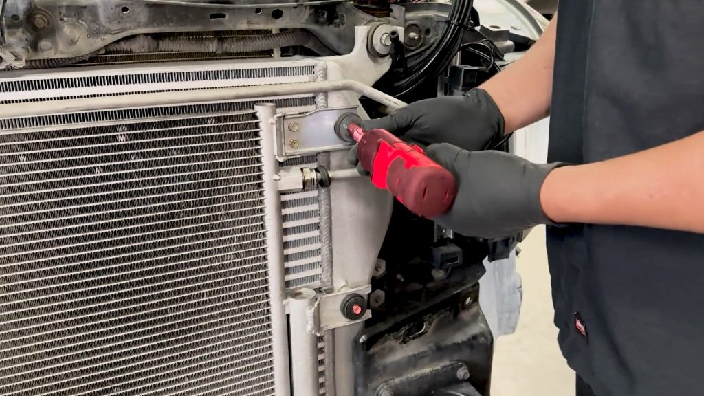
13. With a 10mm socket, secure the condenser/cooler to the Banks Intercooler.
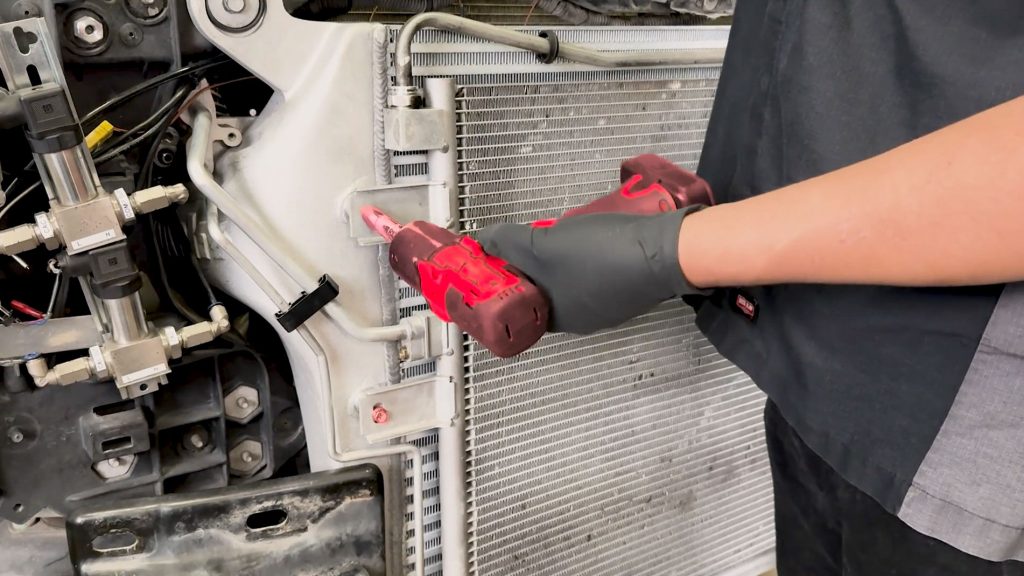
Do the same for the other side.
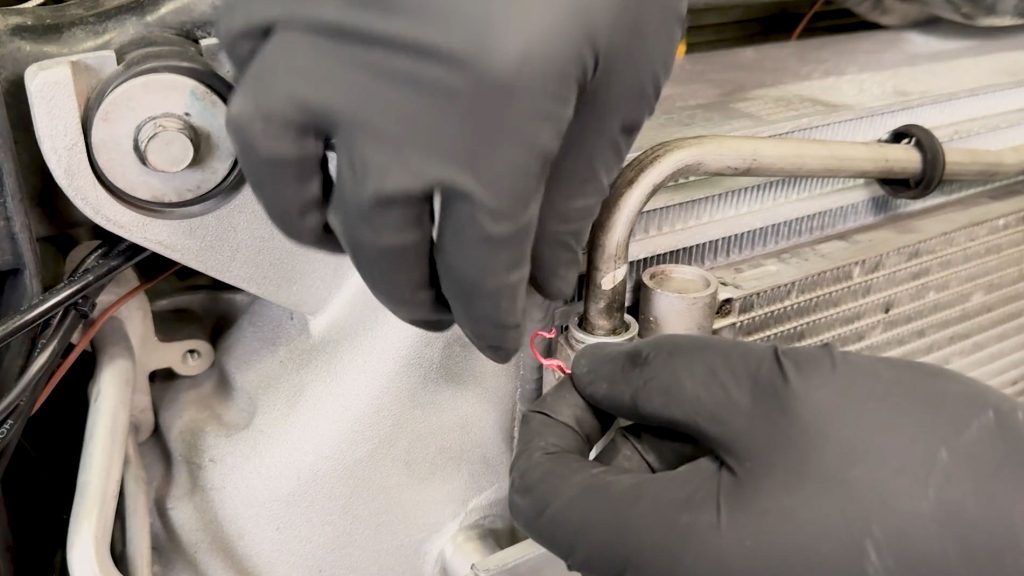
14. Secure the upper transmission hard line with the factory c-ring.
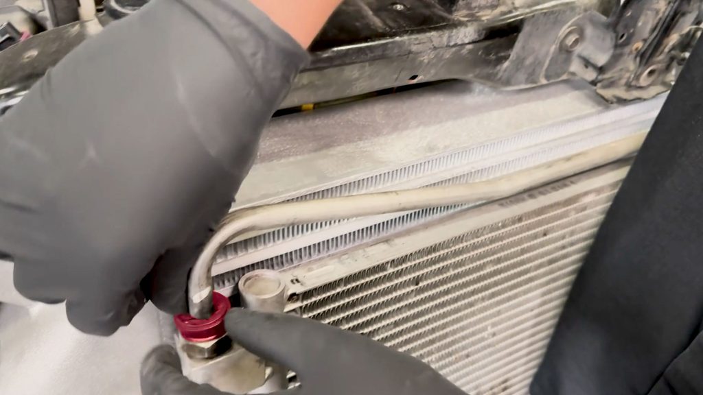
Slide and snap the upper cover back on.
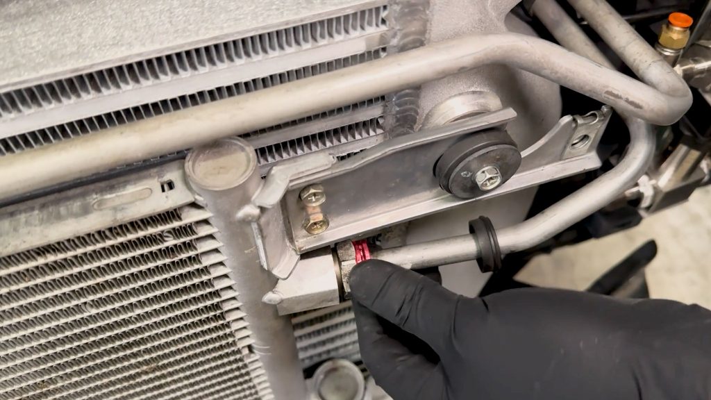
15. Secure the lower transmission hard line with the factory c-ring.
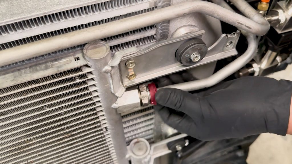
Slide and snap the lower cover back on.
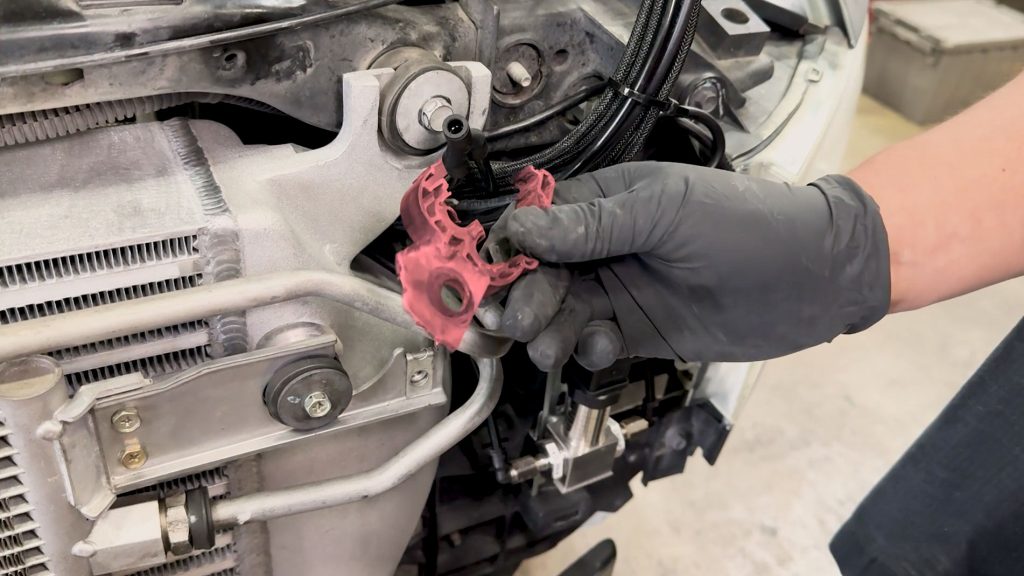
16. Reinstall the rubber transmission line support back in place.
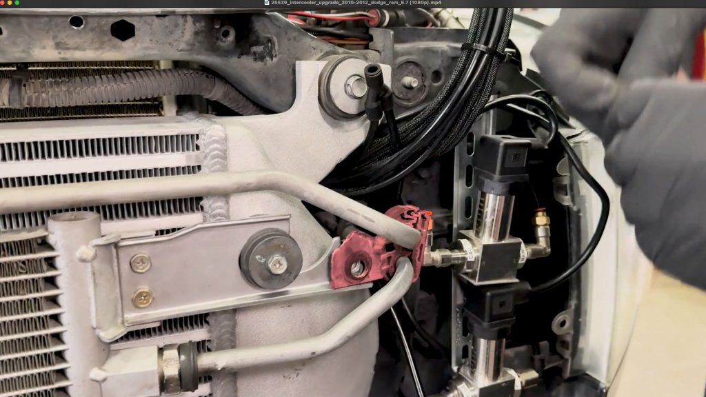
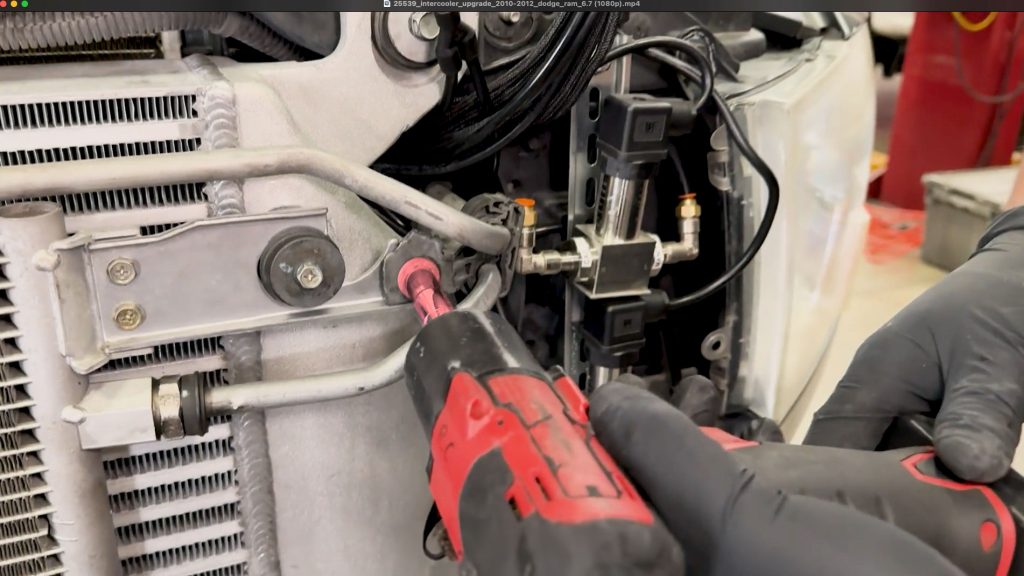
With a 10mm socket, secure it to the bracket to the condenser/cooler .
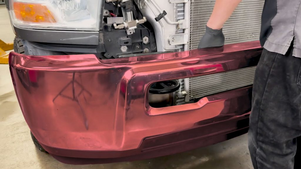
17. Carefully lift and reinstall the front bumper.
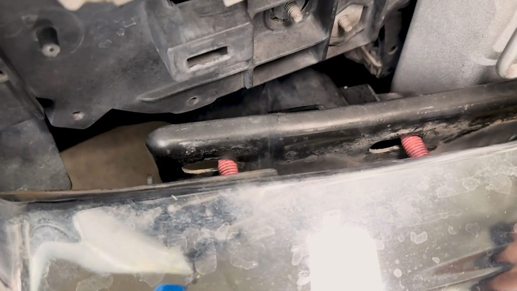
Be sure the line up the mounting studs.
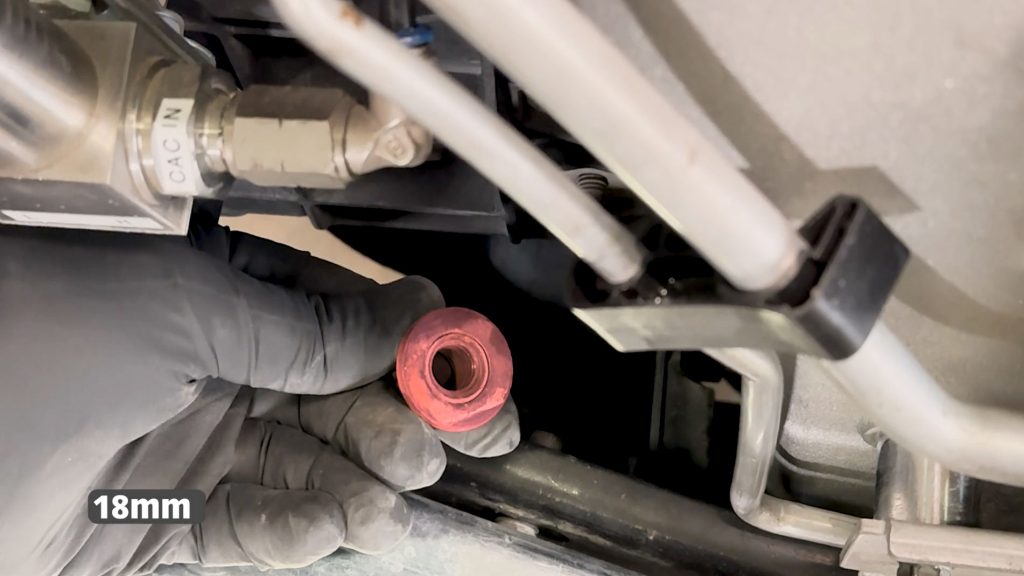
18. Reinstall the 18mm nuts that hold the bumper on.
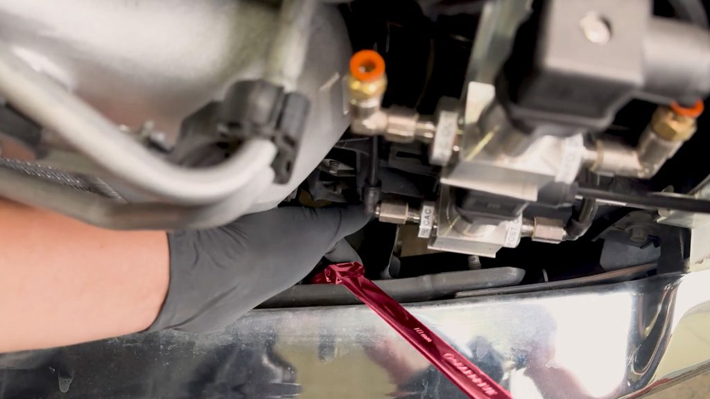
Secure the nuts on both sides with a 18mm flex head ratchet wrench.
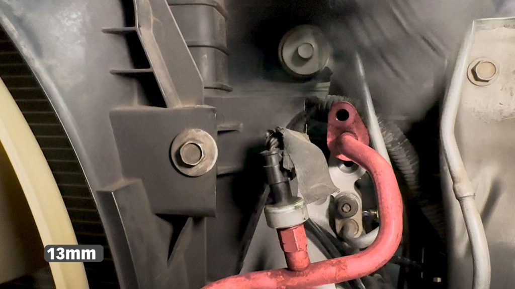
19. Locate and reinstall the the AC hard lines on the back side of the condenser/cooler.
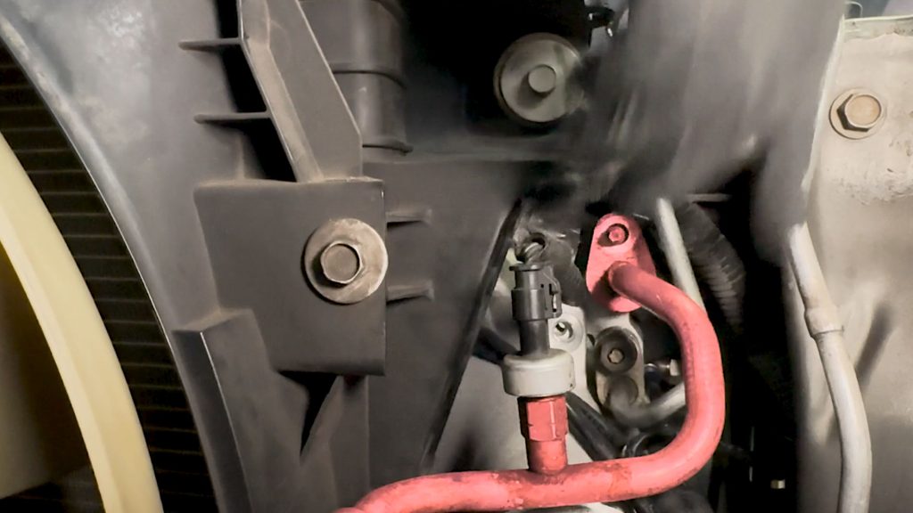
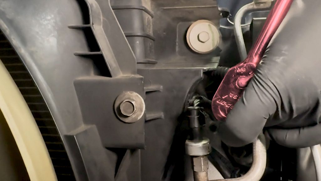
20. With a 13mm socket and extension, secure the hard lines.
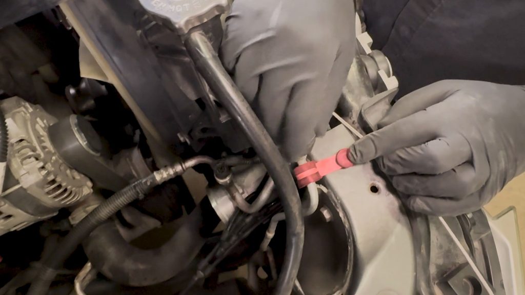
Be sure the press back in the upper tab back onto the front core support.
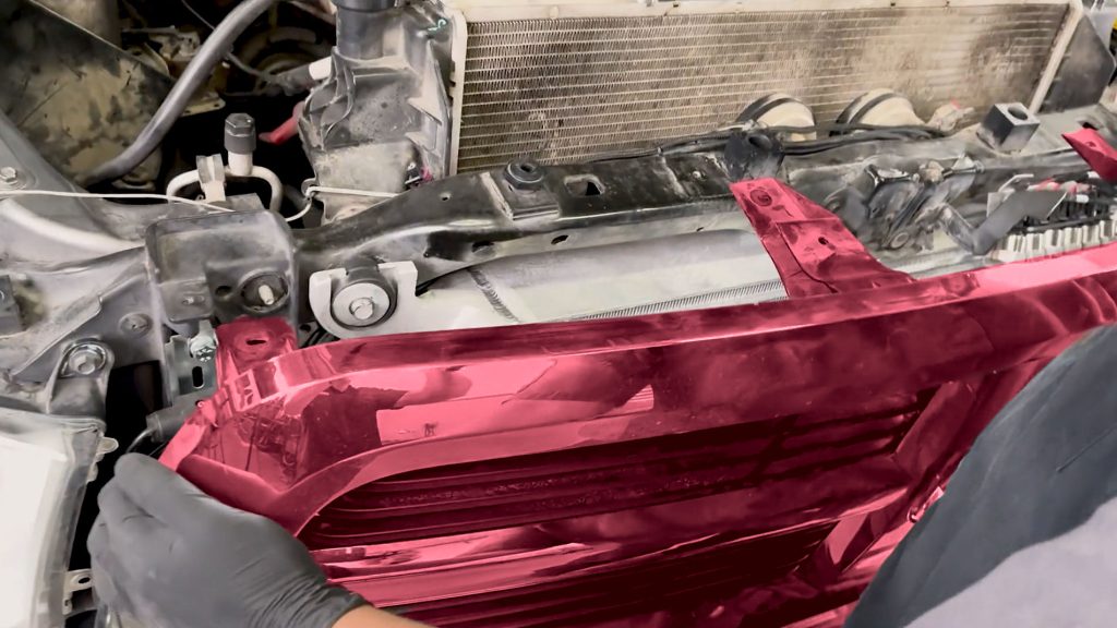
21. Carefully lift and reinstall the Grille
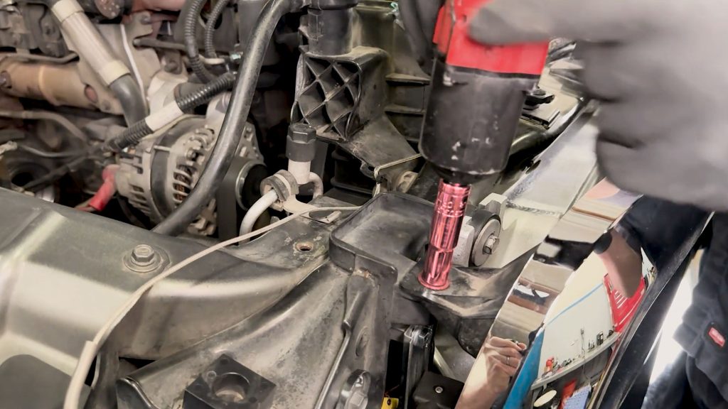
22. With a 10mm socket, secure the front Grille.
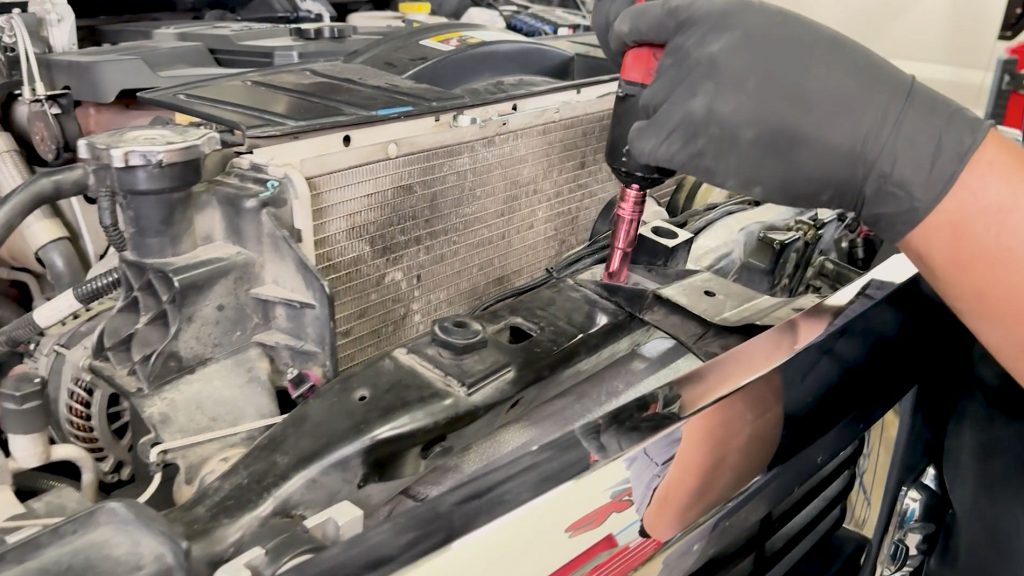
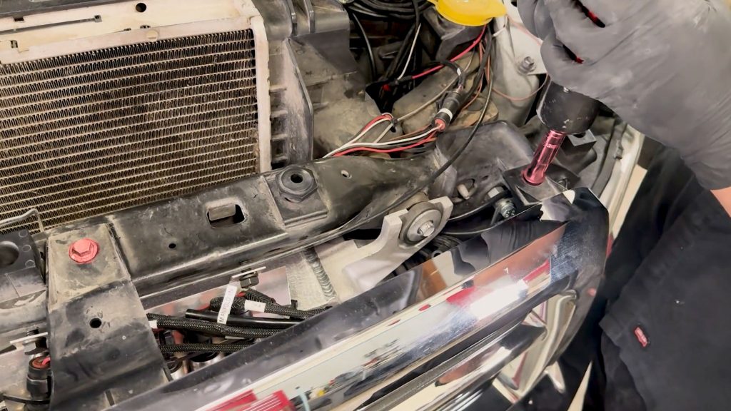
23. There are 4 bolts.
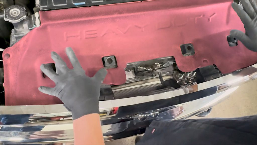
24. Reinstall the upper core support cover. Press the tabs to lock it in place
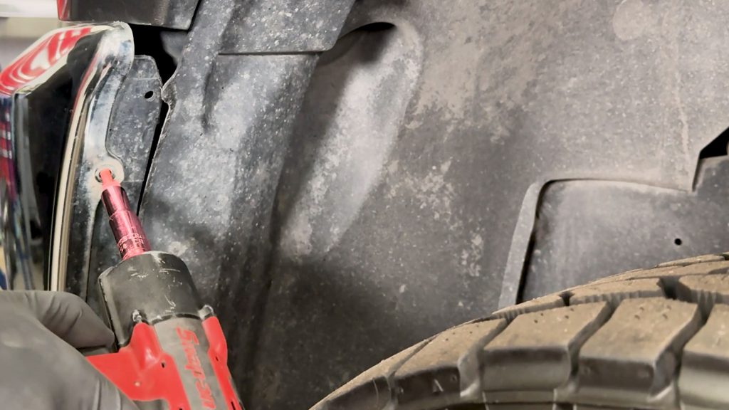
25. With a 10mm socket, re secure both sides of the lower bumper.
Section 3: Banks Boost Tubes Install
ATTENTION: Boost-Tube Clamps
Before starting the Boost Tube installation, it is important to understand proper clamp mounting to prevent the couplers from blowing off under load. Be sure the hose and clamps go on far enough to clear the bead on each end.
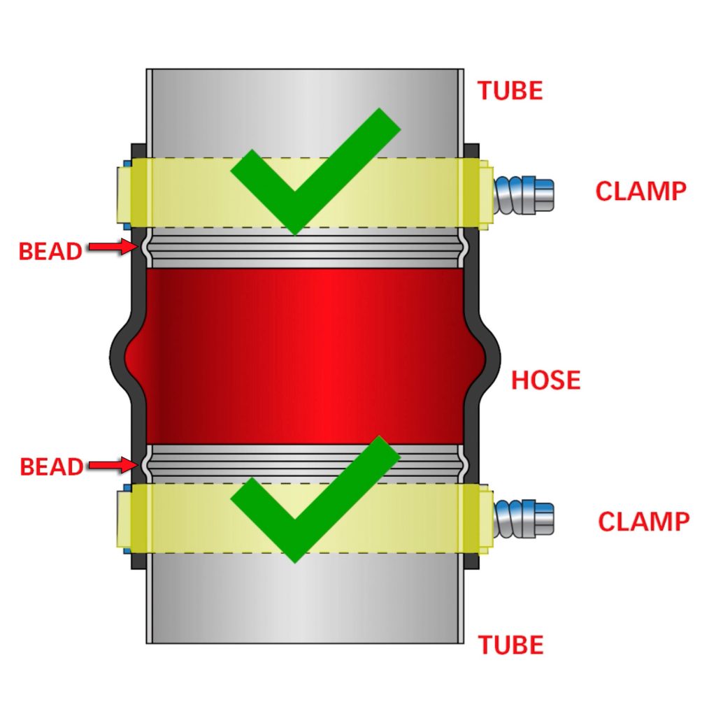
An improper installation, such as a clamp sitting directly on a bead or crossed diagonally, will result in a boost leak.
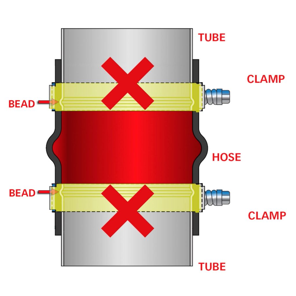
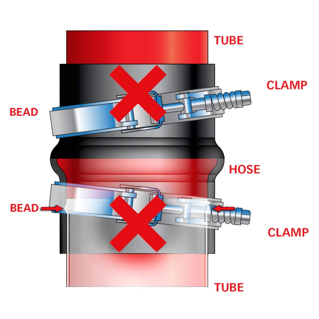
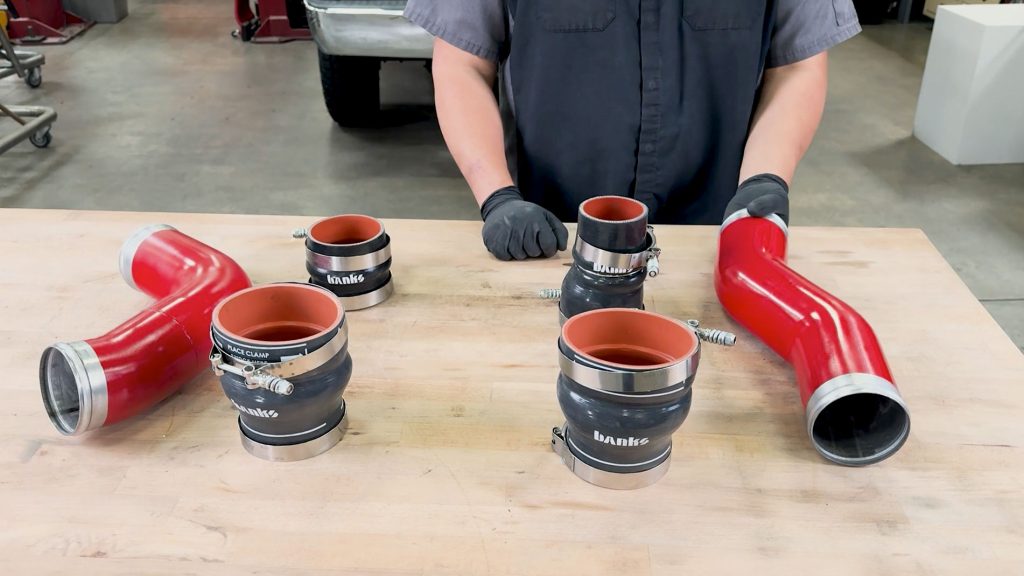
1. Grab the hot side Banks Boost Tube, Oval Hose, Offset Hose, and clamps for each.
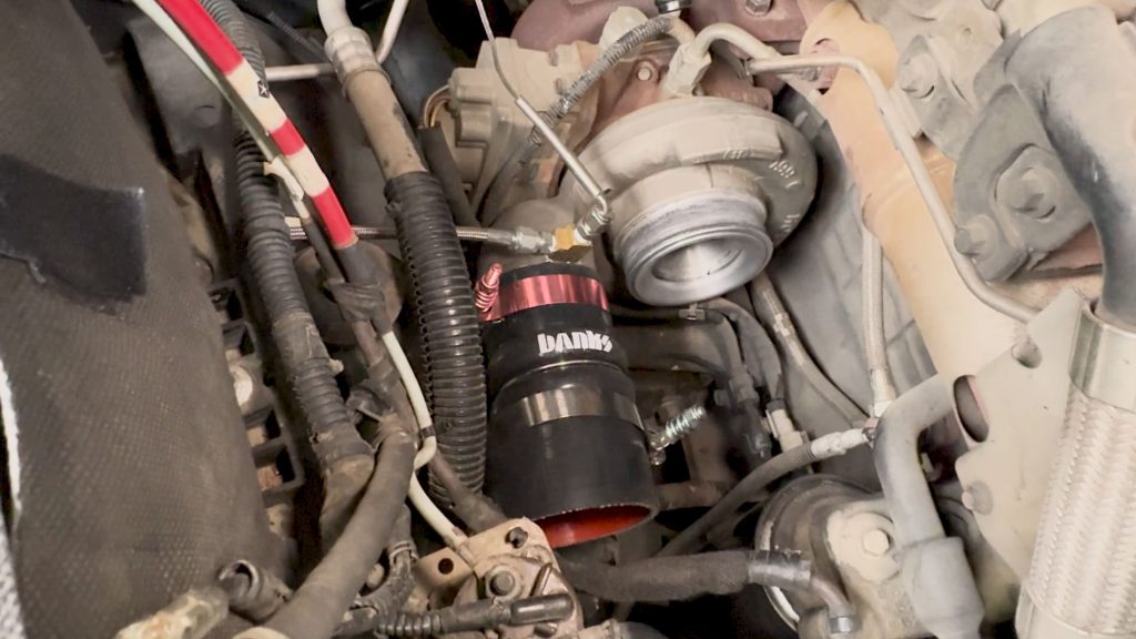
2. Slide the Offset Hose with clamps, onto the Turbo Compressor Outlet.
Note: the bulge of the hose should face outside towards fender.
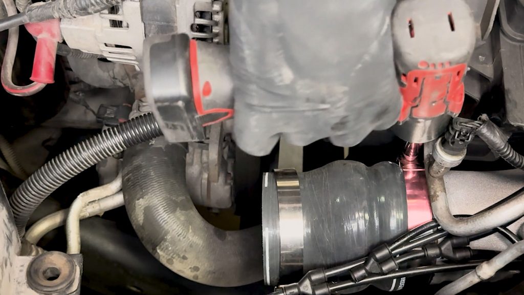
3. Do the same with the Oval Hose on the hot side of the Banks Charge Air Cooler. Be sure to slip the hose far enough onto the CAC and secure it with a 11mm socket.
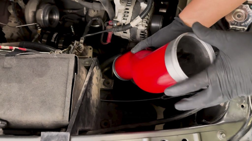
4. Carefully slide the Banks Hot Side Boost Tube down onto the couplers.
Be sure the bead of the boost tube is not resting underneath the clamp.
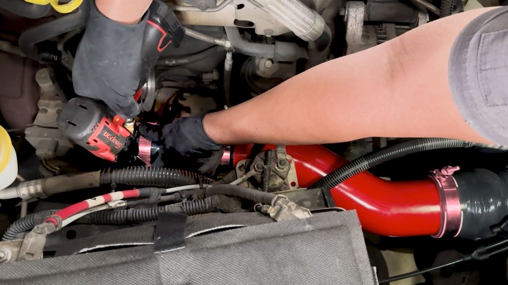
5. Slip the hose onto the boost tube with a flat head screwdriver. With a 11mm socket, secure the clamps.
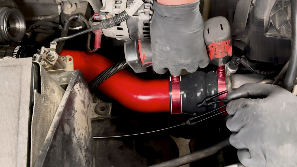
Be sure all clamps are straight, flat, and tightened down.
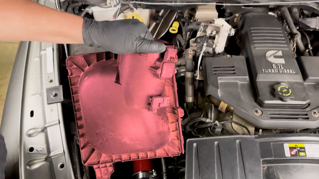
6. Reinstall the Air Box, making sure the grommet snaps back into place.
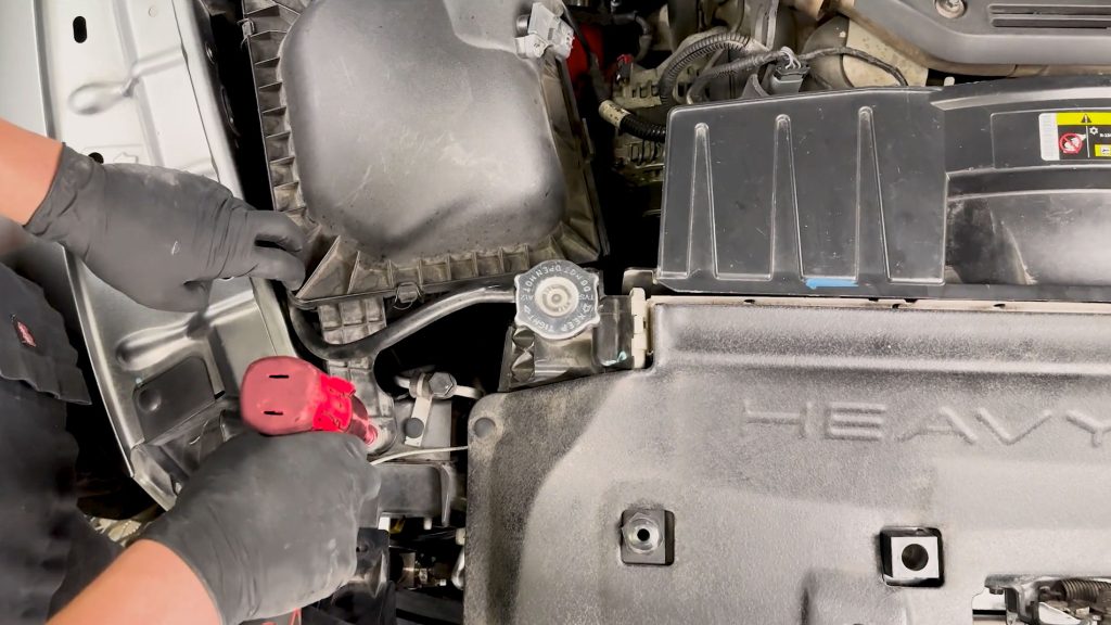
Secure the top bolt with a 10mm socket.
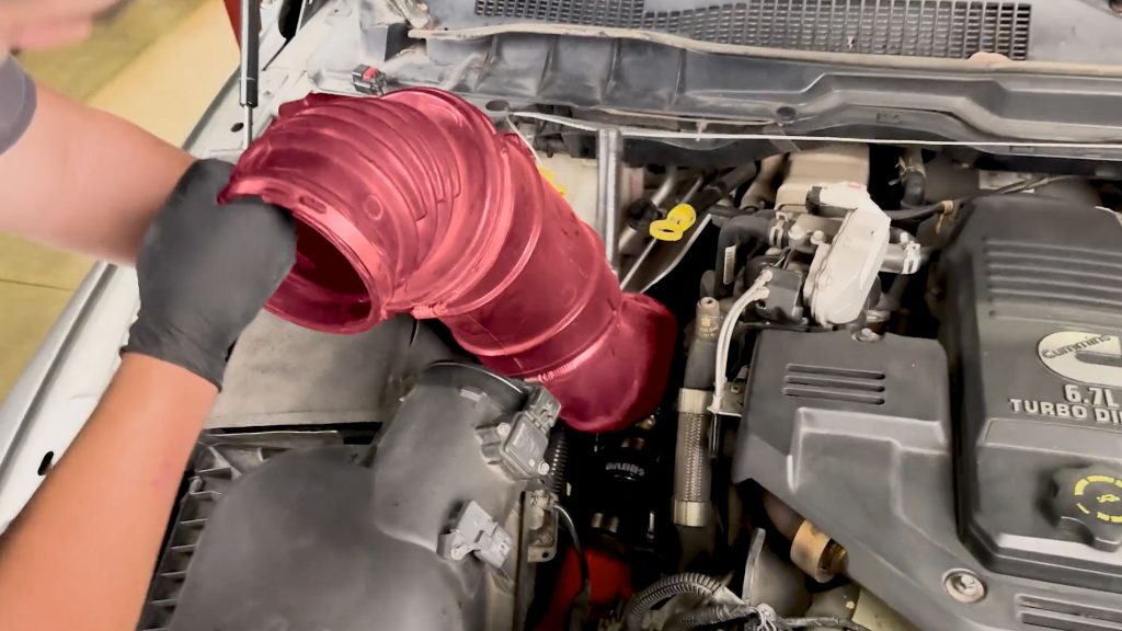
7. Reinstall the intake tube.
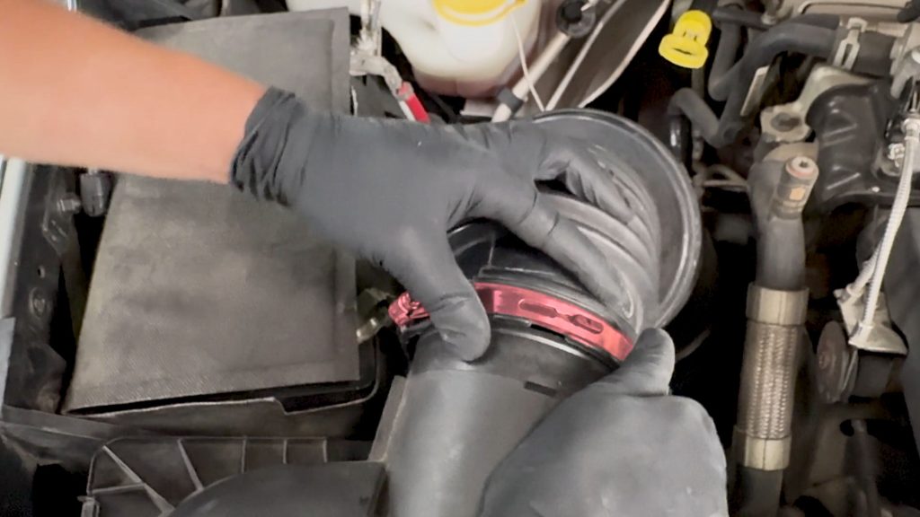
8. Secure the upper clamp with a 8mm Nut Driver or Flathead Screwdriver.
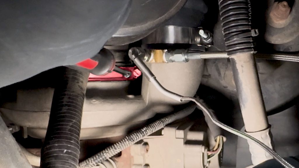
Do the same for the lower clamp on the Turbo Inlet.
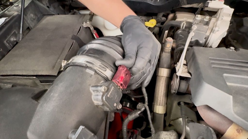
9. Reconnect the two sensors on the airbox.
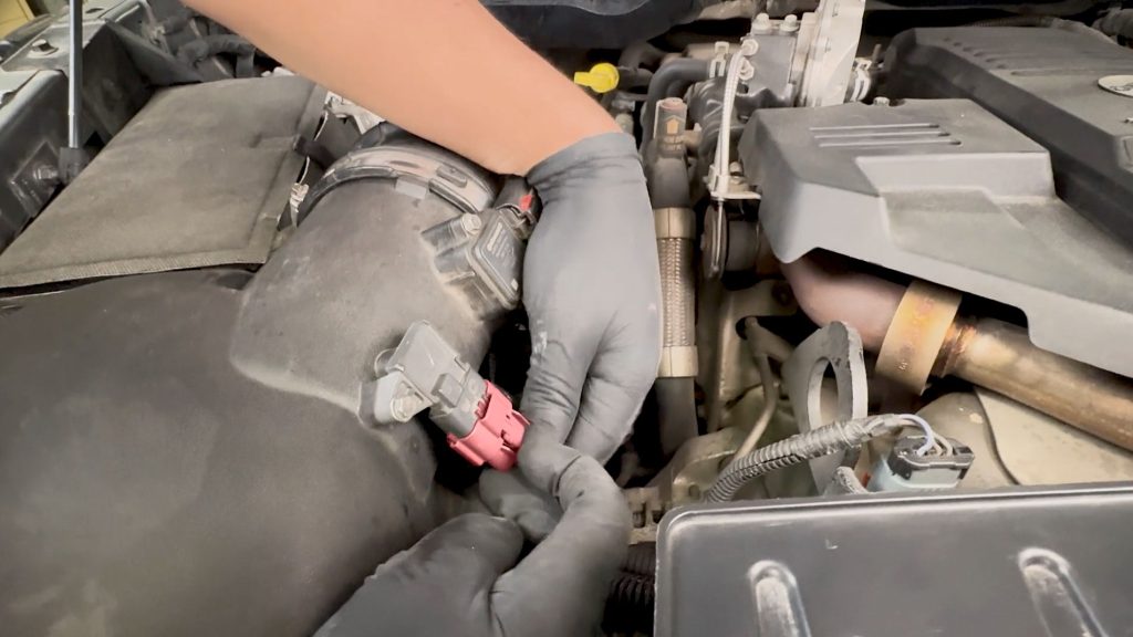
Be sure they snap back in with locking tabs in place.
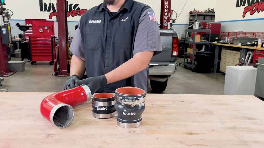
10. Grab the Banks Cold Side Boost Tube, Oval Hose, Hump Hose, and clamps.
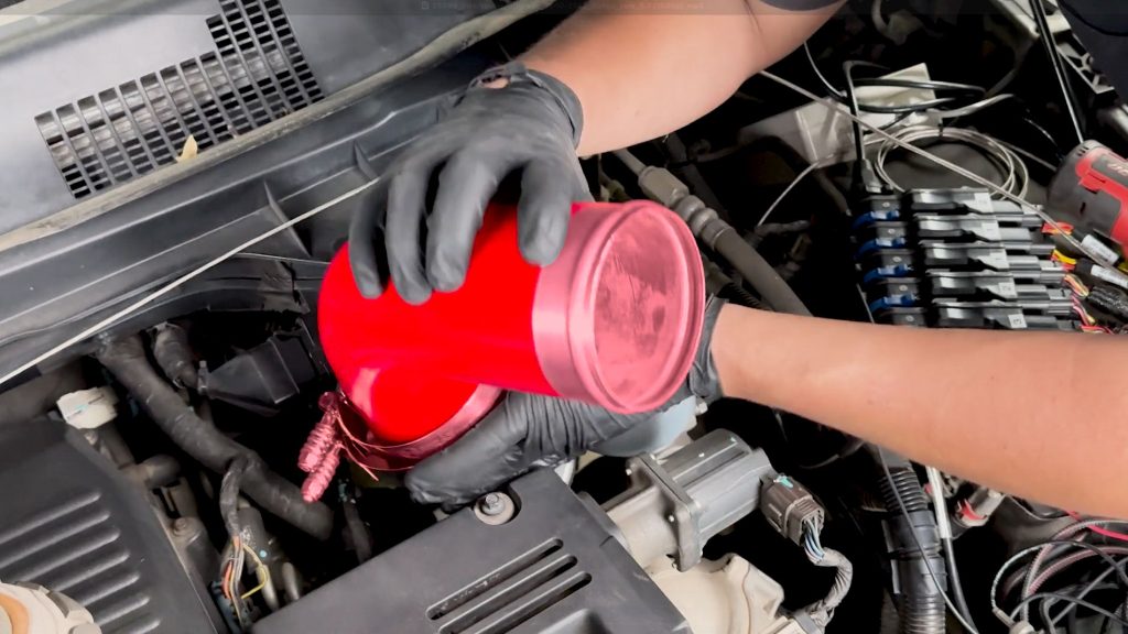
11. With the Oval Hose and clamps attached, lower the Banks Cold Side Boost Tube into place.
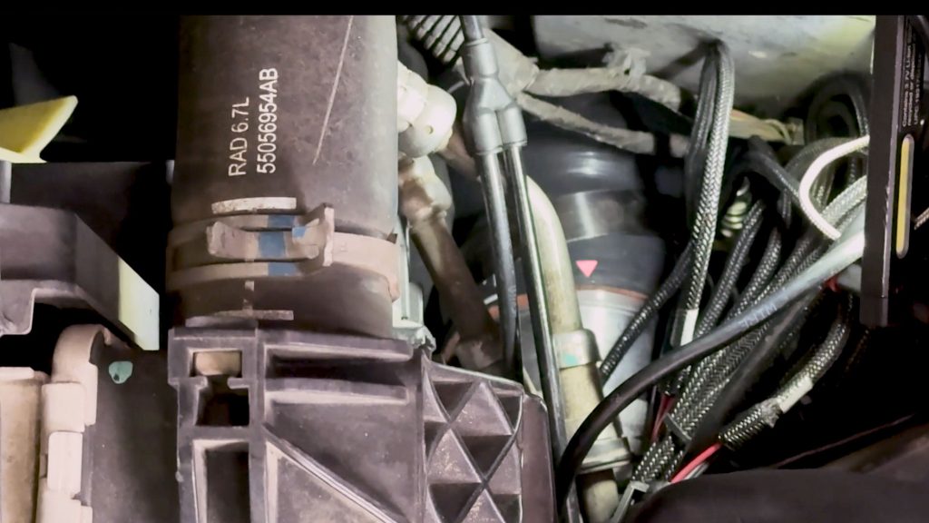
12. Line up the guide arrow, and slide the hoser all the way into place.
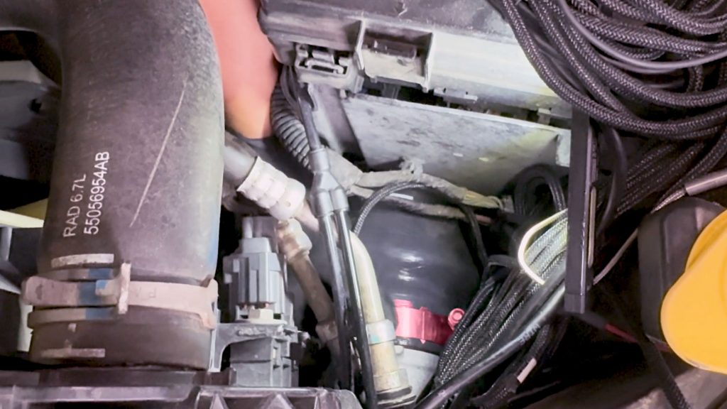
Be sure the clamp does not rest on top of the bead of the CAC.
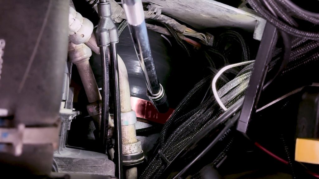
13. With a 11mm socket and extension, tighten the clamp.
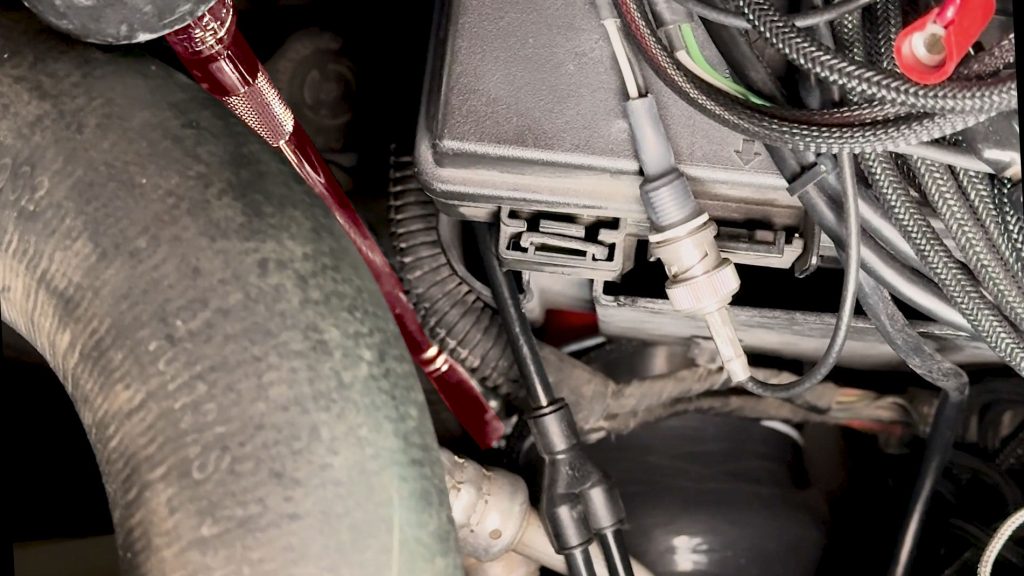
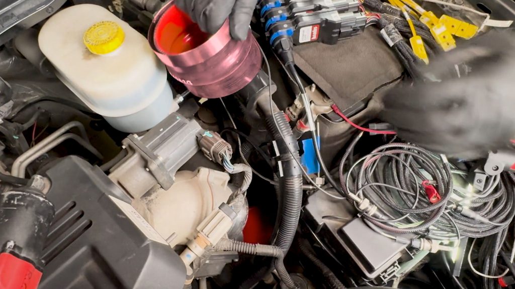
14. Grab the upper Hump Hose and clamps, and slip them over the Banks Cold Side Boost Tube and Intake Horn.
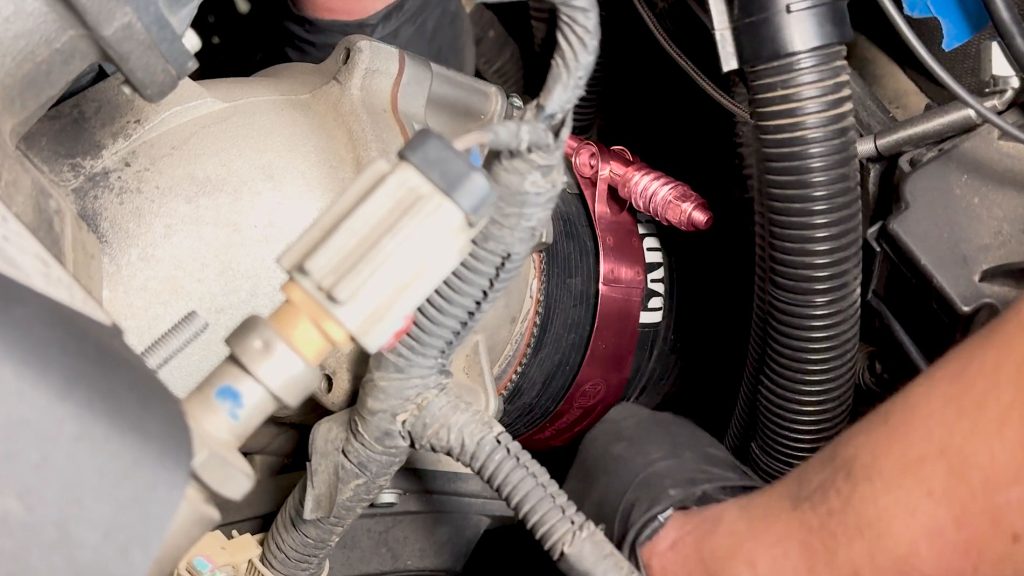
15. Be sure to slide the hose far enough on the intake horn to provide space for the clamp to clear the bead.
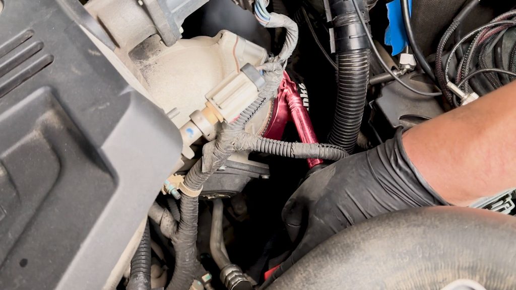
16. With a 11mm socket, secure the upper clamp.
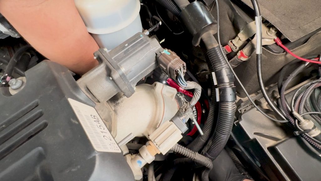
Do the same for the lower clamp.

