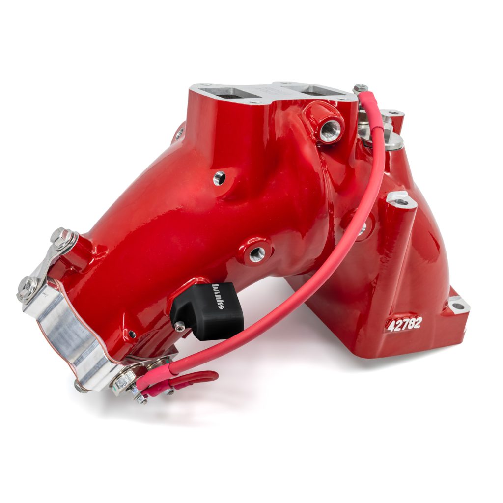
97737 Dual-Heat Monster-Ram Intake System w/fuel line-2019-24 RAM 6.7L Cummins
INSTALL INSTRUCTIONS
Part #s
42799, 42799-PC, 42799-B
Banks Ram-Air® Intake System 2019-2024 RAM 2500/3500 6.7L Cummins
Please read through the following instructions thoroughly before starting your installation. If you have any questions please visit our Support Page.

Dual Heat Capable Monster-Ram w/Intake Plate Install Video
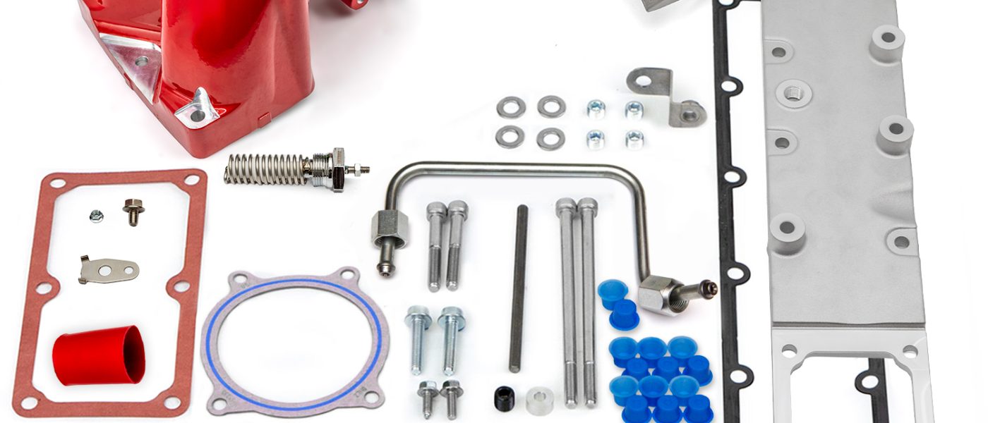
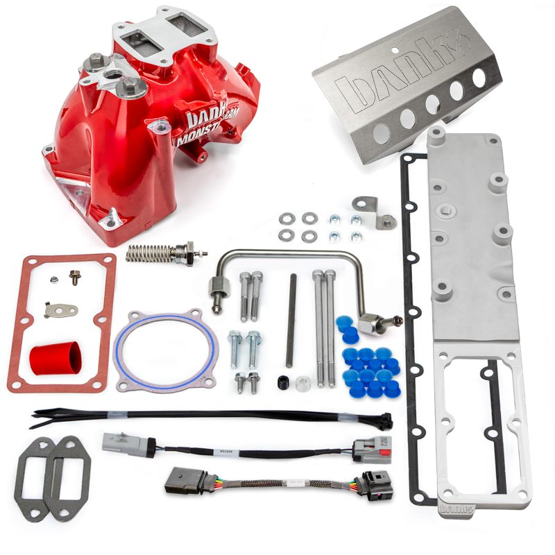
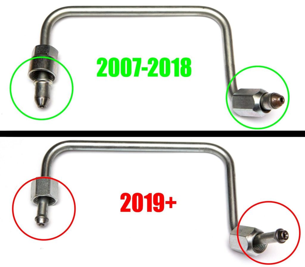
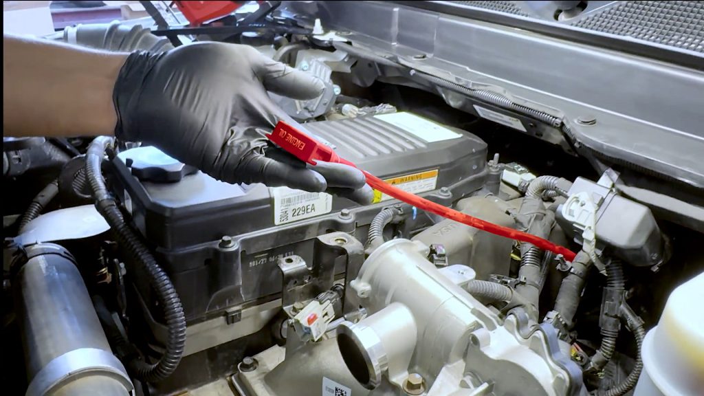
In an effort to make sure you have the right kit for your model year. Visually check which fuel line is included in your kit before starting installation.
Important Notes:
IMPORTANT!
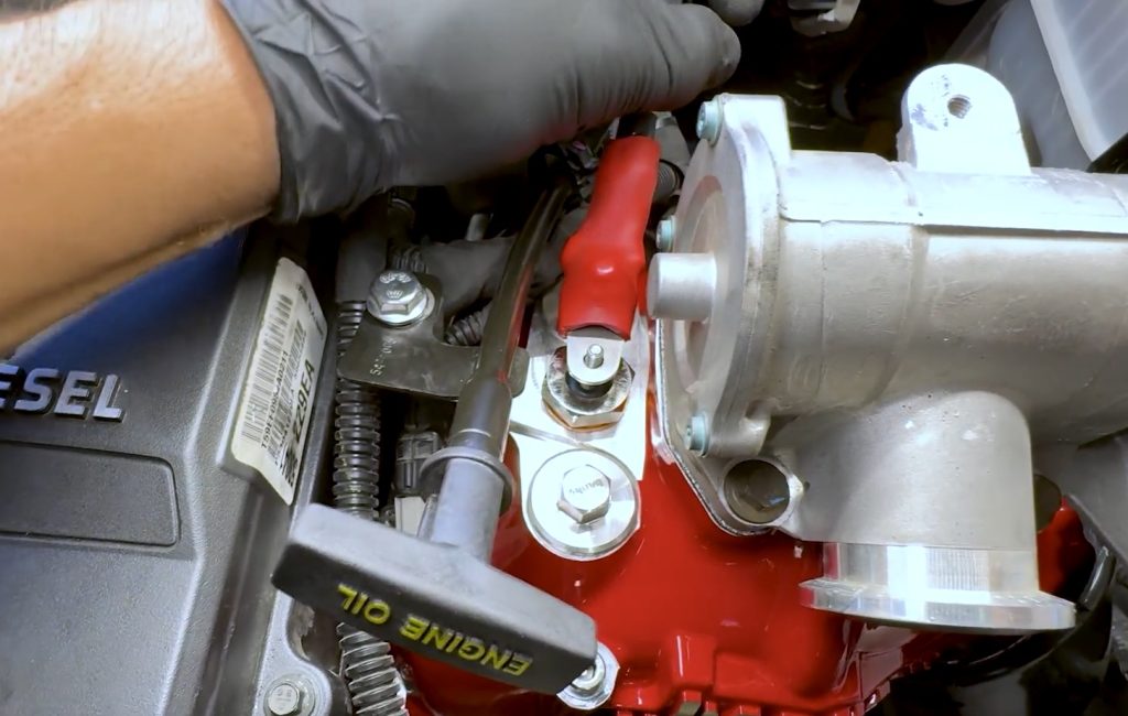
Coil heater preparation: The lower nut must remain 1/8″ above the coil heater body (about 2 threads visible).
Take care when installing OEM heater wire ring terminal, it must be sandwiched between the upper and lower nut. If the lower nut is too low, the ring terminal could contact the body of the coil and will short out.
When tightening the nut, it is very important to use a 10mm wrench or socket on the top nut and an 8mm open-end wrench on the bottom nut to prevent the threaded post from rotating. If the threaded post rotates, it can break the ceramic insulation it’s surrounded by.
If the OEM heater wire touches other metal components, an open short will occur.
Copper washer: All kits now ship with a copper crush washer. Place this washer between the coil heater before screwing it into the Monster-Ram.
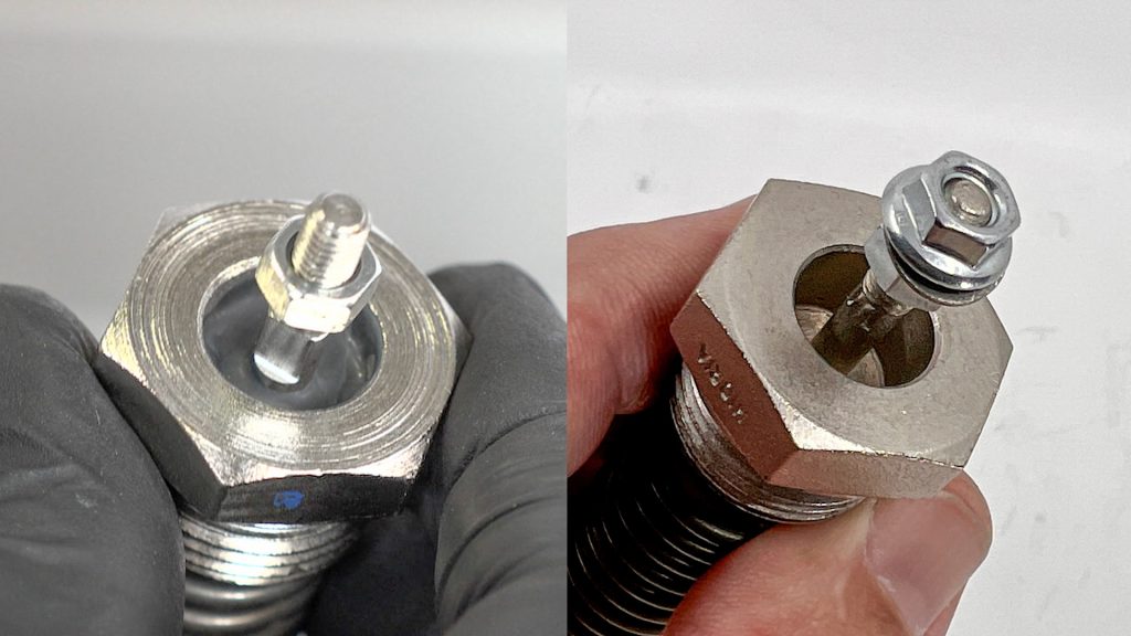
Coil-Heater Variants
Your kit may include one of two different style heater coils. One with a visible ceramic insulator, or one that isn’t visible. Both offer the same level of heating performance.
Installing a Dual Heater Upgrade?
See our Dual Heater and Billet Heater Upgrade supplement for important wiring information and diagrams.
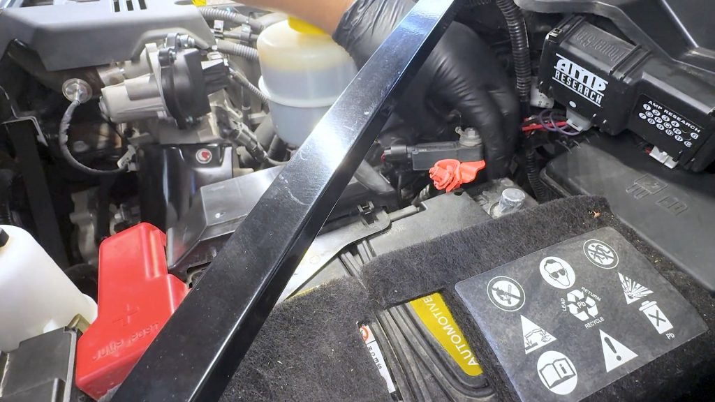
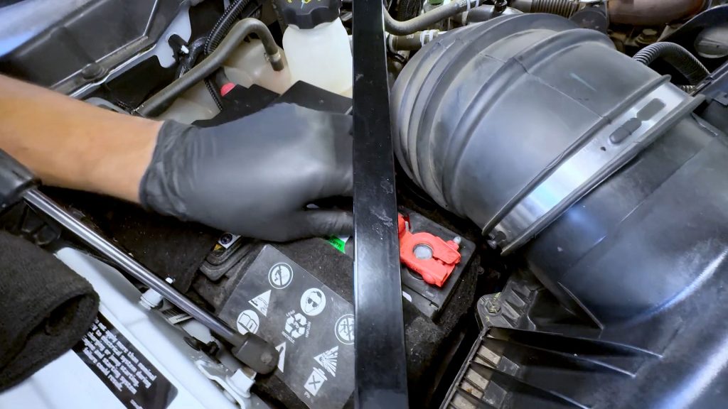
1. Disconnect Batteries
1. Place a rag around each of the negative battery cable ends; this will prevent them from touching the battery again and arcing during the install as you work.
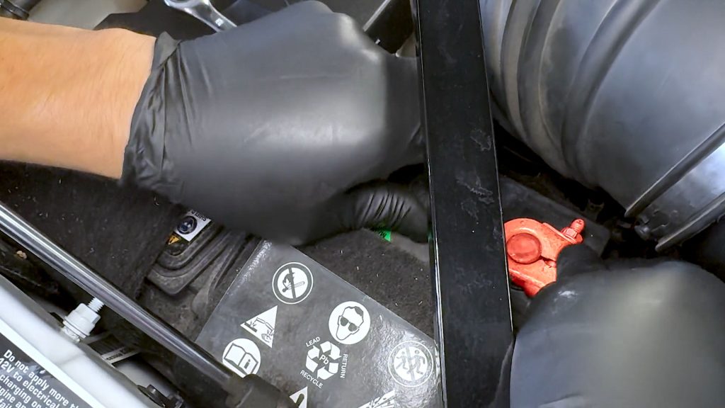
2. There is one on each side of the engine bay.
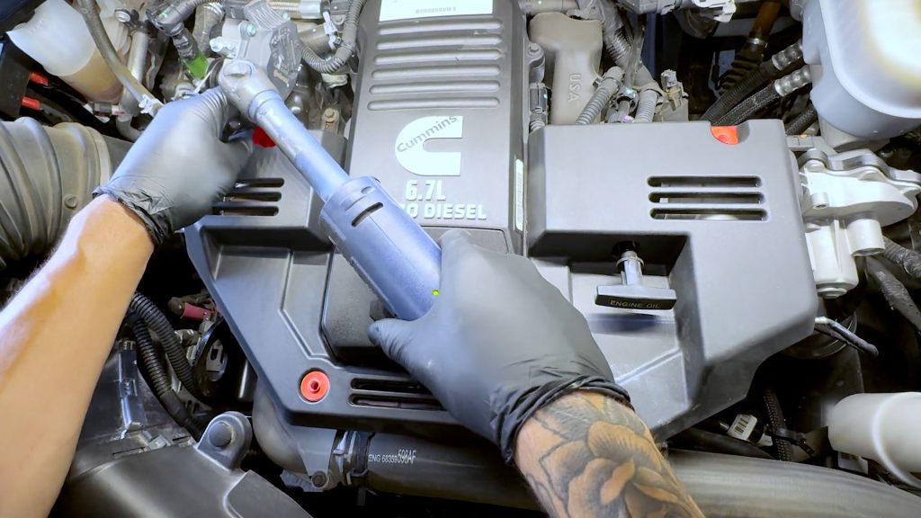
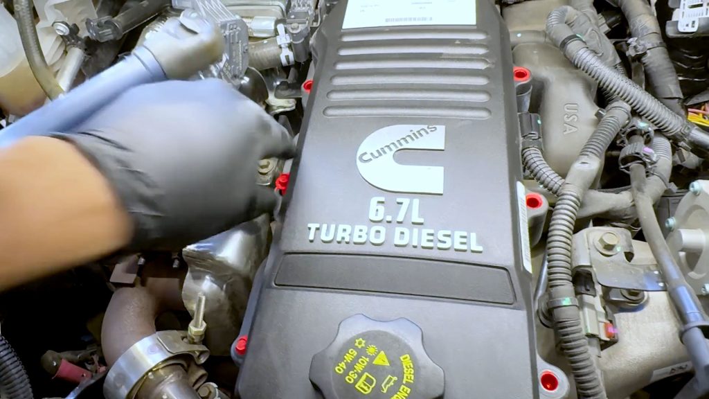
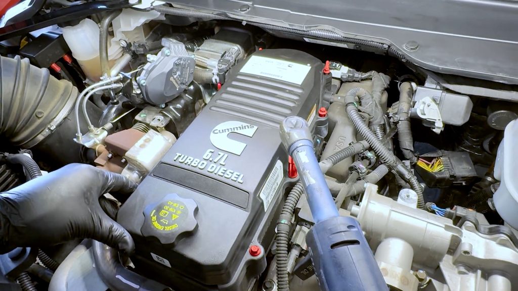
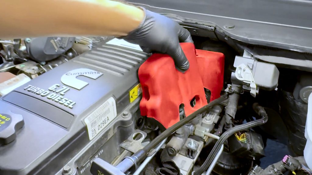
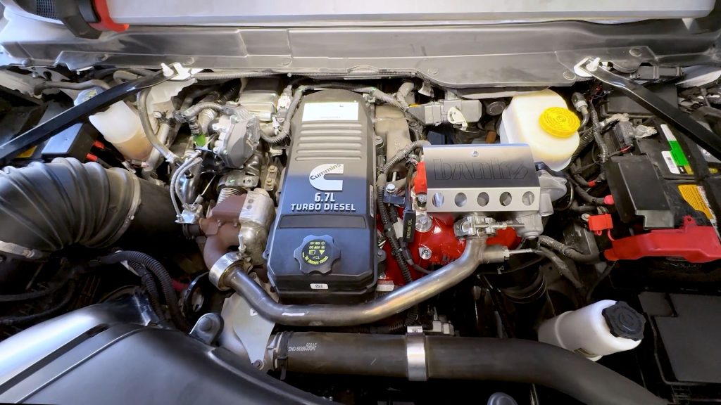
2. Remove Engine Cover
1. Use an 8mm deep socket to remove the four bolts holding the cover down.
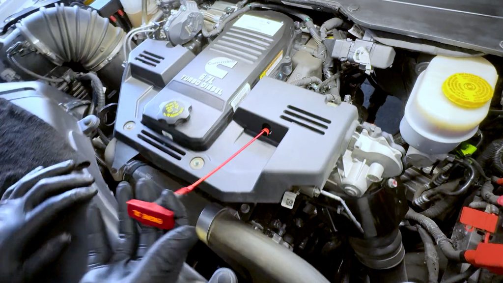
2. The dipstick needs to be removed for the cover to come off.
3. Don’t forget to replace it after the removal of the engine cover.
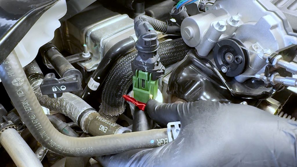
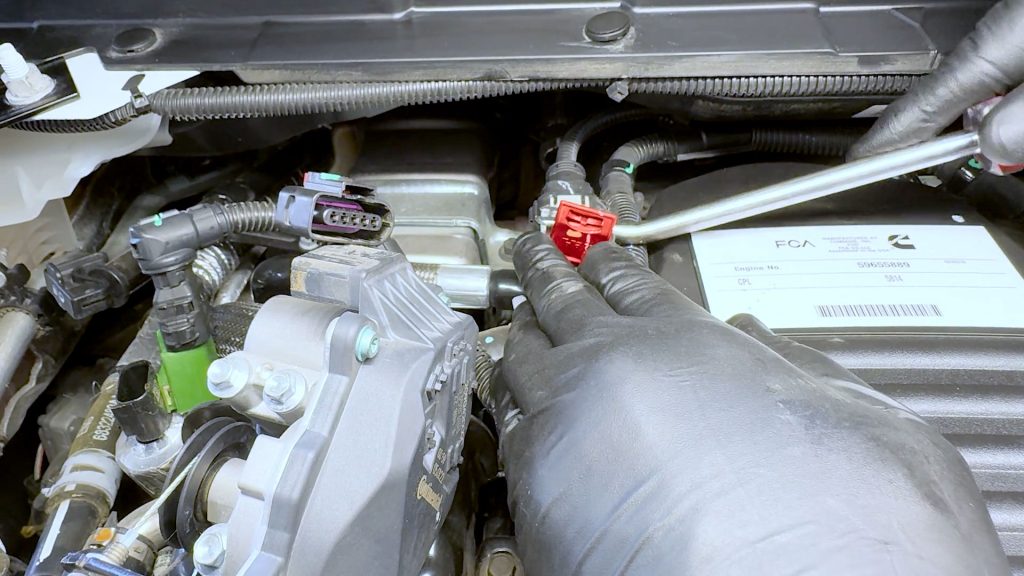
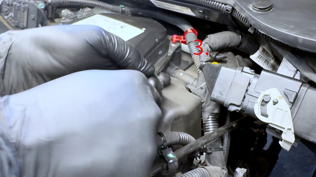
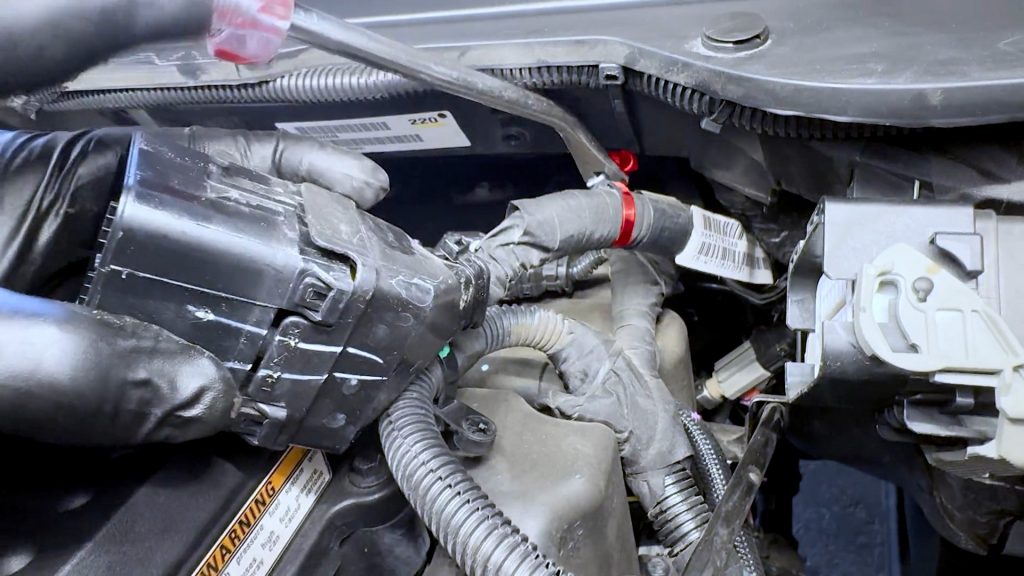
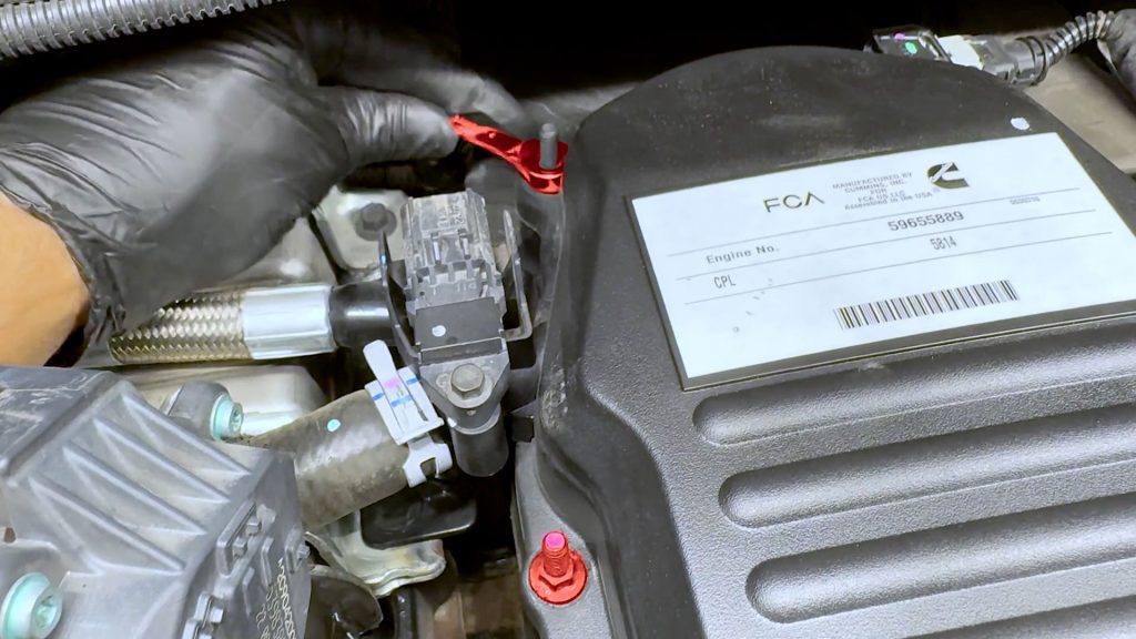
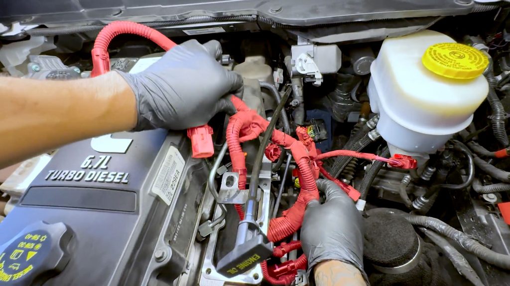
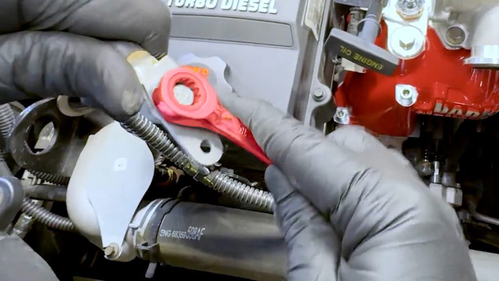
3. Free The Engine Harness
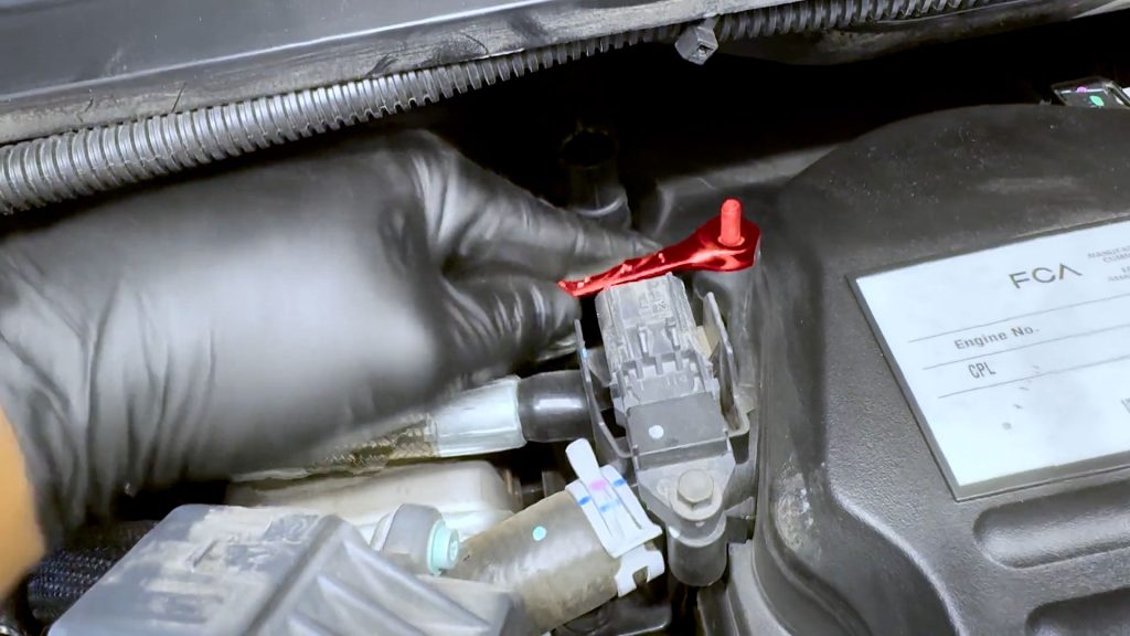
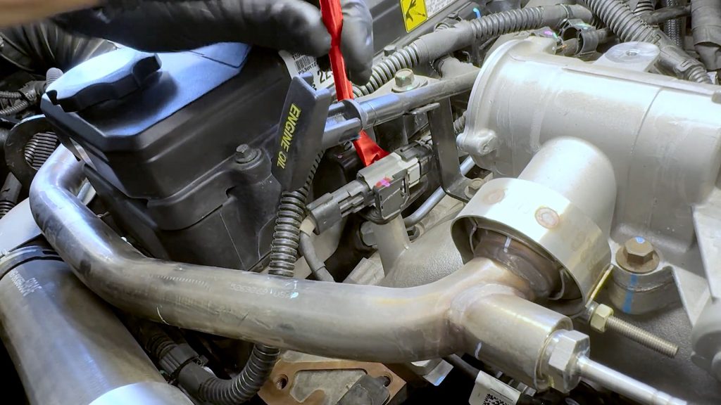
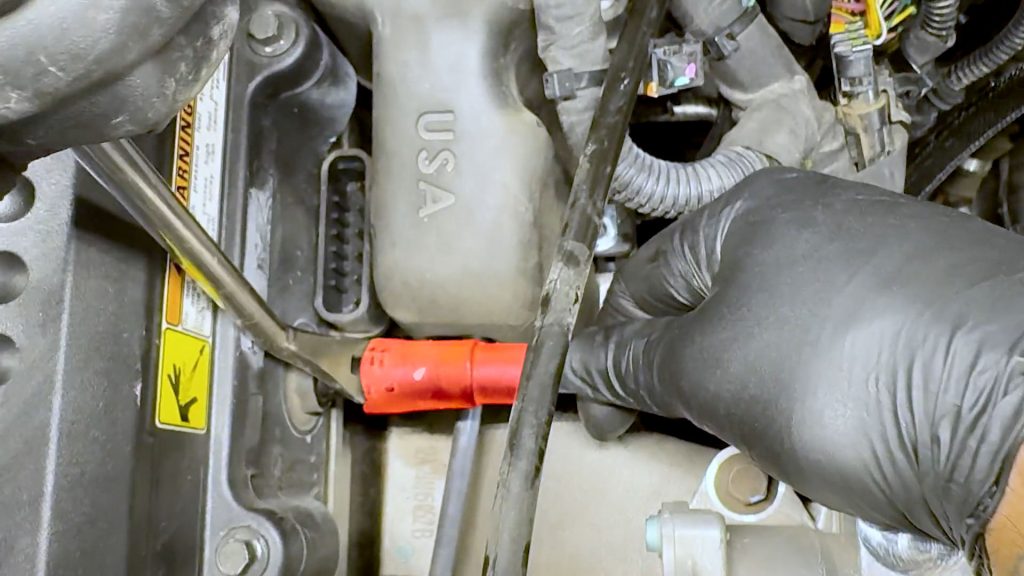
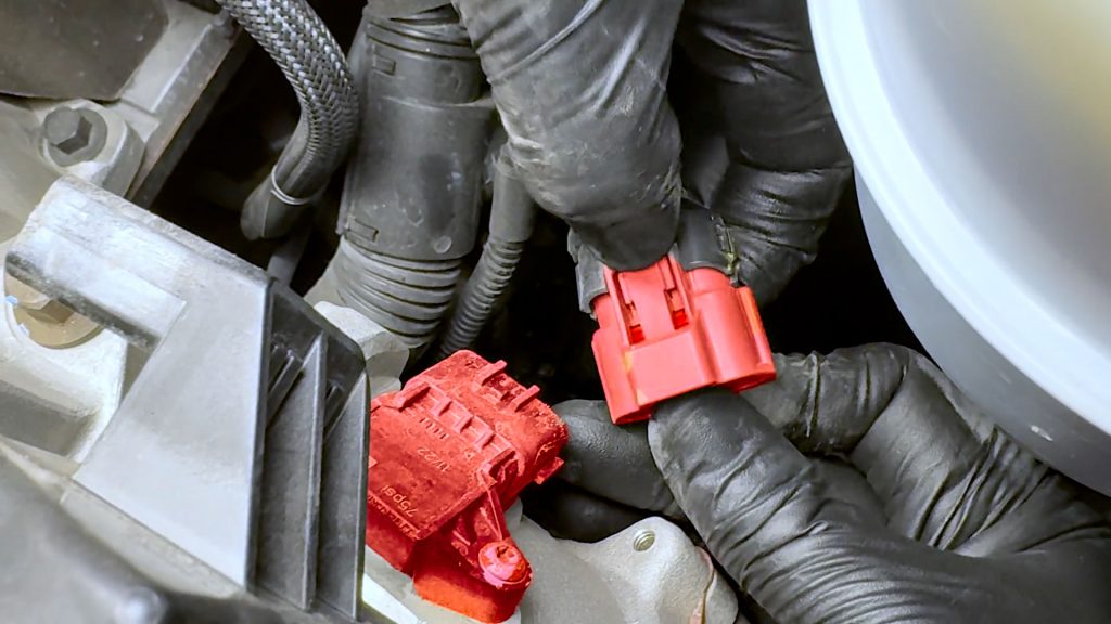
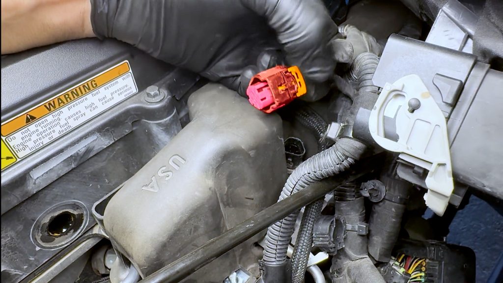
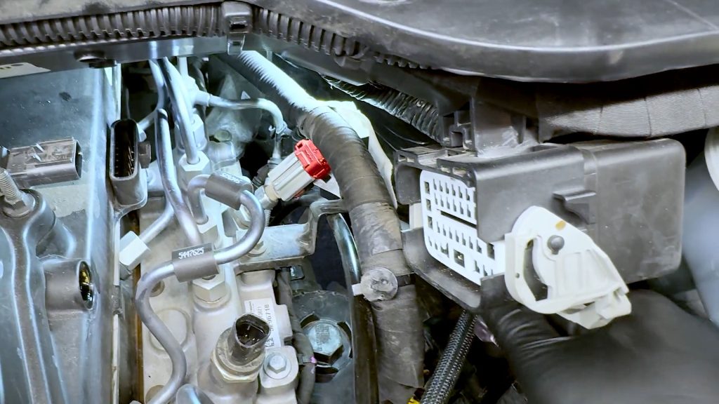
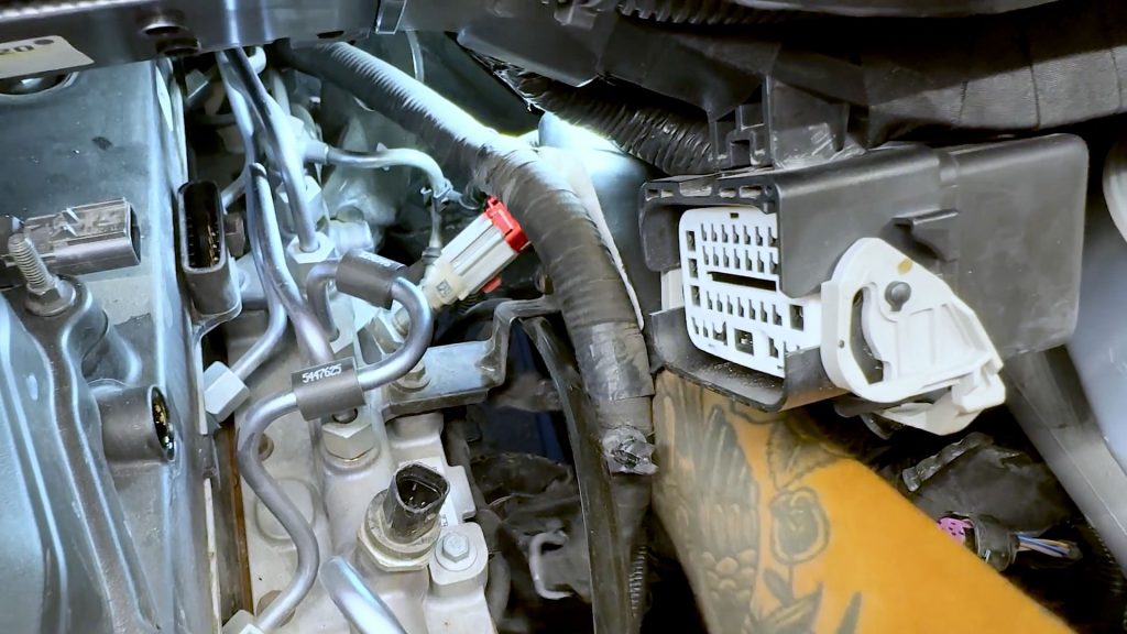
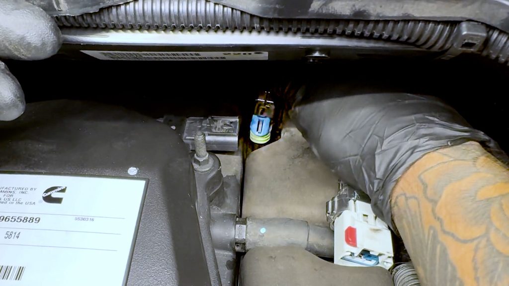
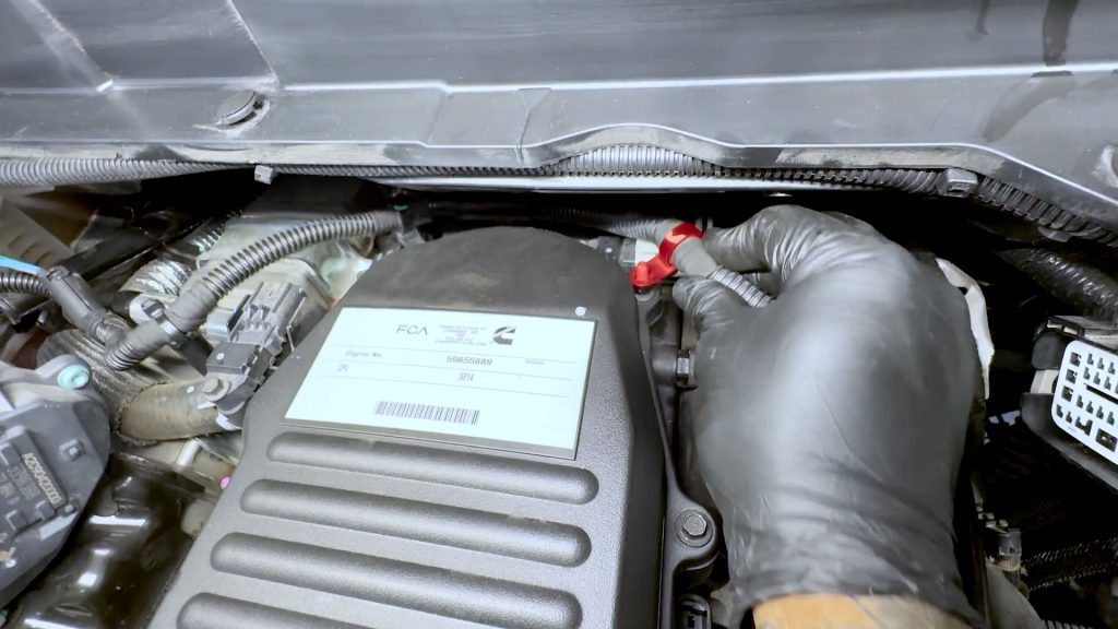
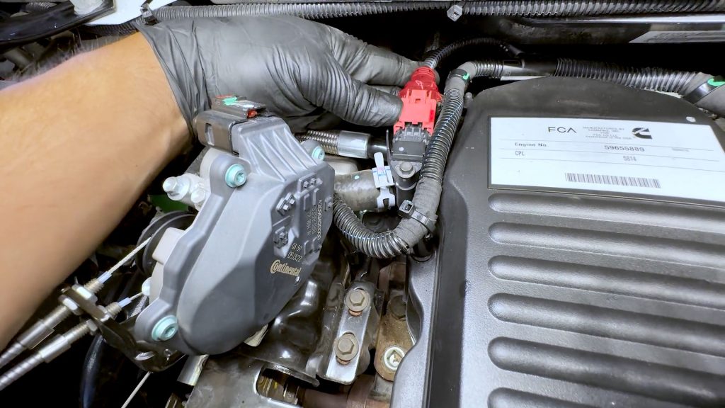
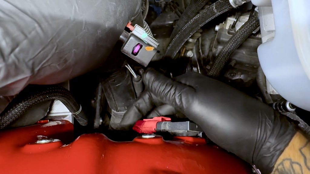
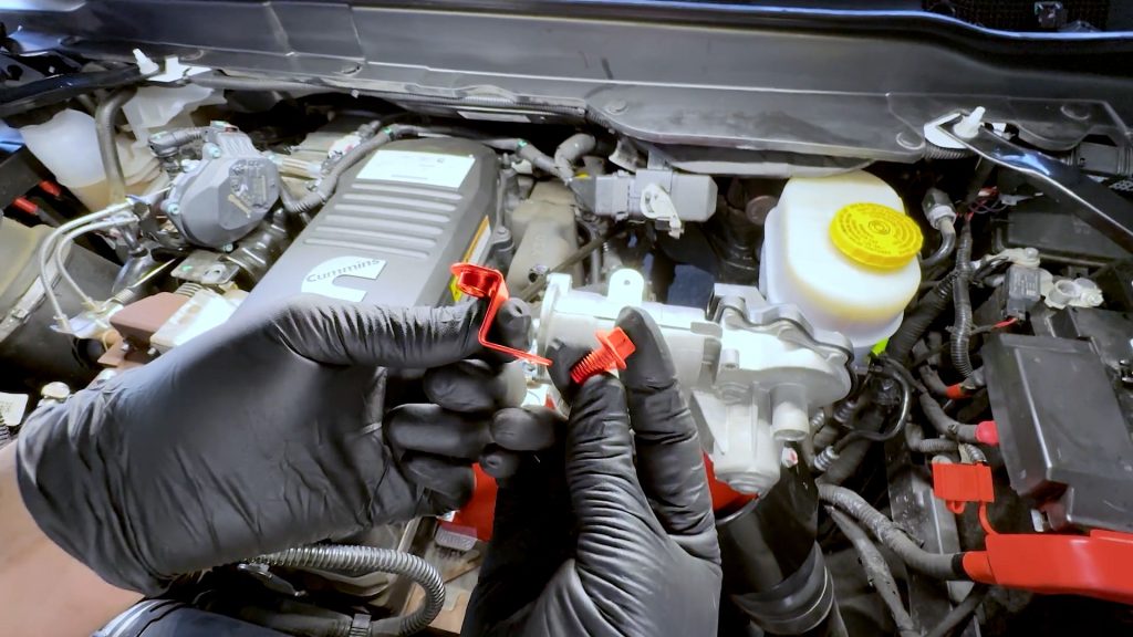
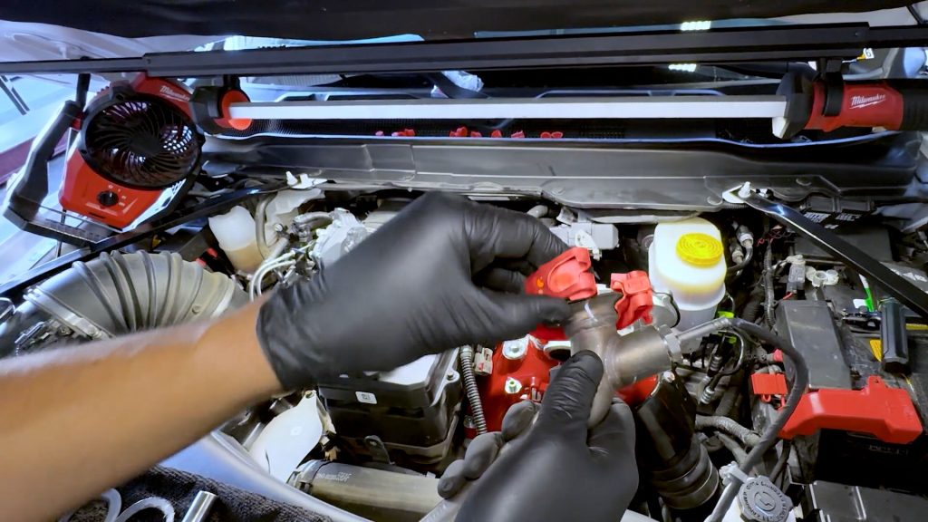
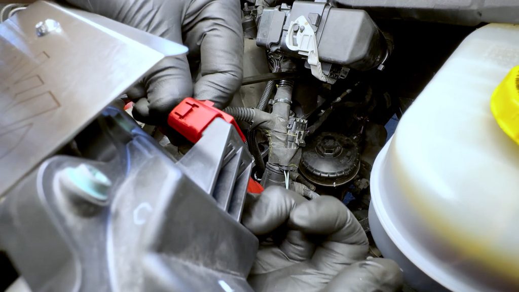
1. On the passenger side of the engine, locate the green plug near the EGR cooler.
Pop off the black plastic cover to expose the locking tab.
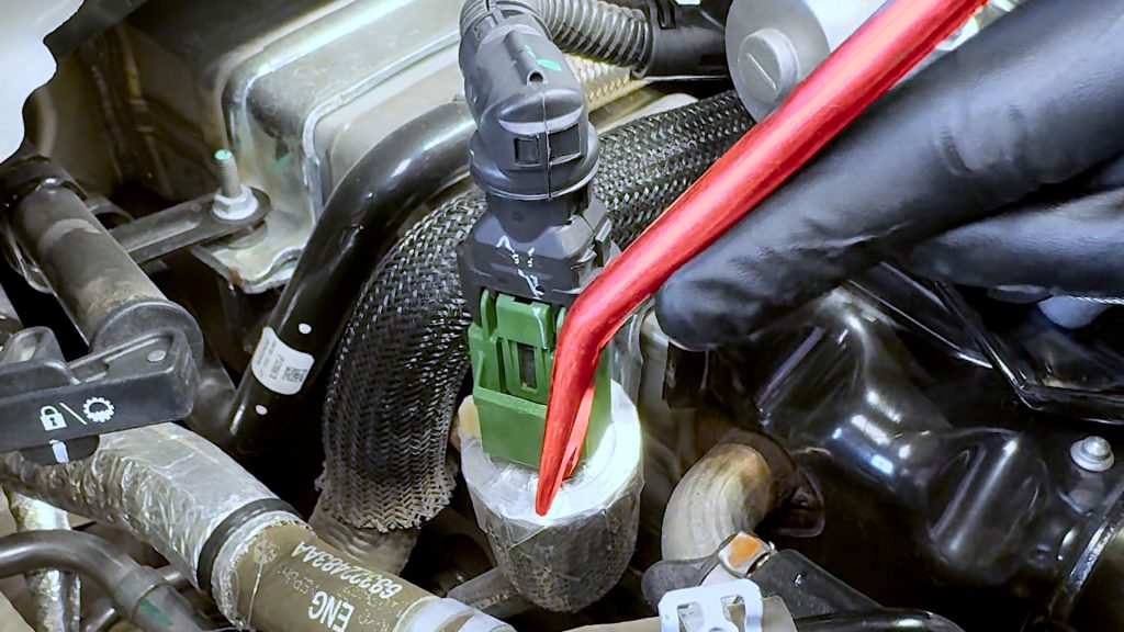
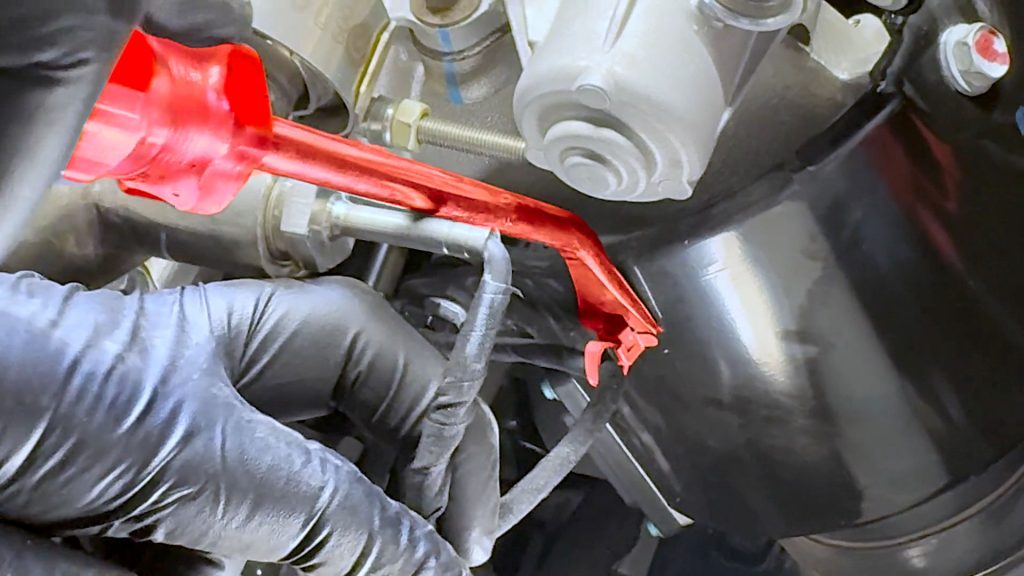
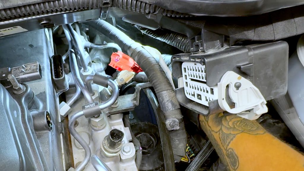
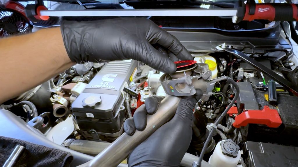
2. With a flat blade screwdriver, slide the exposed red locking tab over.
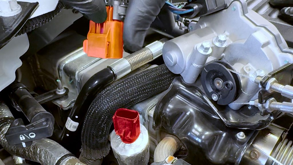
3. Then unplug the sensor.
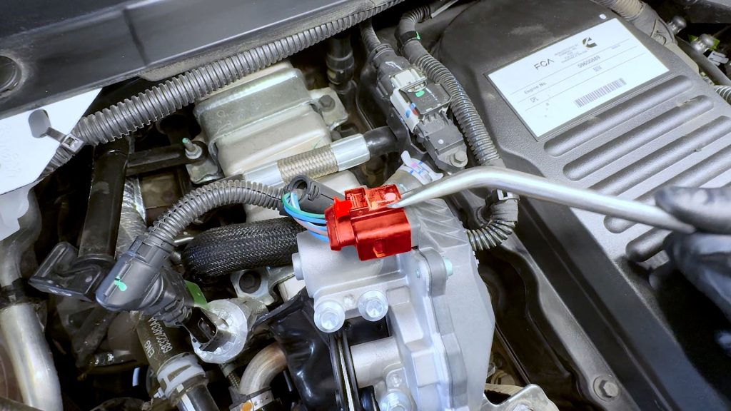
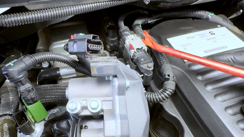
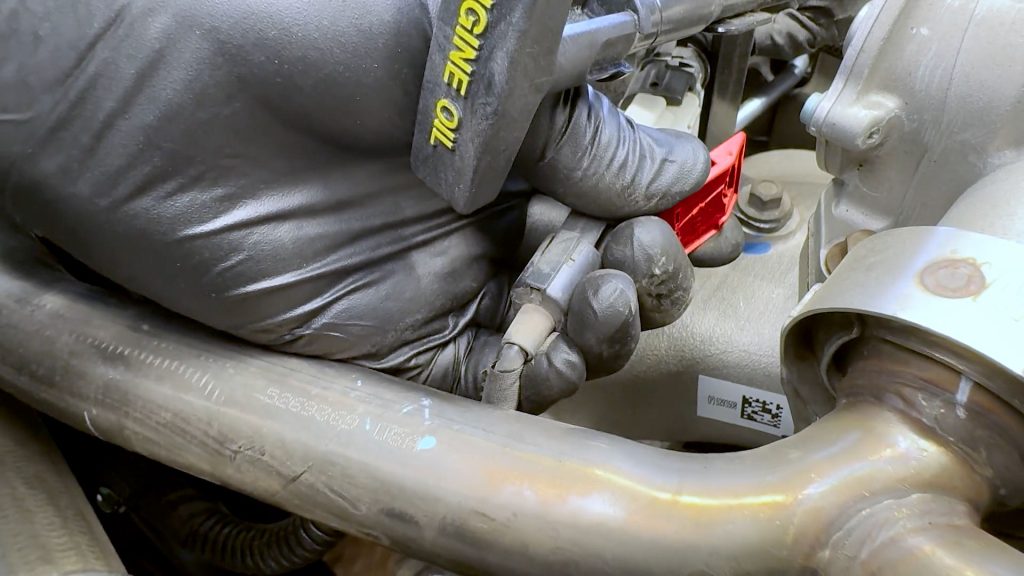
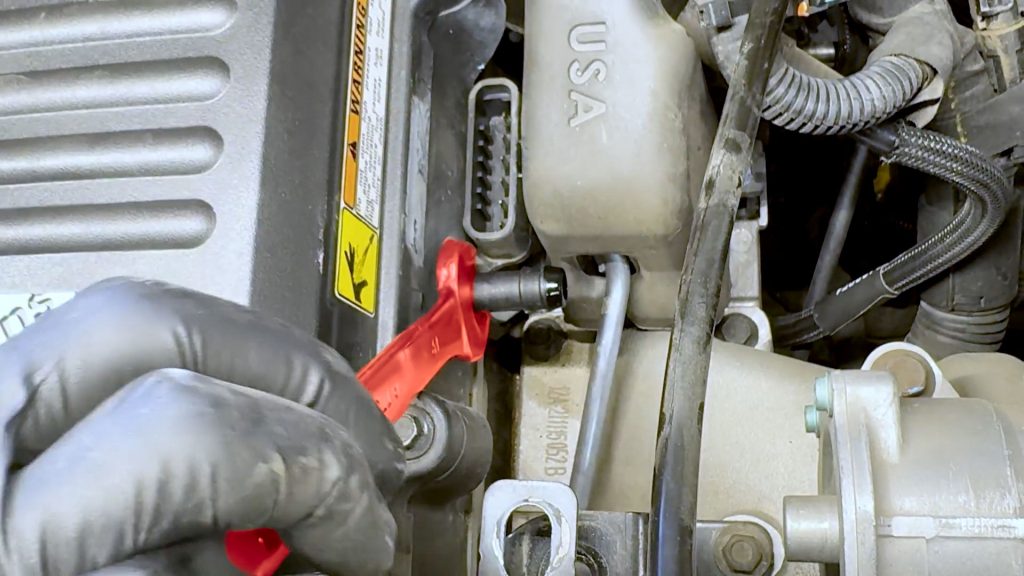
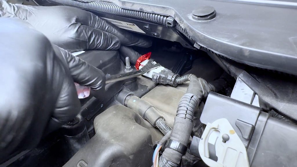
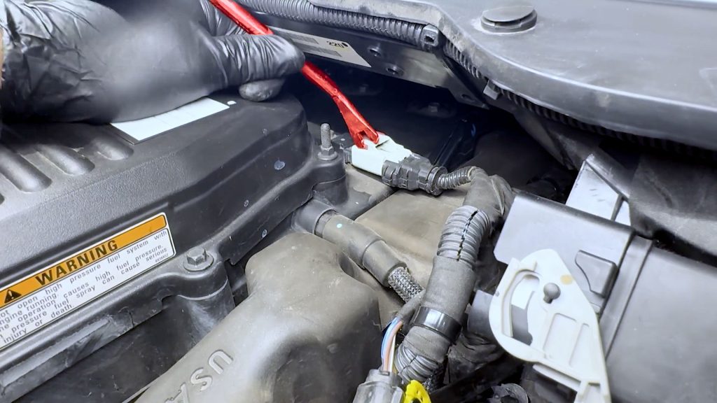
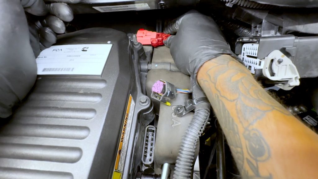
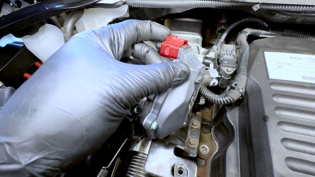
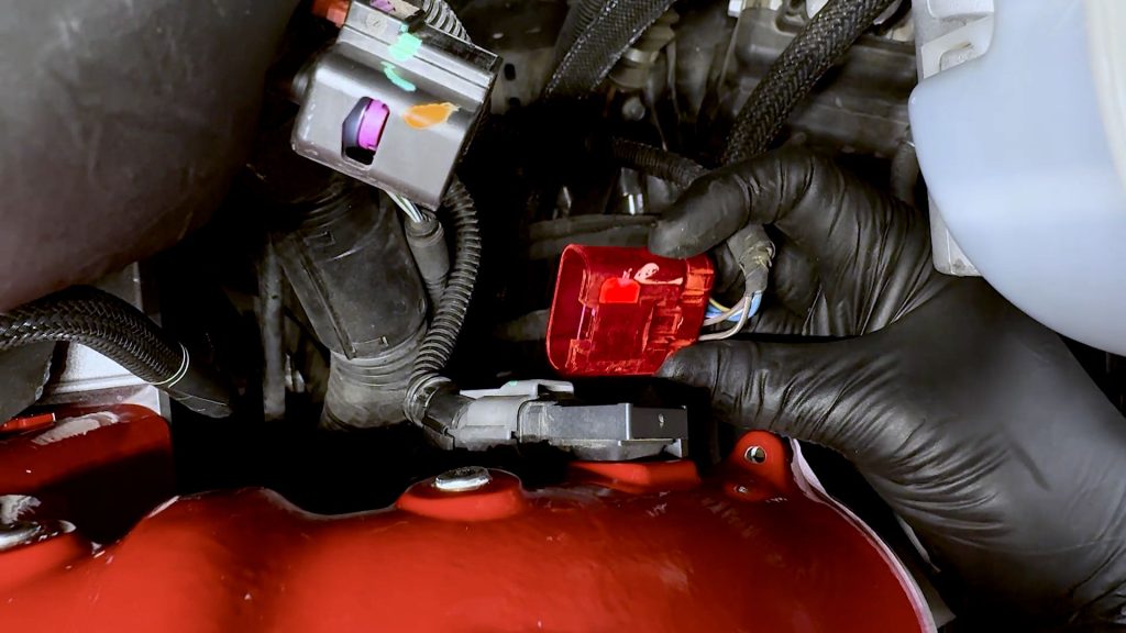
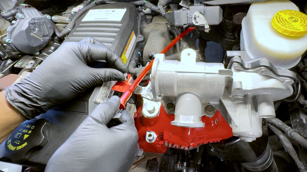
4. Continue with the sensor to the right on the EGR actuator. Use a flat-blade screwdriver to slide the red locking tab back.
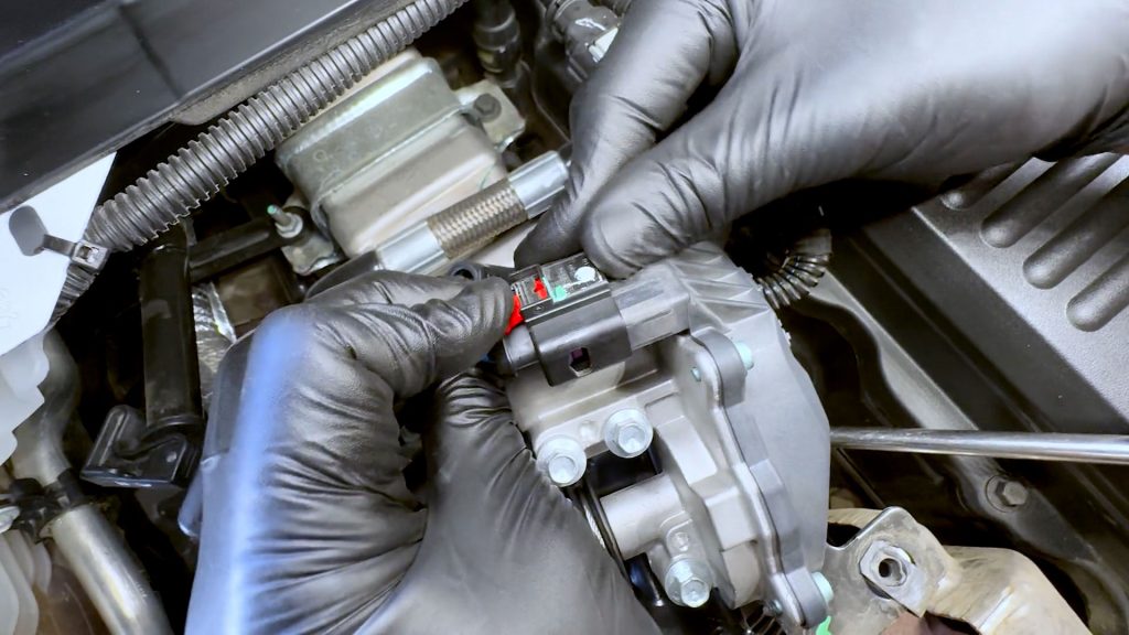
5. Depress the tab to free and unplug the it.
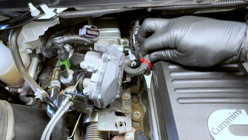
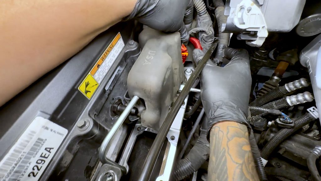
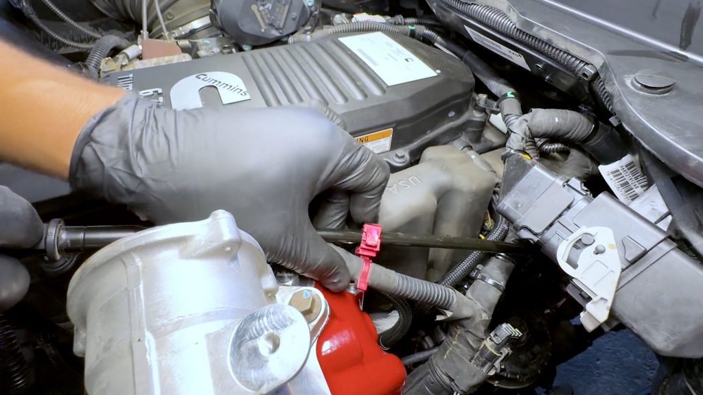
6. Continuing down the harness, with a flat blade screwdriver, free the wire harness cable tie from the first stud.
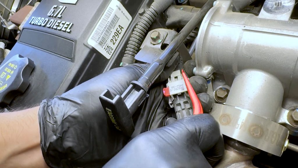
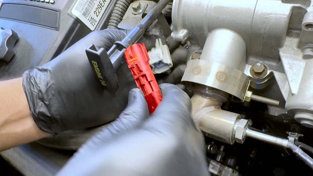
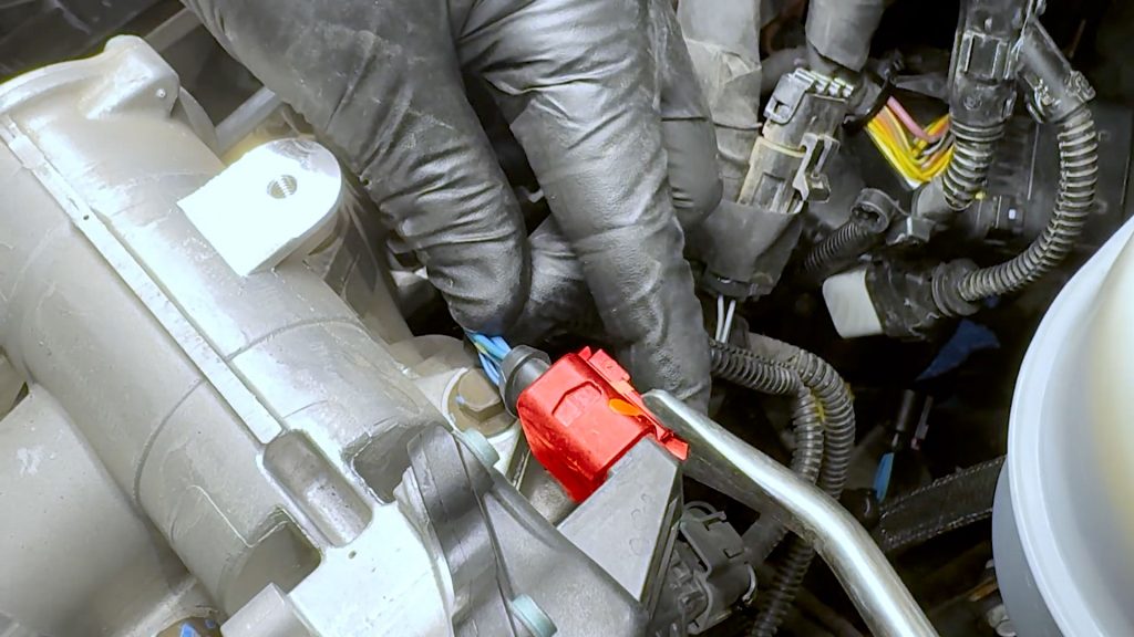
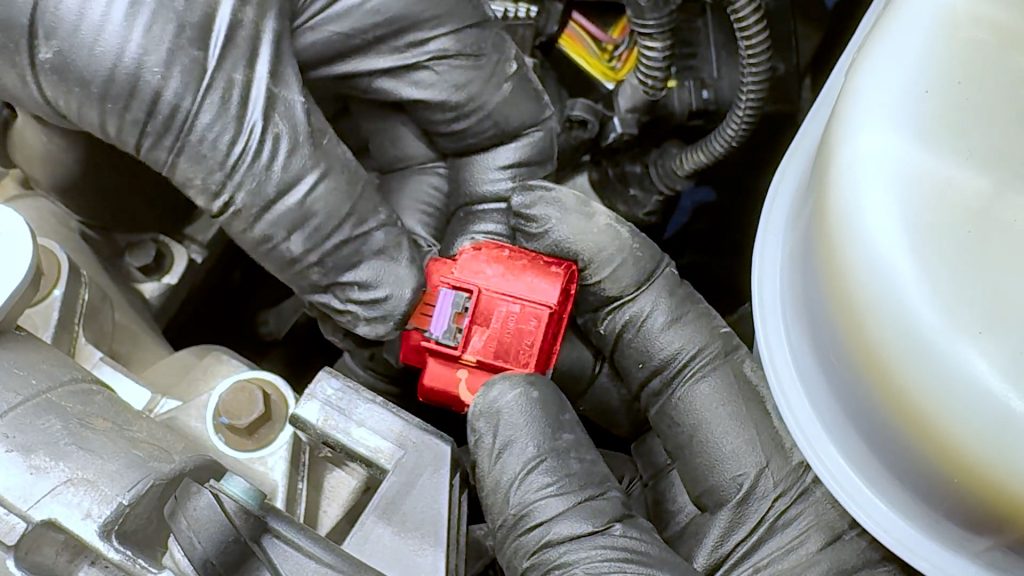
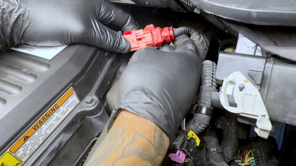
7. Pop the black cover off to expose the sensors’ locking tab.
8. With a flat-blade screwdriver, slide the red locking tab over.
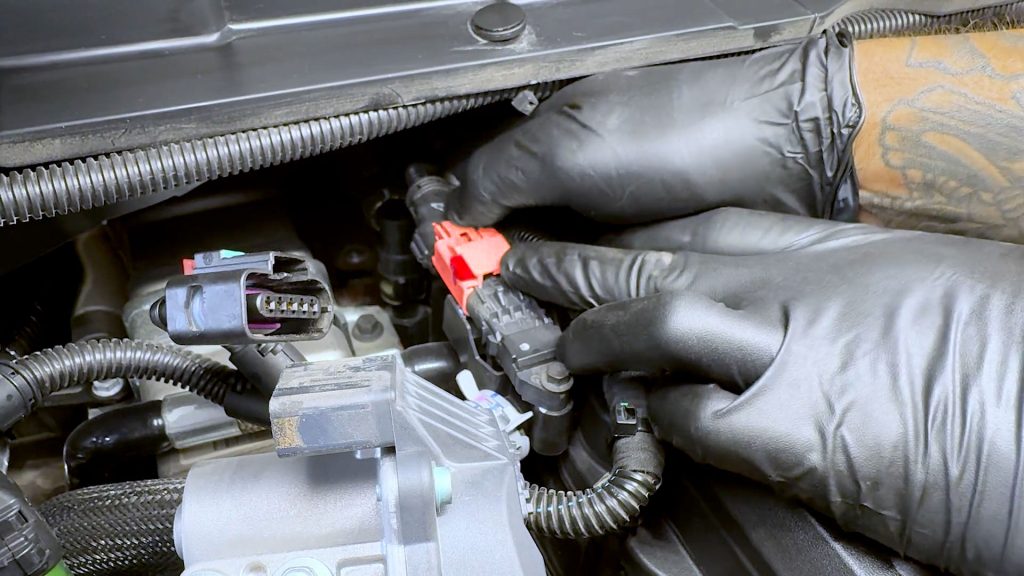
9. Depress the end of the plug and unplug it from the sensor.
10. Continue down the wire harness and free the second cable tie from its stud.
11. Continue down the wire harness and free the third cable tie from its stud.
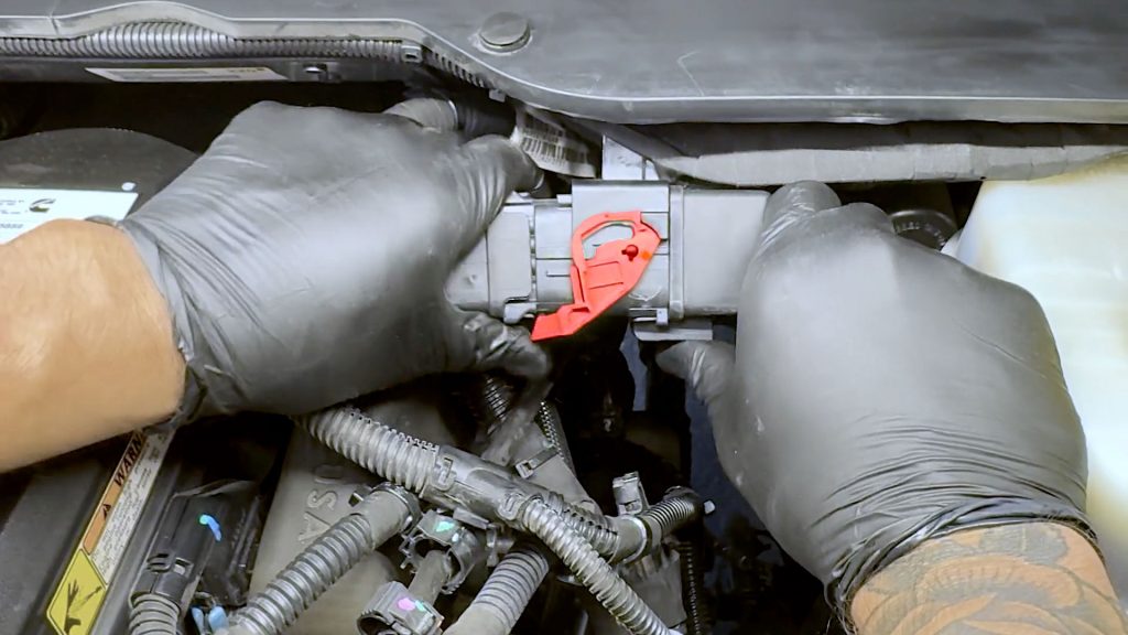
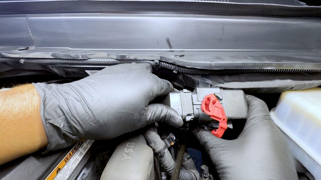
12. Rotate the lever on the large data cable to unlock and unplug it.
13. With a flat-blade screwdriver, free the final cable tie holding the harness.
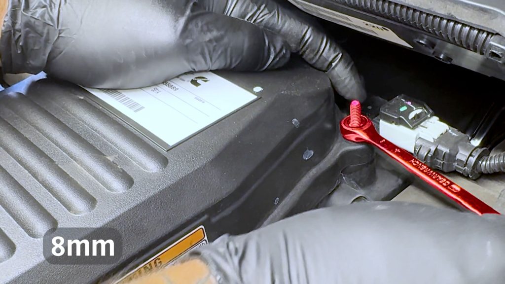
4. Free Engine Valve Cover
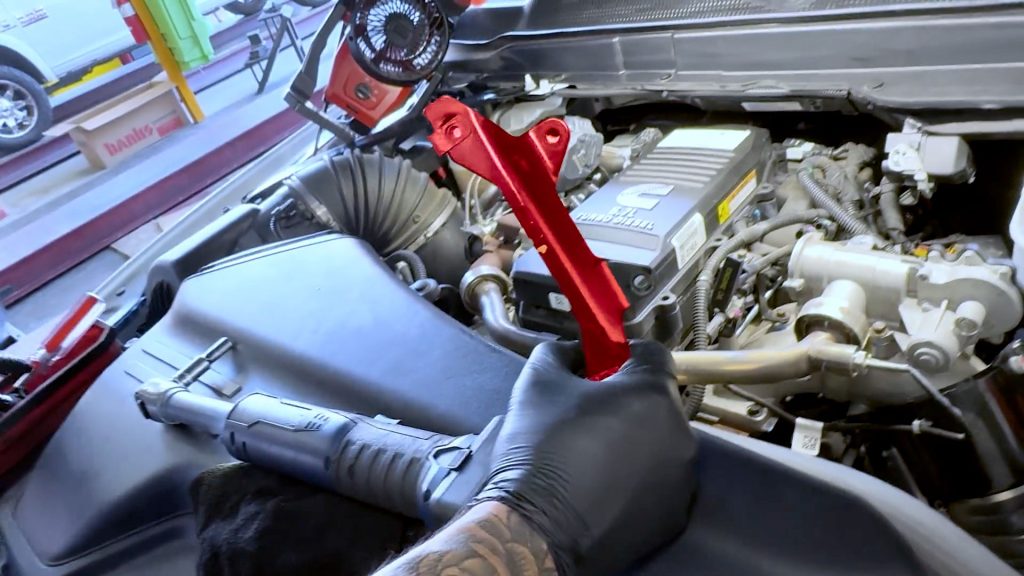
1. With an 8mm gear wrench, remove the two rear studs.
2. Remove the remaining 6 bolts to free the valve cover.
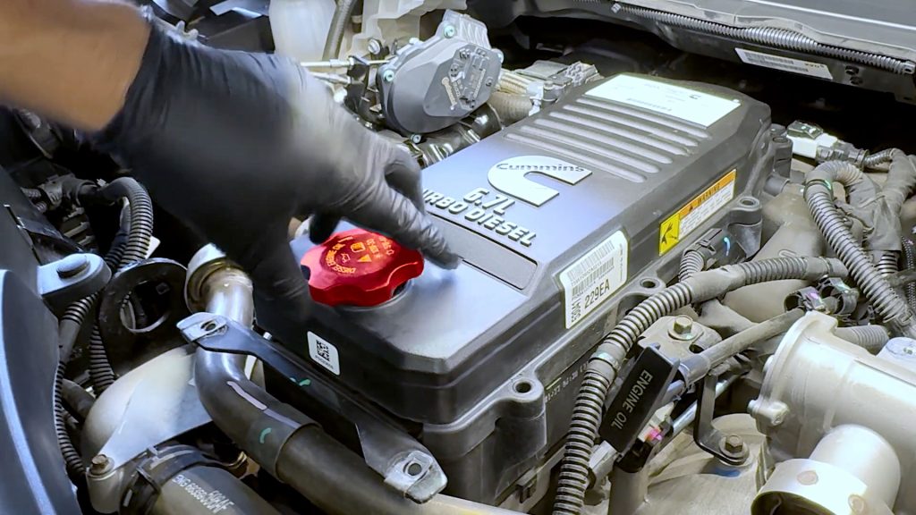
3. Unscrew the oil cap.
4. Now lift the cover to expose and remove the two remaining bolts that hold the engine cover bracket.
This bracket will not be reused.
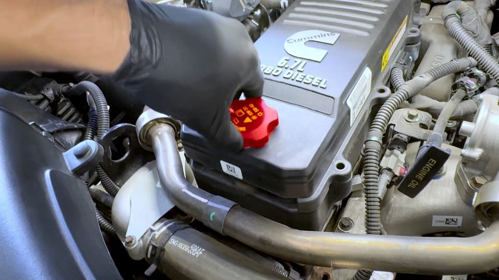
5. Replace the oil cap.
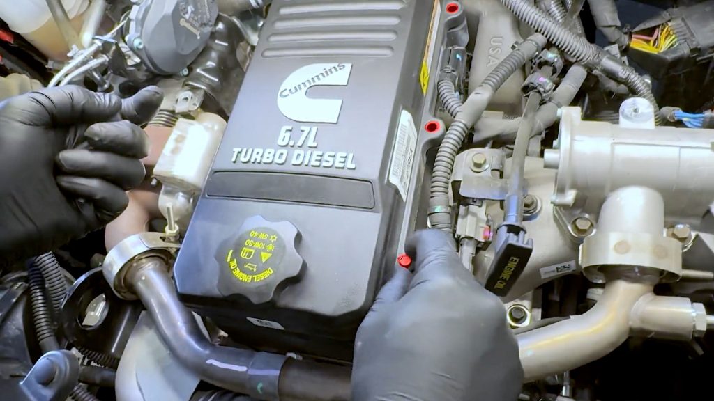
6. Replace the 5 bolts back into the valve cover.
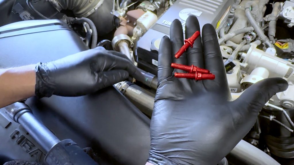
7. By hand, thread the 3 studs back into the rear of the valve cover.
8. Snug down all the bolts; do not over-tighten.
9. Use a gear wrench to snug down the rear studs.
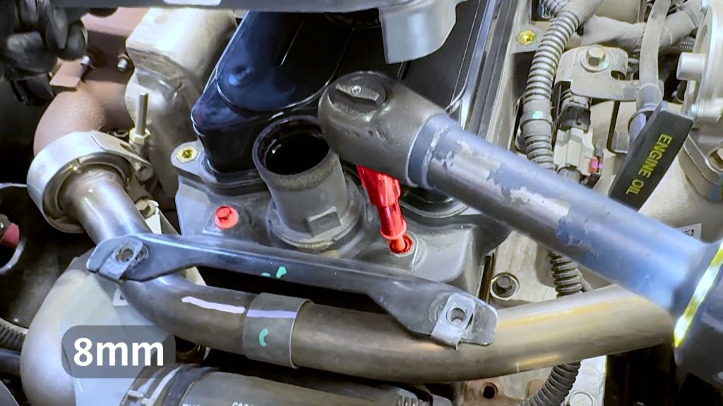
5. EGR Crossover Removal
1. With an 8mm deep socket, remove the bolt that holds the P clamp to the engine.
The P clamp can be discarded; it will not be reused.
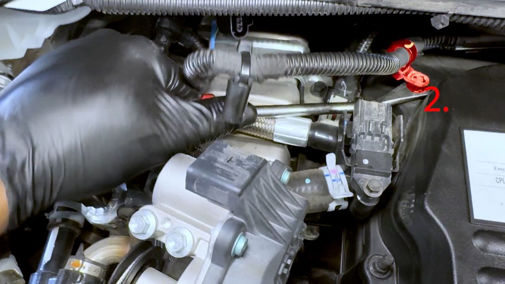
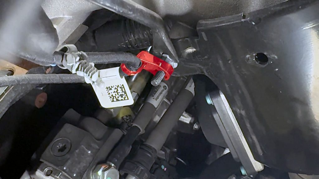
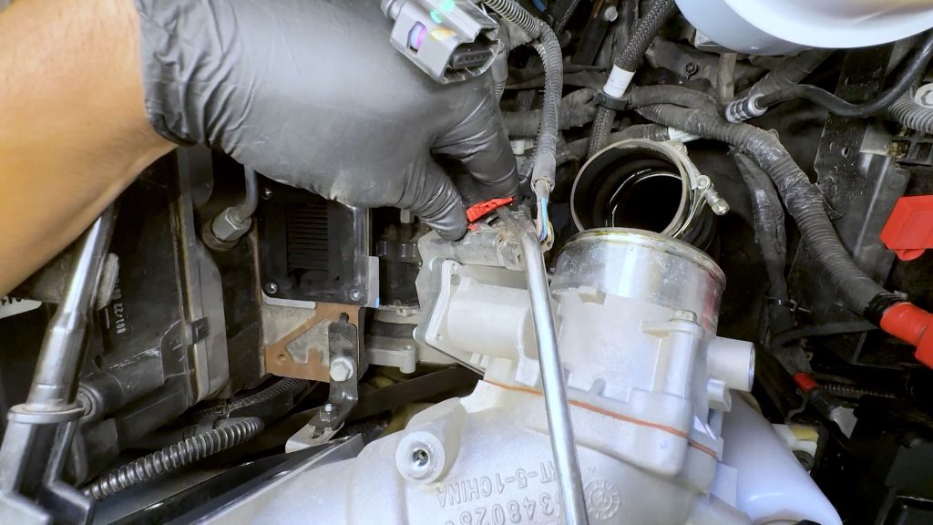
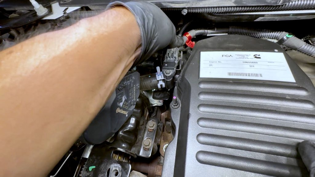
2. With a flat-blade screwdriver, free the EGR temp sensor plug.
3. Pop the black cover off to expose the red safety tab.
4. Use a flat-blade screwdriver to slide the red safety tab over.
5. Depress the back of the grey plug to free the EGR temp sensor plug.
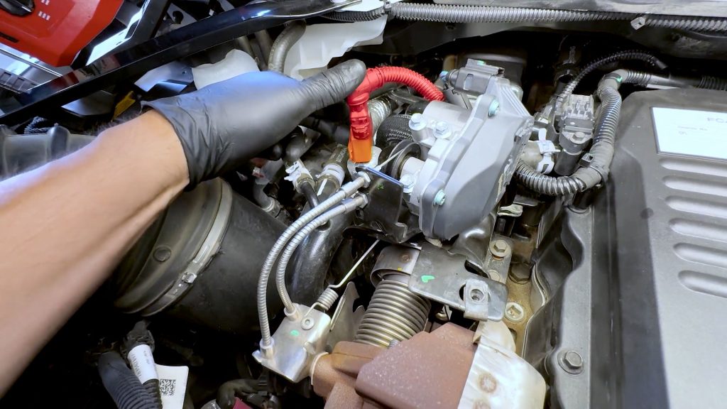
6. Follow the harness, with a flat blade screwdriver, free the wire from the cable ties on the throttle heat shield.
There are 2 cable ties to free.
7. With a deep socket, loosen the v-band clamp, but don’t fully remove it.
8. Do the same with the passenger side v-band clamp.
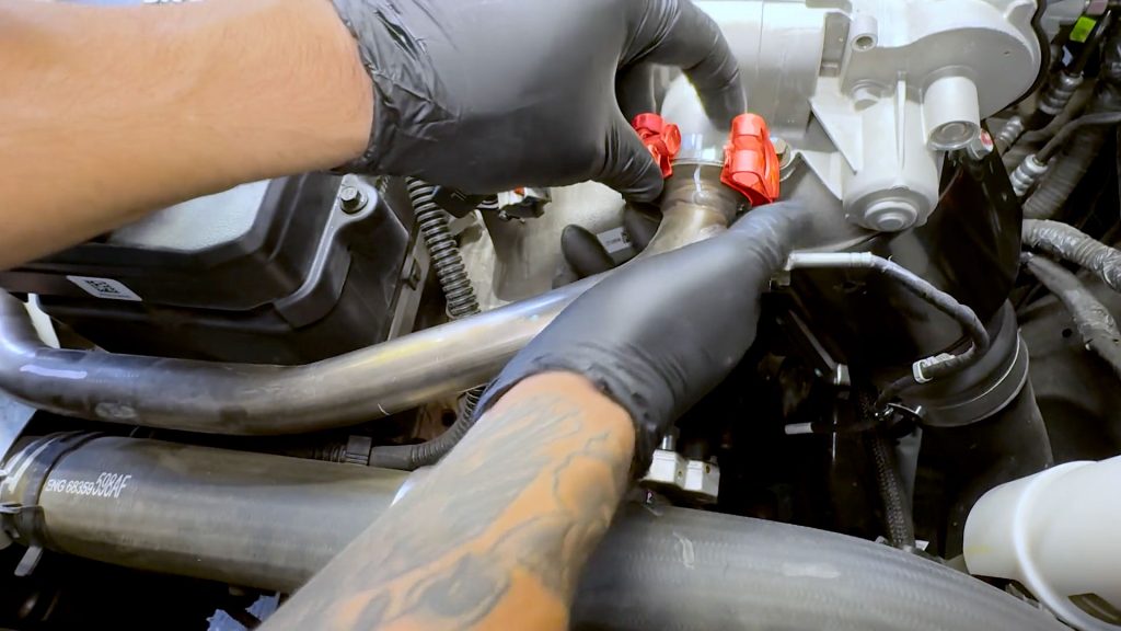
9. With your hand supporting the driver side of the crossover tube, rotate the v-band clamps so they are facing up.
10. Slide the passenger side v-band
11. Pull with your right hand to free the EGR tube from the valve, catching the conical gasket on the right, while also catching the flat gasket on the left side by the EGR cooler.
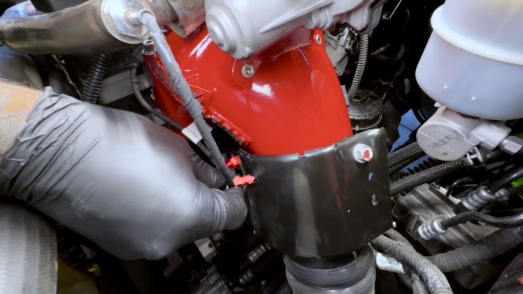
12. With the EGR crossover tube out of the way, remove the two bolts securing the throttle heat shield and set it aside.
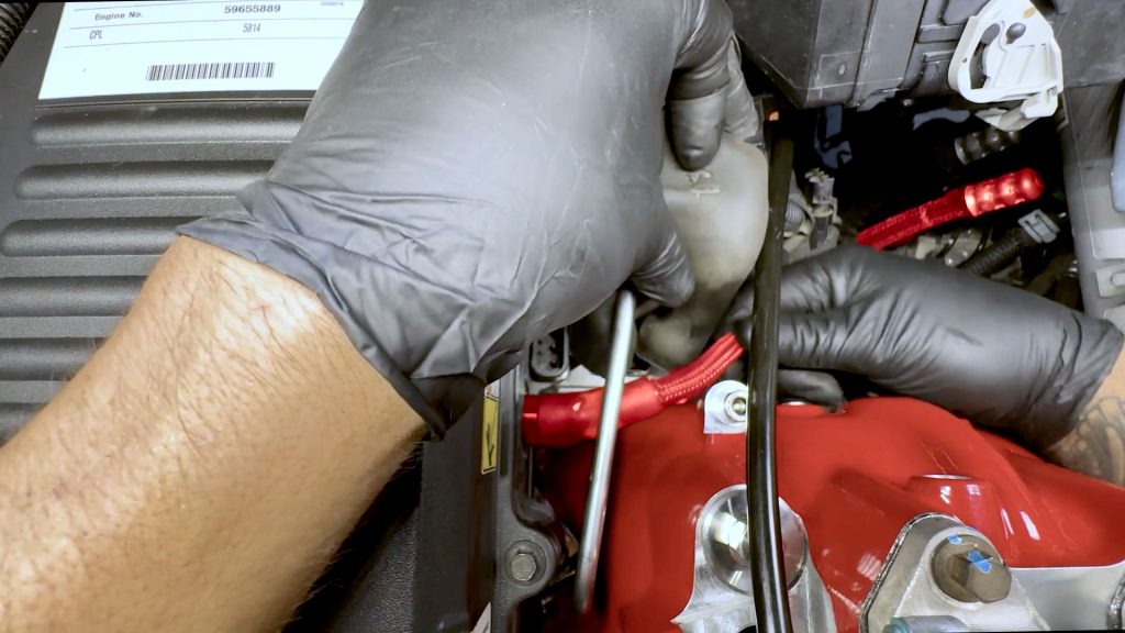
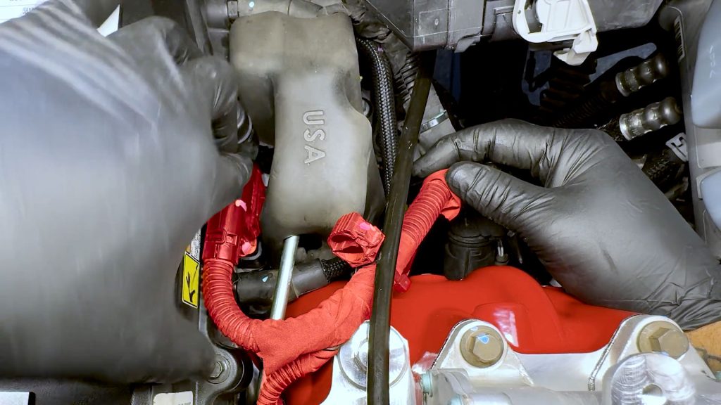
6. Free 12V Heater Wire
1. Free the cable tie from its bracket underneath the dipstick.
2. Follow the harness and free the next cable tie from the dipstick tube.
3. Follow the harness and free the second cable tie from the dipstick tube.
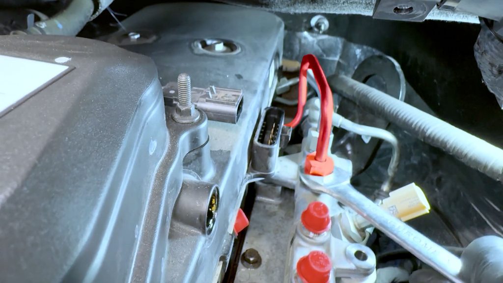
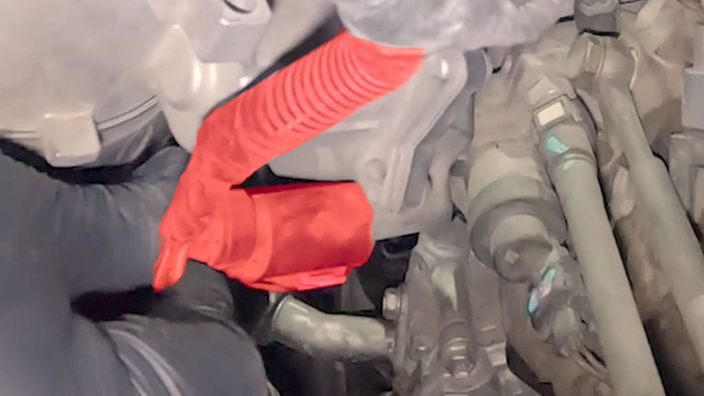
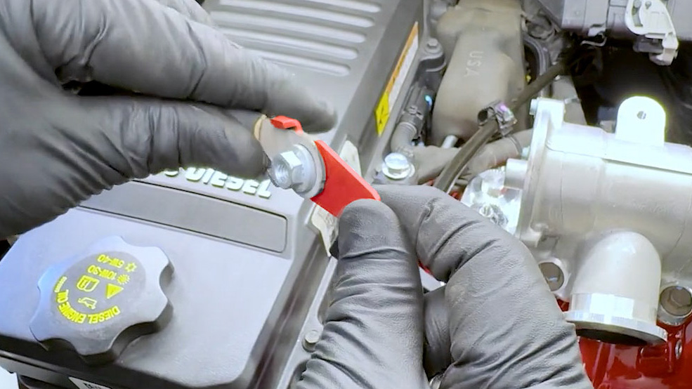
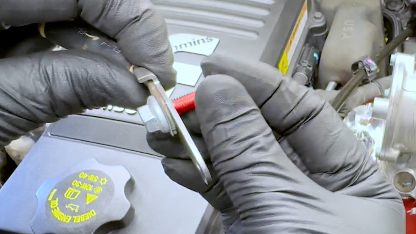
4. With a deep socket and extension, loosen the captive nut holding the 12V heater wire to the grid heater post.
5. Move the 12V power lead up and out of the way.
6. Remove the bolt holding the dipstick tube to its support bracket.
7. Once free, lift the dip stick tube up a few inches to provide extra clearance for the Monster-Ram.
7. Factory Intake Elbow Removal
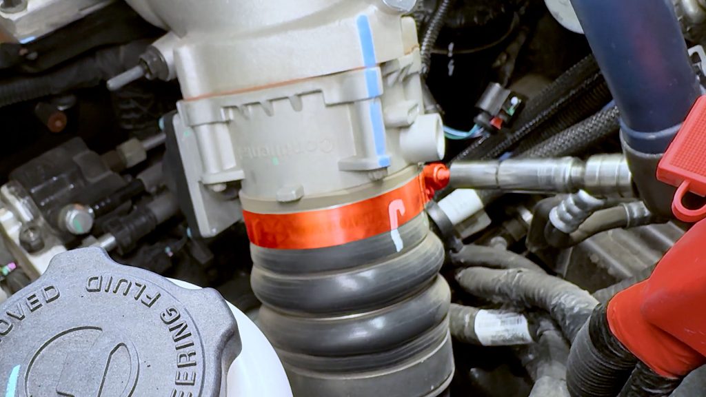
1. Loosen the clamp that holds the factory boost tube to the throttle inlet, but don’t fully remove it.
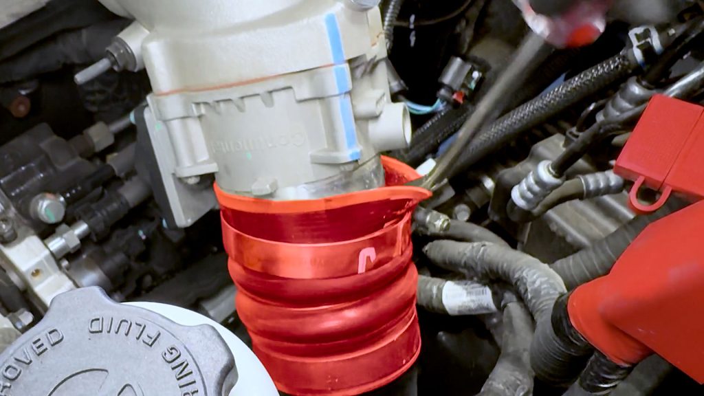
2. With a flat blade screwdriver, carefully break the boost tubes grip around the throttle. This will ease the removal of the elbow later.
3. With a flat-blade screwdriver, depress the tab of the large blue injector plug next to the front PCV hose and free it from the side of the valve cover.
4. With a flat blade screwdriver, rock the end of the PCV hose loose while pulling from the opposite end.
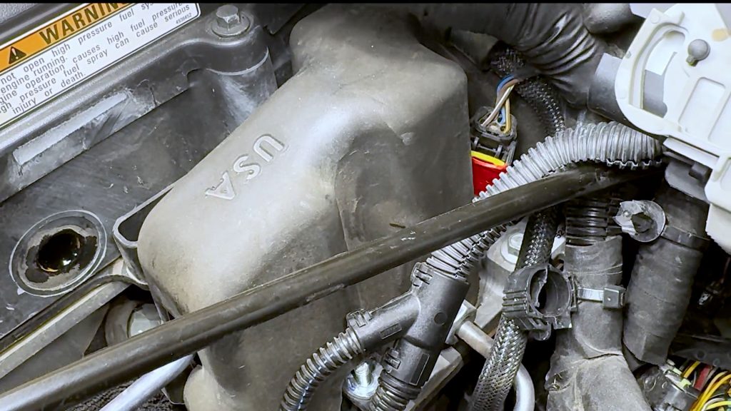
5. With an open-end wrench, remove the PCV barb from the valve cover.
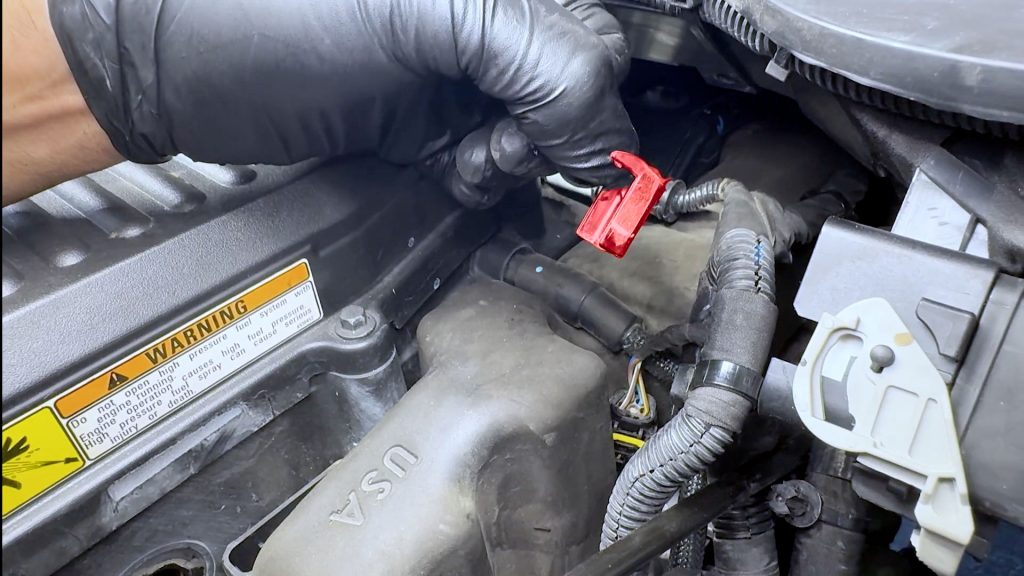
6. On the top of the intake elbow, locate the plug on the back side of the EGR valve. Use a flat-blade screwdriver to slide the locking tab back first.
7. Depress the end of the plug to free it from the EGR valve.
8. Locate the MAP sensor under the EGR valve, and unplug it.
9. On the back side of the stock intake elbow, pop the plastic cable tie free from the elbow with a flat head screw driver.
10. With an extension and a deep socket, loosen the 6 bolts that hold down the intake elbow to the grid heater plate.
11. Use a telescopic magnet tool to lift the bolts up and out.
12. Rotate the factory intake horn towards the front of the truck to free it from its boost tube and expose the throttle valve plug.
13. With a flat-blade screwdriver, remove the black plastic cover from the sensor plug to reveal its red safety tab.
14. Slide the red locking tab with a flat blade screwdriver and unplug the throttle from the wire harness.
15. The factory intake horn and EGR valve can now be removed and set aside on a workbench.
8. Fuel Rail & Grid Heater Removal
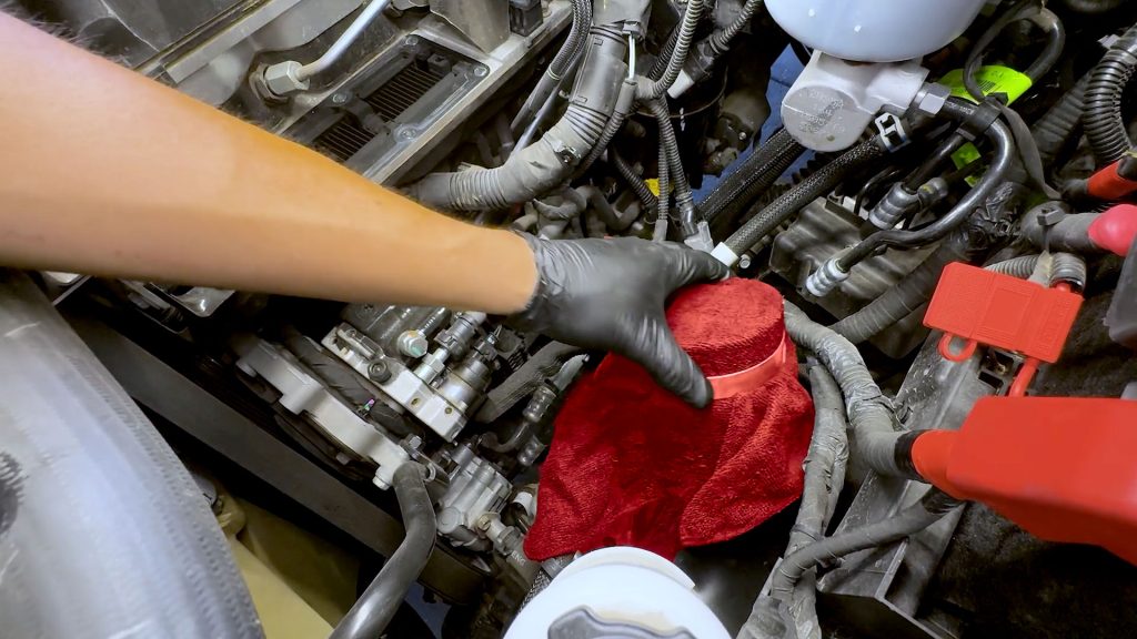
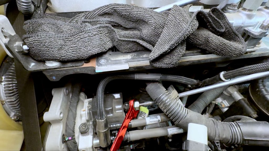
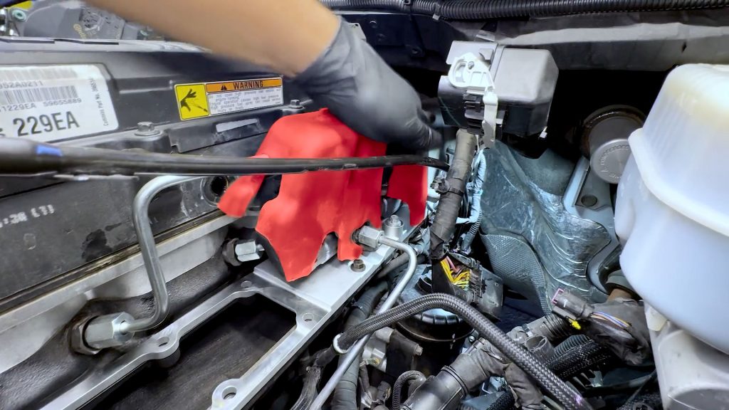
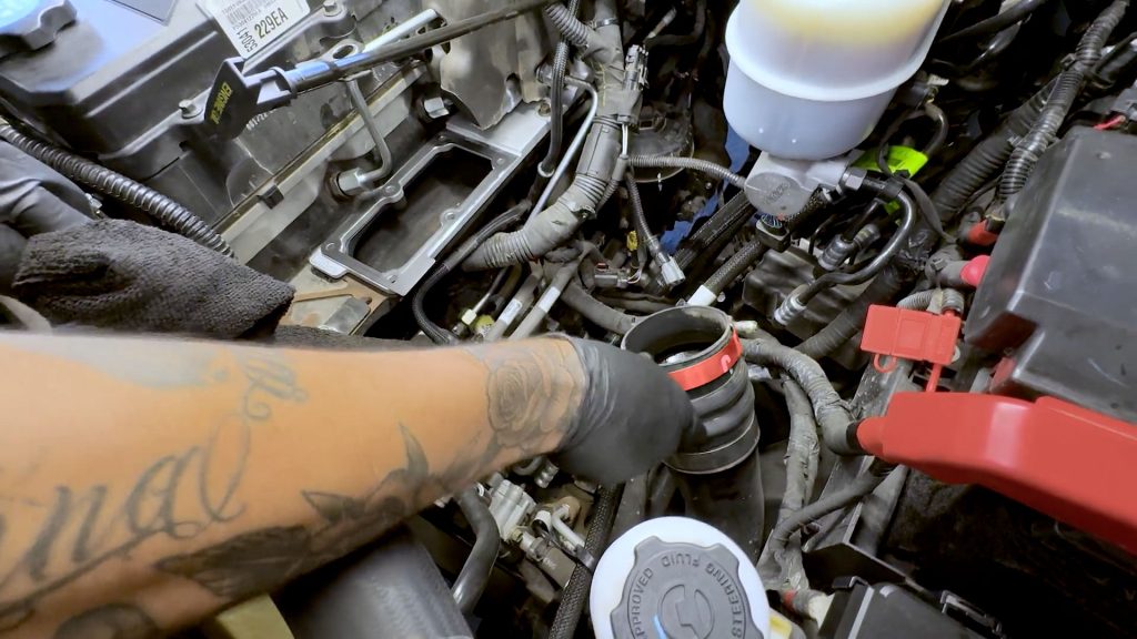
1. Start by covering the factory boost tube outlet with a rag to prevent any debris from falling in. Secure the rag with the clamp.
2. Cover the top of the grid heater with a rag as well.
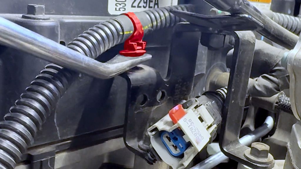
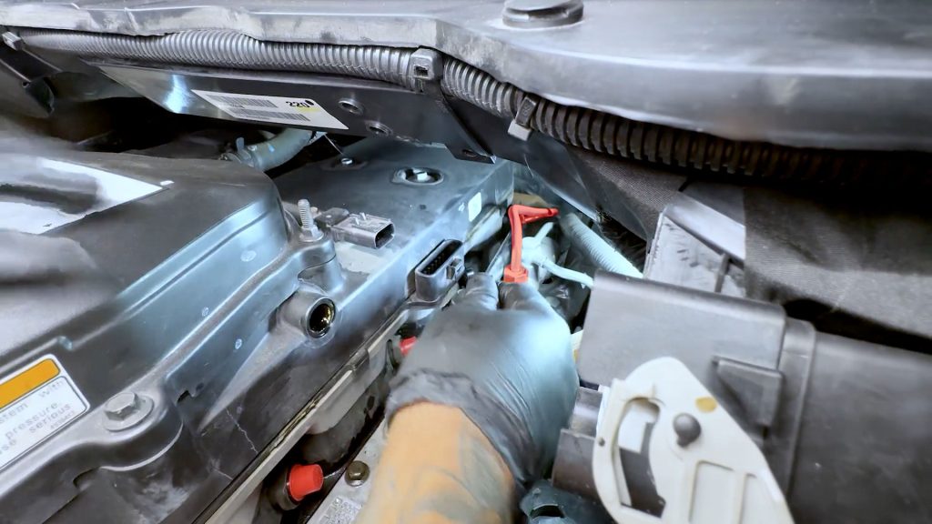
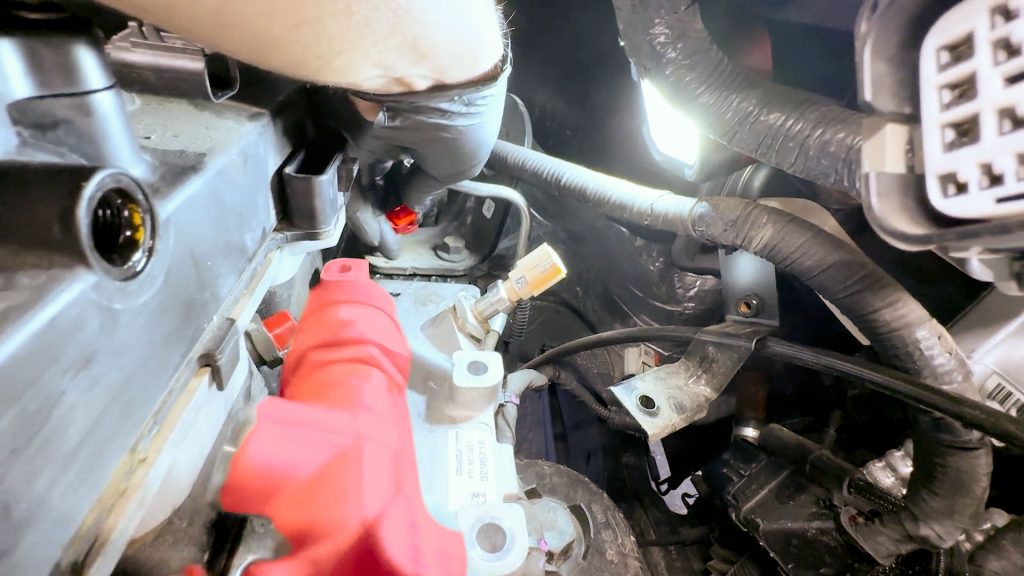
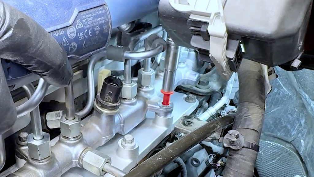
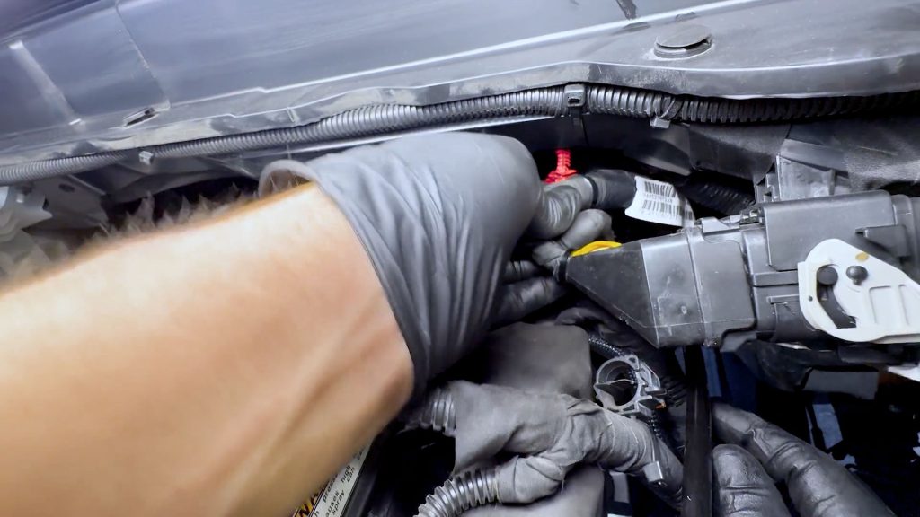
3. Locate the fuel pressure sensor in the middle of the rubber isolator.
4. Pop off the plastic cover protecting the plugs’ locking tab.
5. Slide the exposed yellow locking tab up, and depress it to free the plug from the sensor.
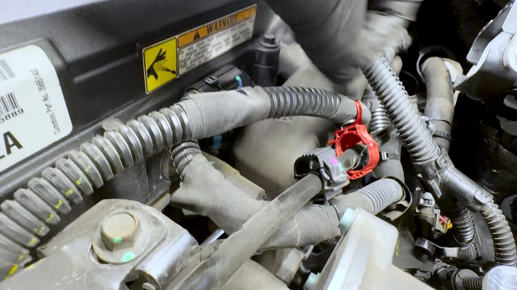
6. Lift the black plastic cover off the plug near the rear of the valve cover to expose the locking tab.
7. With a flat blade screwdriver, slide the locking tab towards the rear of the truck.
8. Unplug the harness from the valve cover.
9. With a flat-blade screwdriver, rock the rear PCV hose off its barb to free it.
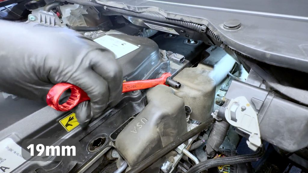
10. Use an open-ended 19mm wrench to unscrew the rear barb from the valve cover.
11. Lift the rubber isolator up and out of the engine bay.
12. Pop the black plastic cover off the temperature sensor on the back of the intake manifold plate. It is on the back side of the plug.
13. Slide the sensors’ red locking tab down towards the floor to unlock it.
14. Depress the plug to free the harness from the sensor.
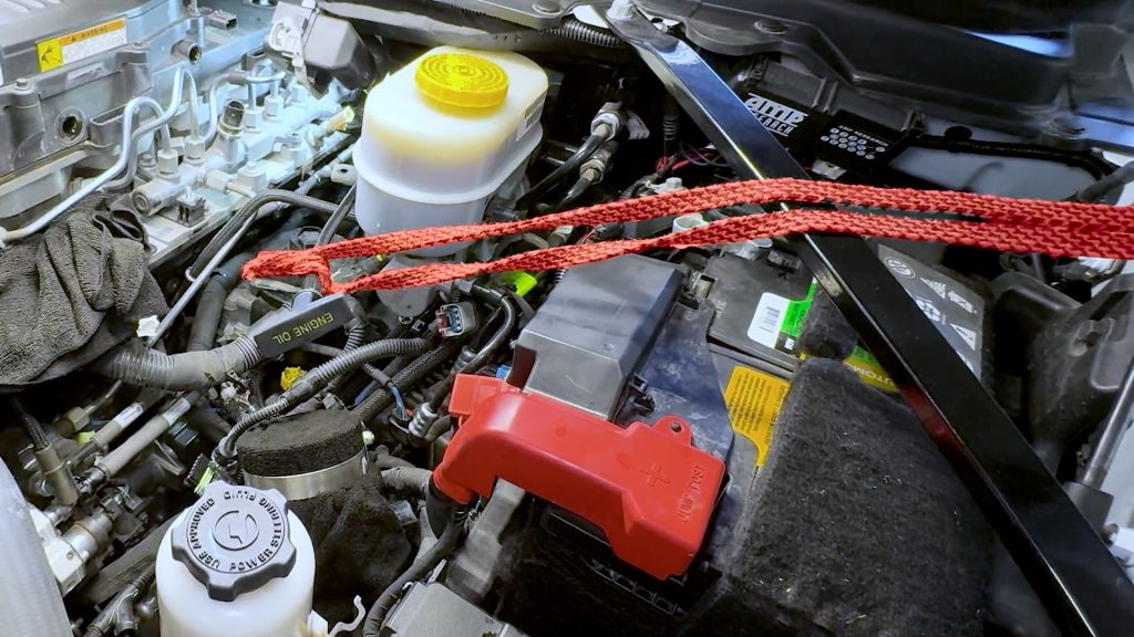
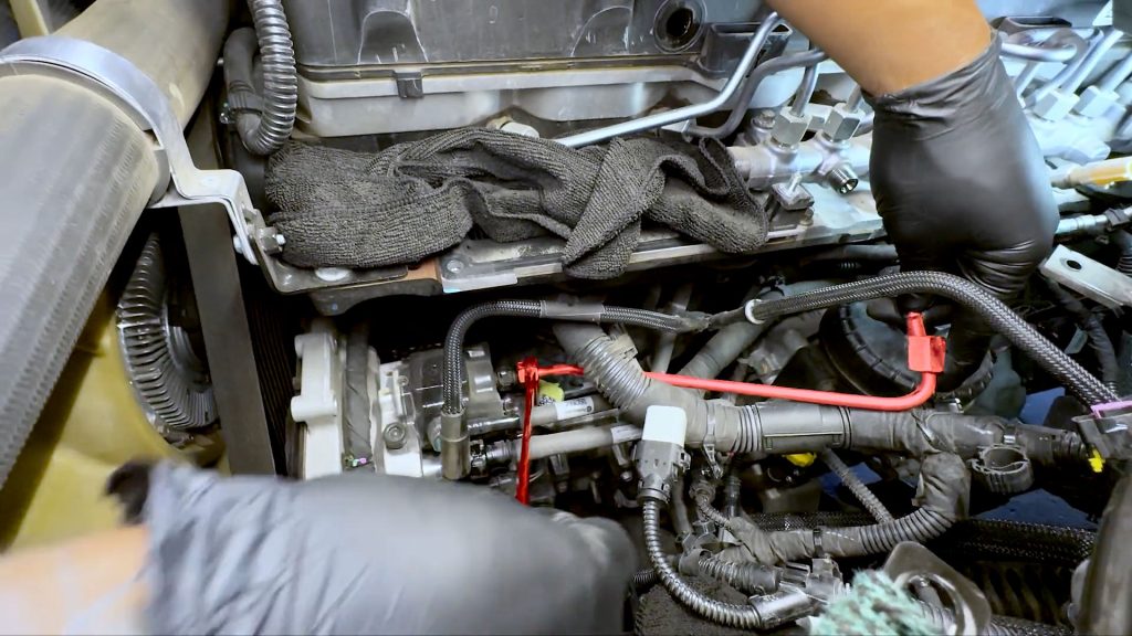
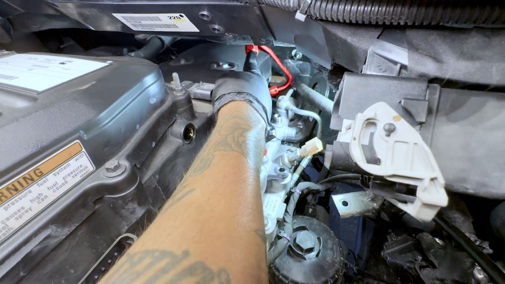
15. Use a bungee cord to hold the dipstick tube off to the side to provide extra clearance to work on the fuel lines.
16. Remove the bolt that holds down the dip stick support bracket.
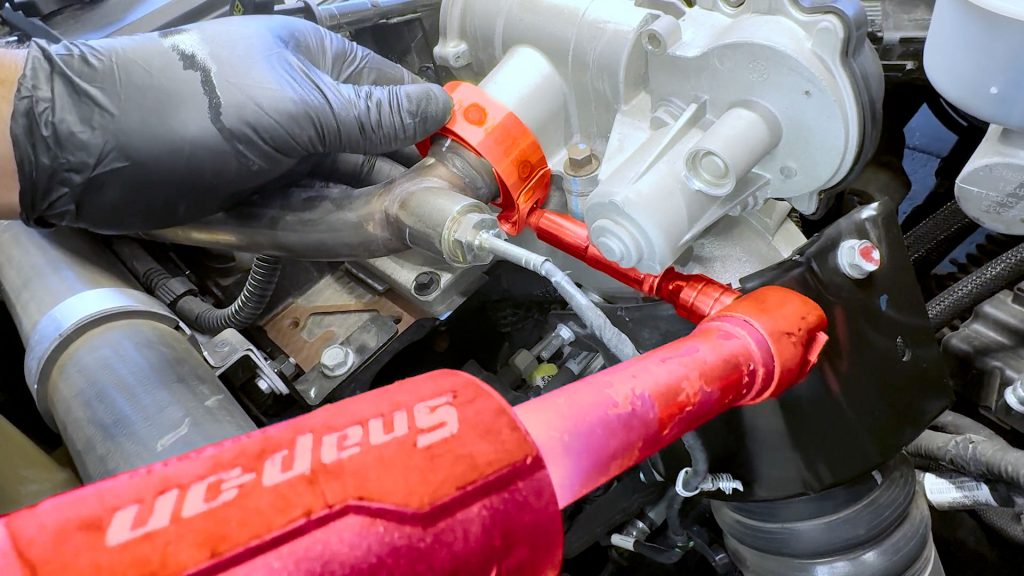
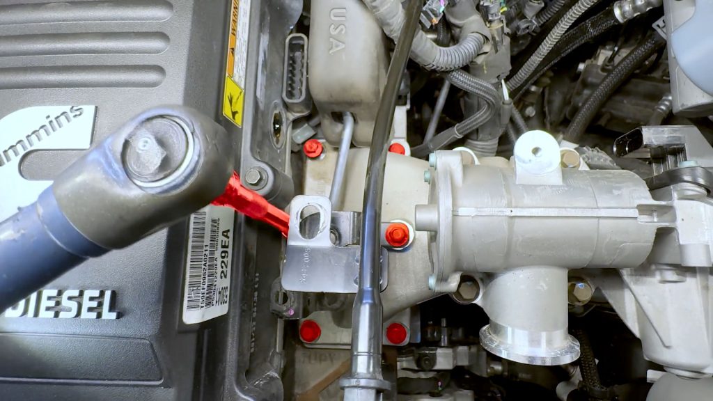
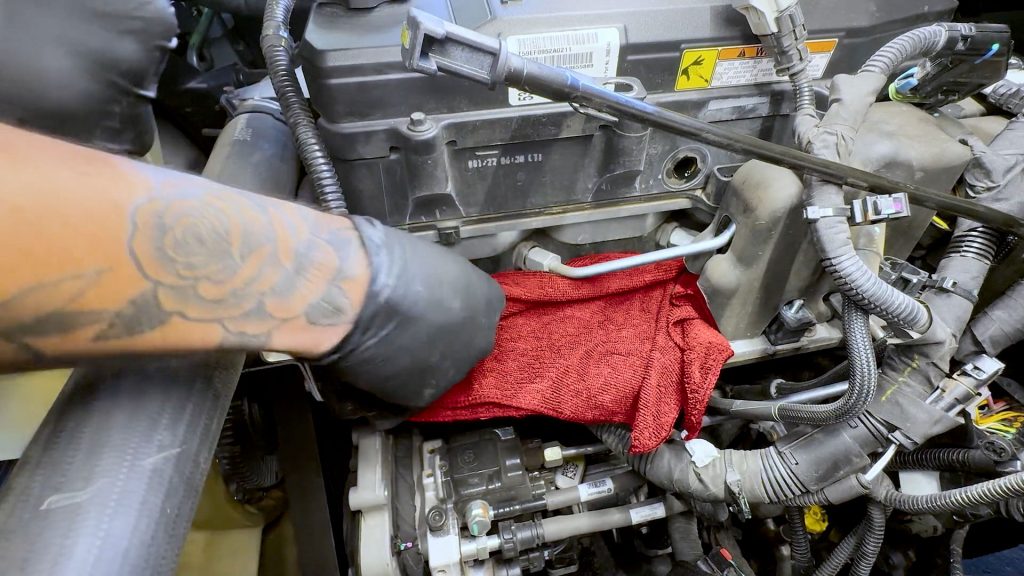
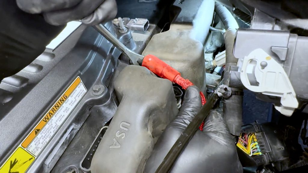
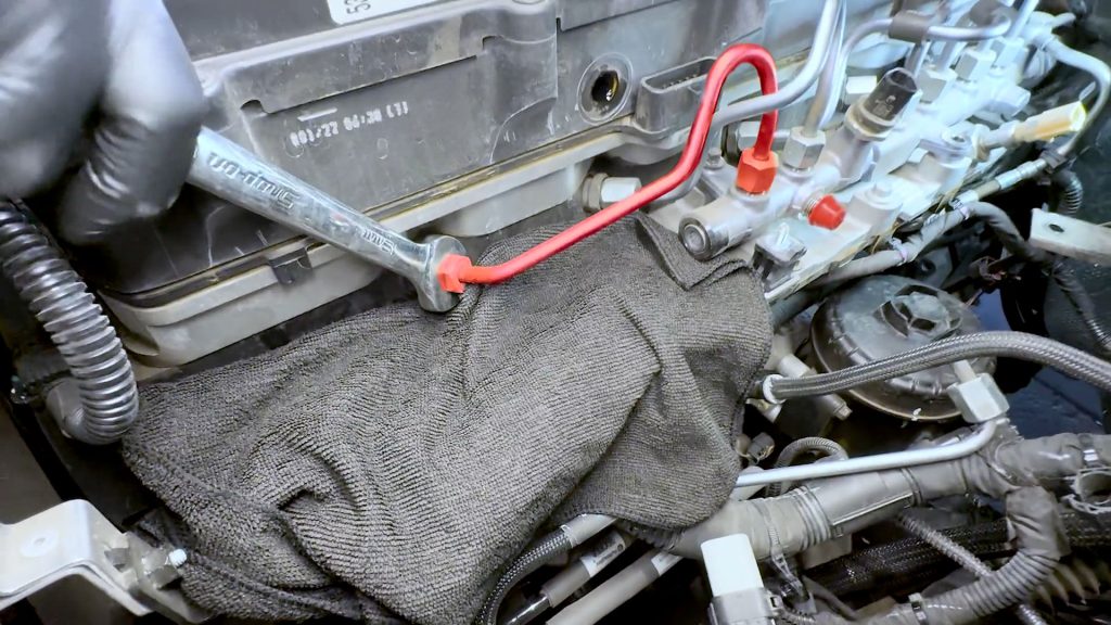
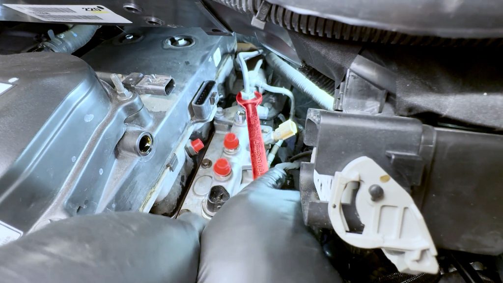
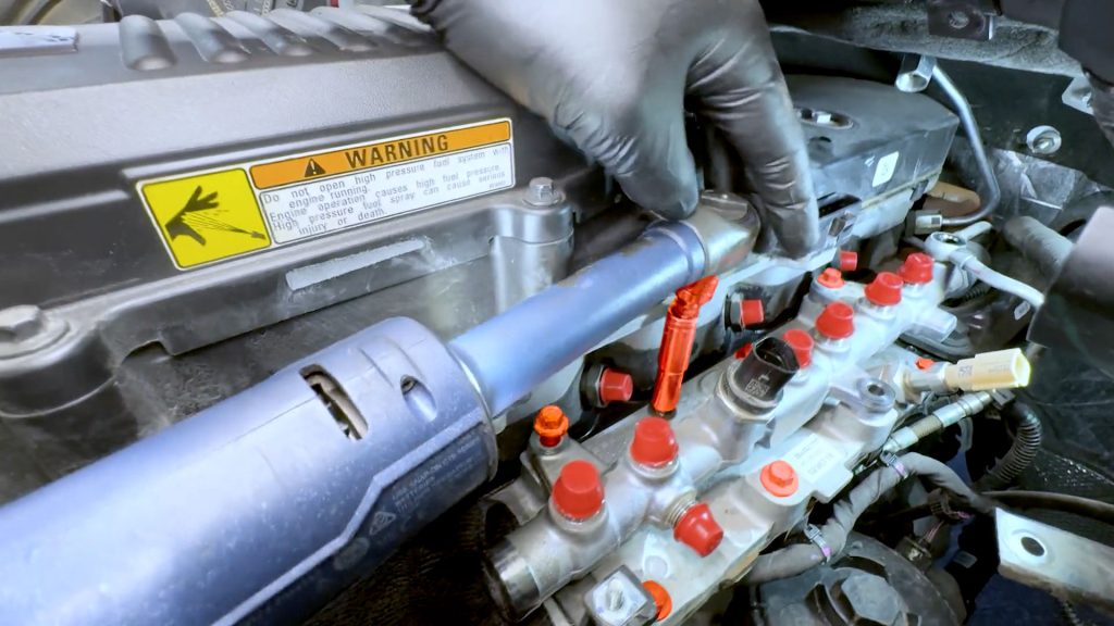
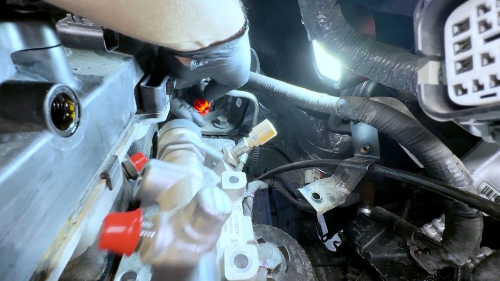
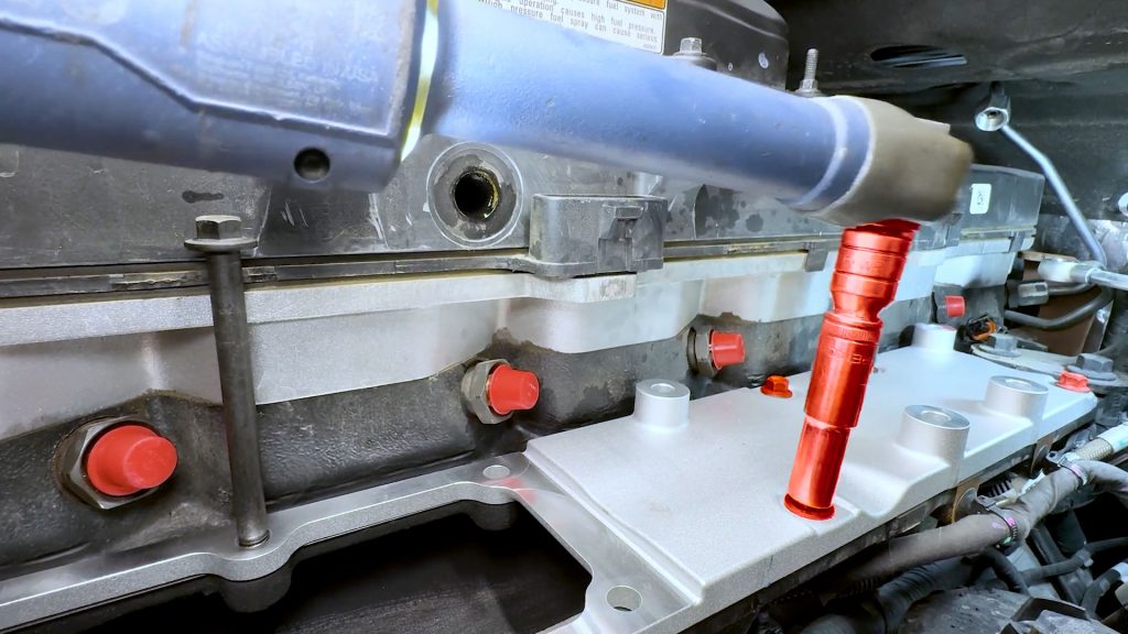
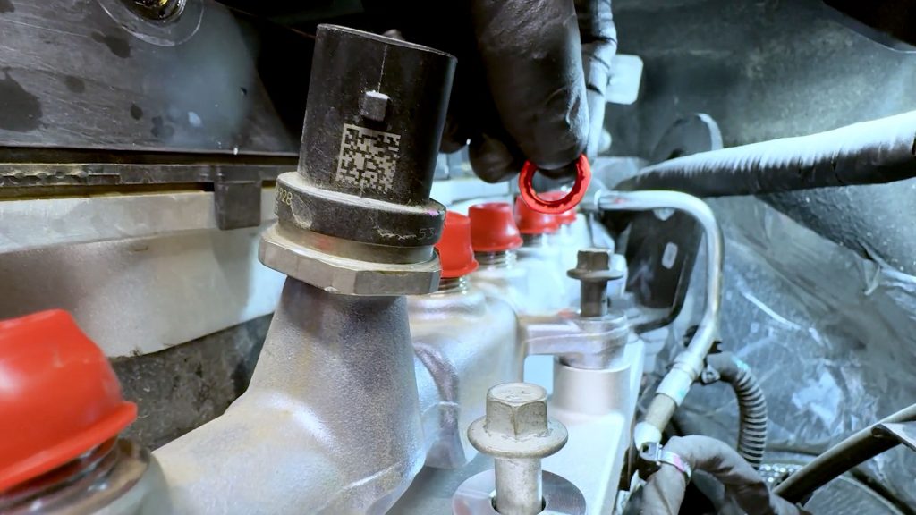
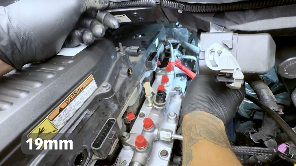
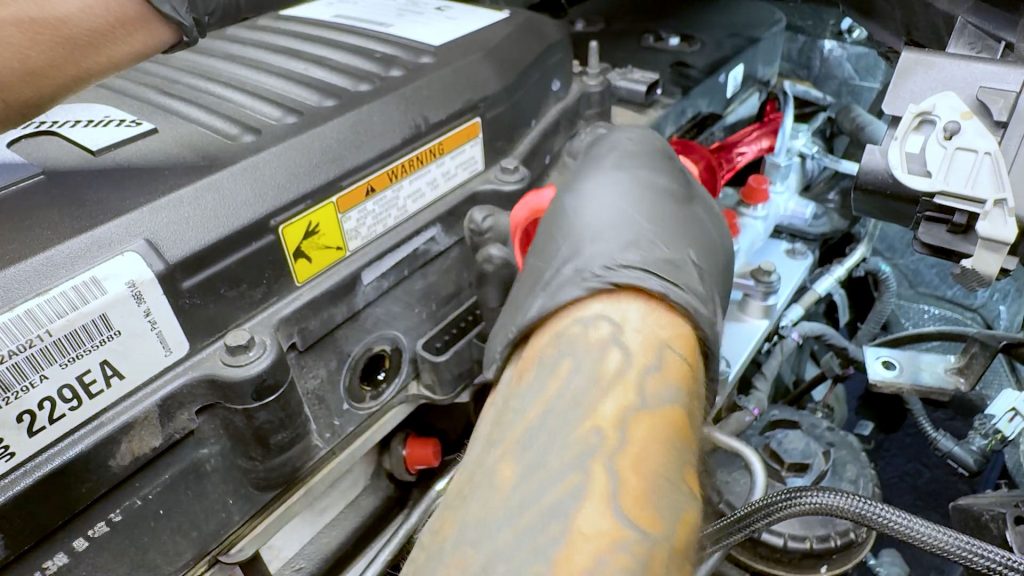
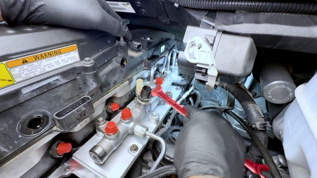
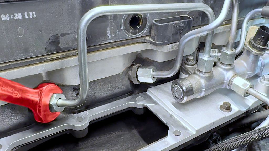
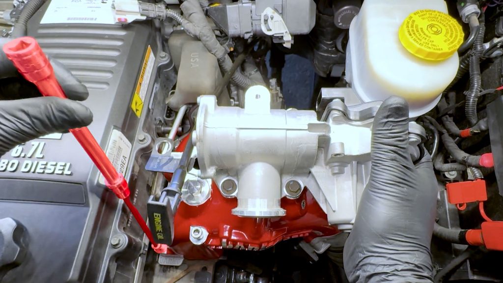
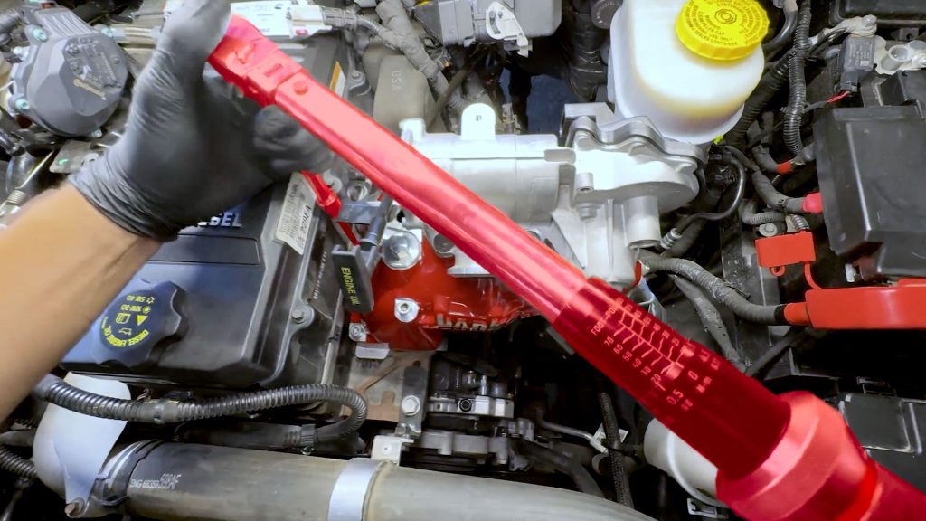
17. With a 19mm wrench, loosen the high-pressure fuel feed line from the fuel rail.
18. Follow the line down and loosen the other end slightly from the high-pressure fuel pump. This does not have to be fully removed.
19. Rotate the high-pressure fuel line out of the way, and snug it down so it won’t leak.
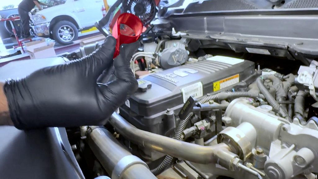
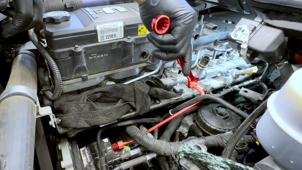
20. Place a cap on the high-pressure feed line to the fuel rail.
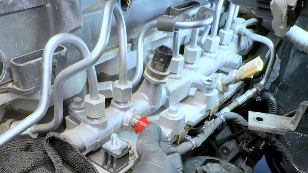
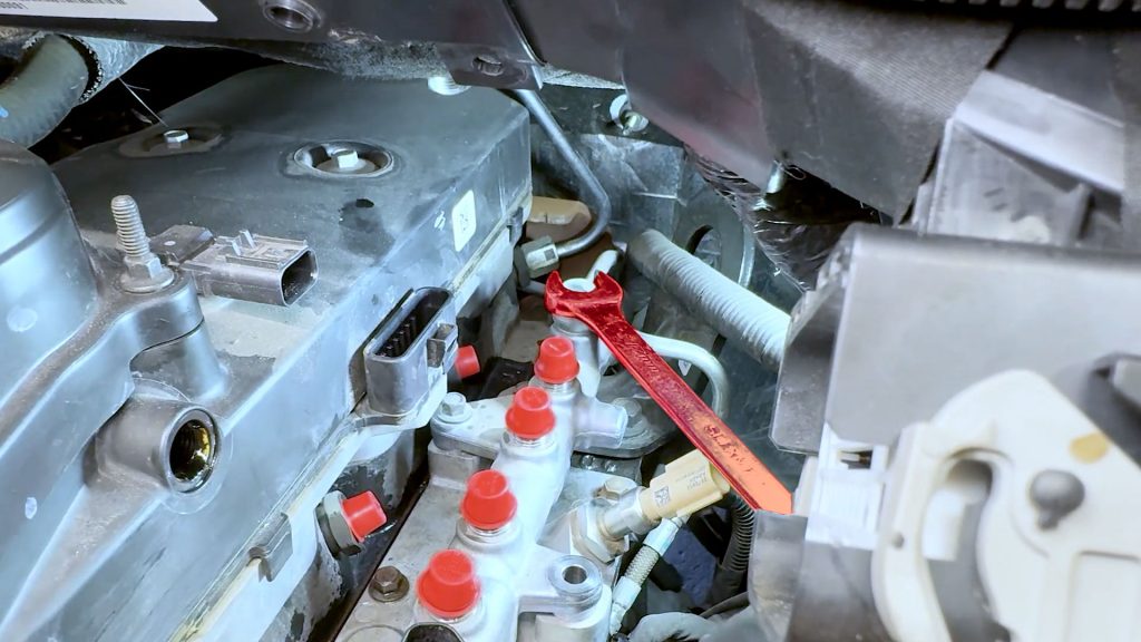
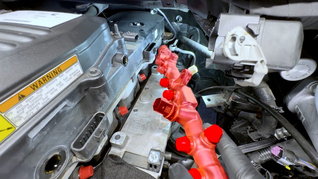
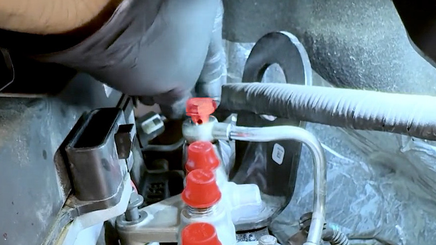
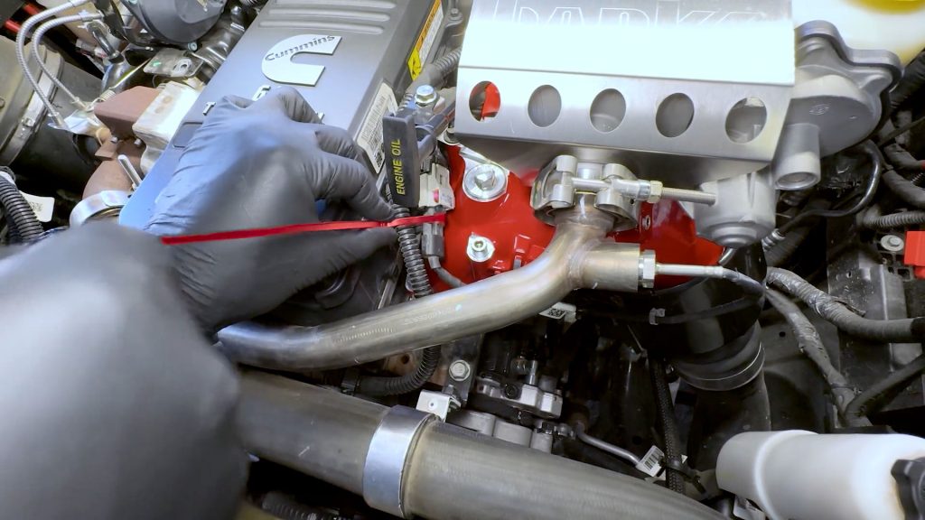
21. Locate the #1 fuel line, with a 19mm wrench, remove it.
When removing the factory fuel lines, use a black Sharpie to label each one so they do not get mixed up.
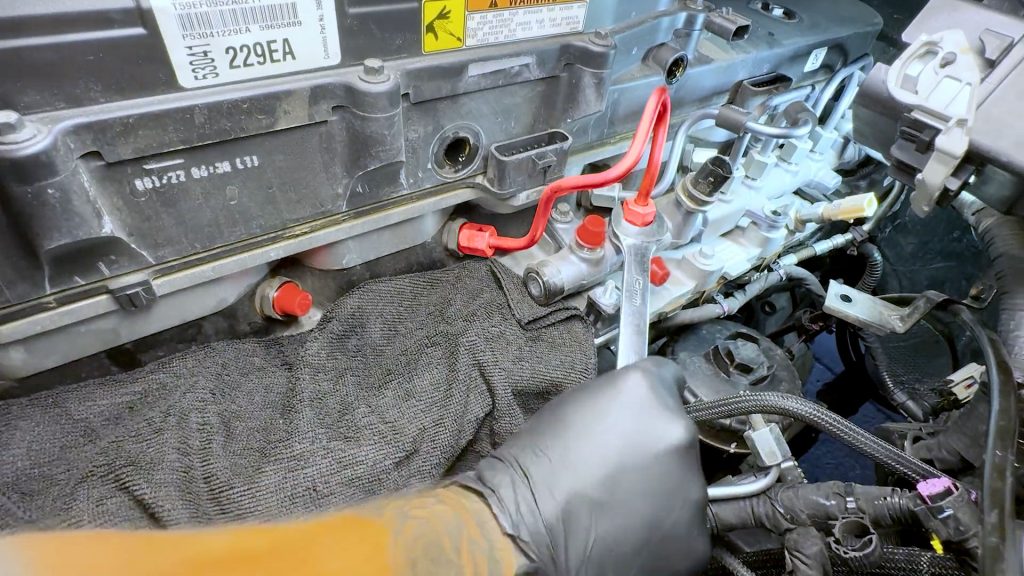
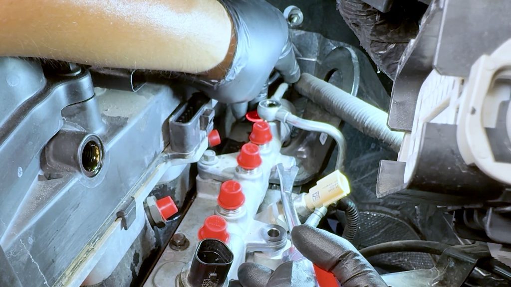
22. Place caps on the #1 fuel injector and fuel rail, and continue to the #2 fuel line.
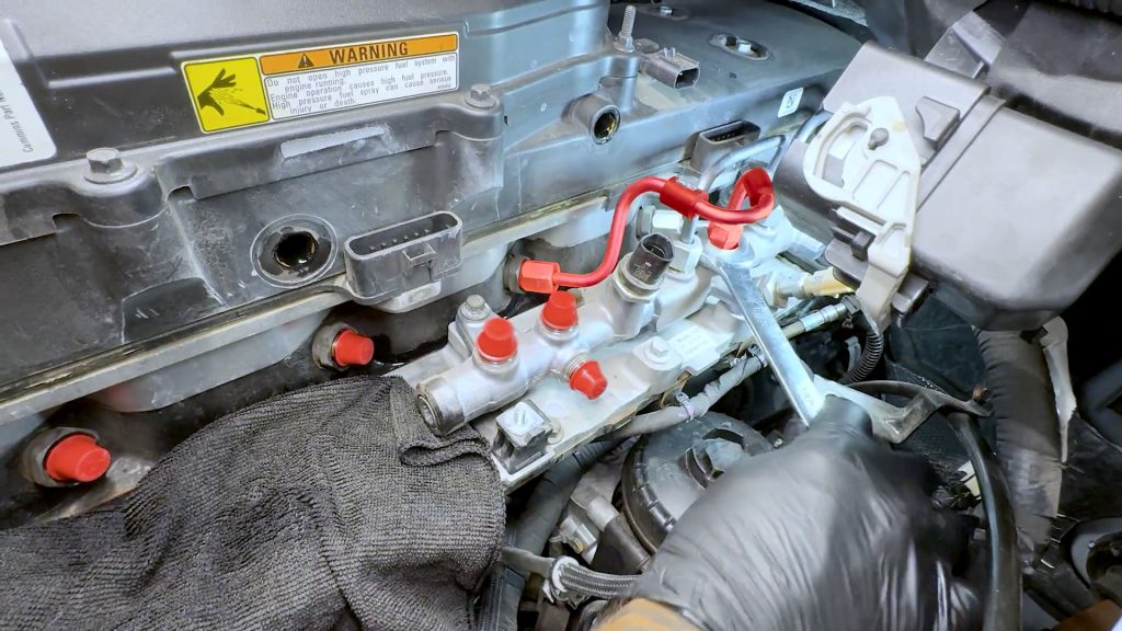
23. Place caps on the #2 fuel injector and fuel rail, and continue to the #3 fuel line.
24. Place caps on the #3 fuel injector and fuel rail, and continue to the #4 fuel line.
25. Place caps on the #4 fuel injector and fuel rail, and continue to the #5 fuel line.
26. Place caps on the #5 fuel injector and fuel rail.
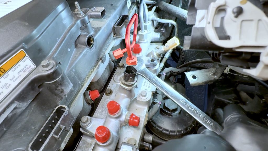
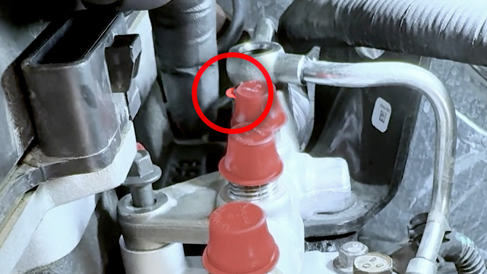
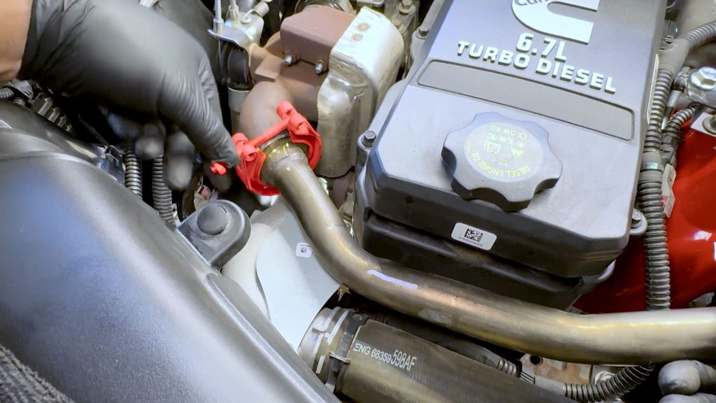
For the #6 fuel line, loosen the end on the cylinder head slightly, but do not fully remove it. It is difficult to reach and just needs to be loosened a few turns
27. Fully loosen the fuel rail end of the #6 fuel line.
28. Now you can rotate the #6 fuel line up and out of the way.
29. Loosen and remove the rear banjo bolt from the fuel rail.
30. Take care not to lose the banjo bolt’s washer. It will be reused.
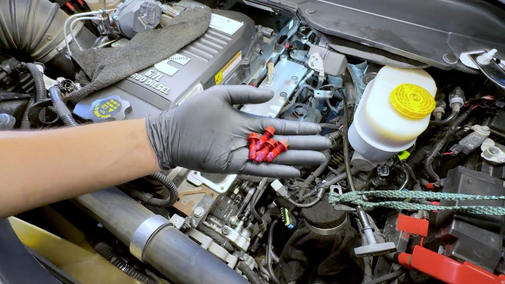
31. Loosen and remove the remaining 7 bolts holding down the fuel rail and intake manifold plate.
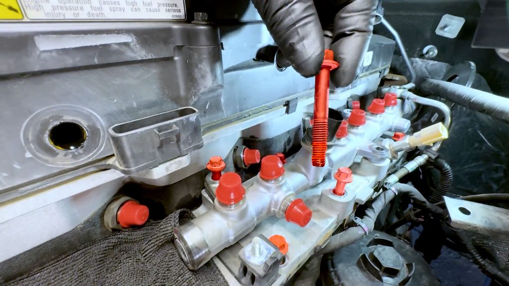
Set them aside; some are different sizes, so take care not to mix them up.
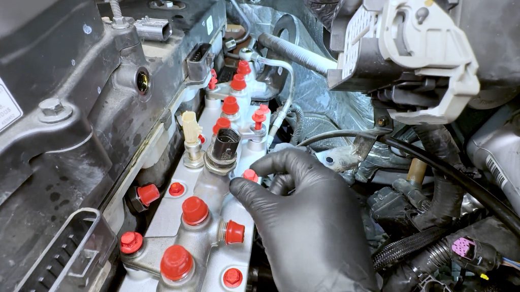
32. Lift the fuel rail slightly, take care, as there is one last sensor at the end of the fuel rail to unplug.
You do not want to damage this sensor.
Carefully unplug the final fuel rail pressure sensor at the end of the fuel rail
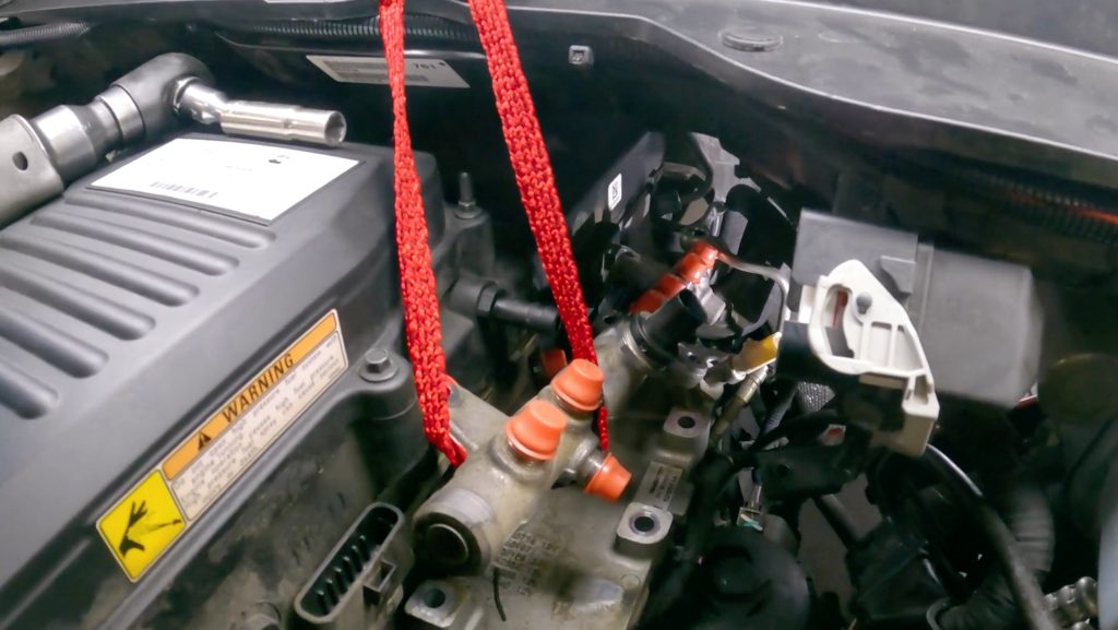
If the sensor feels too difficult to unplug safely, the fuel rail can be lifted up and out of the way with a bungee cord as an alternative.
33. Carefully lift and remove the fuel rail. Set it aside for now.
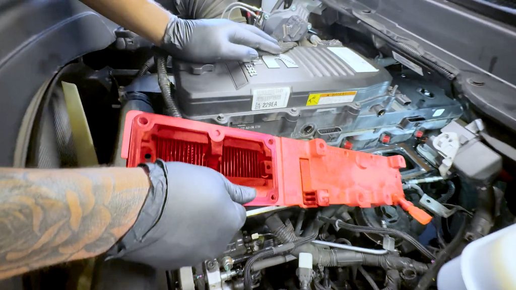
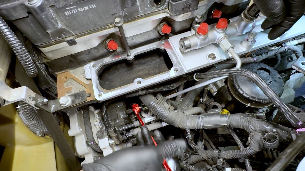
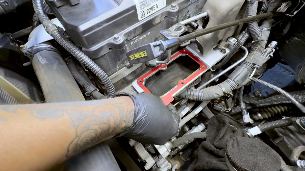
34. Carefully lift and remove the grid heater plate. Bring it to a workbench.
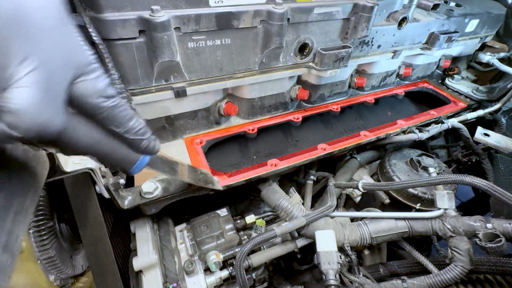
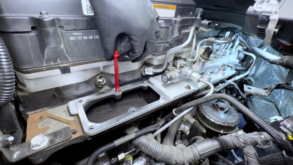
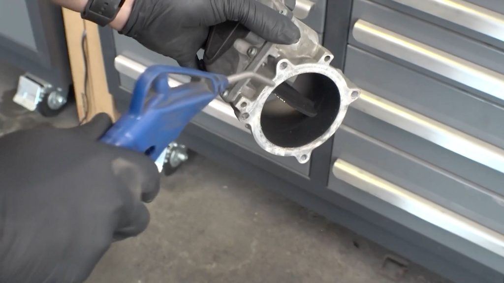
35. Remove any leftover gasket material from the intake manifold surface. Take care not to gouge the aluminum.

36. A shop vac is useful to vacuum up and remove any debris in the intake manifold.
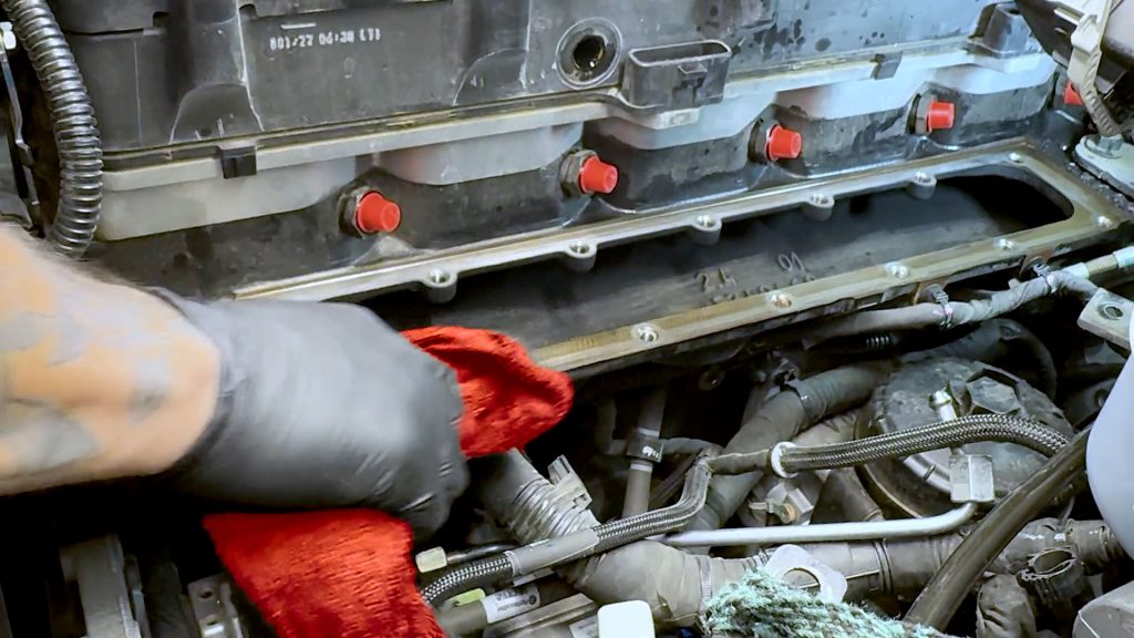
Be sure the mating surface is clean.
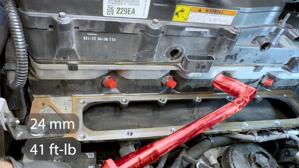
Important:
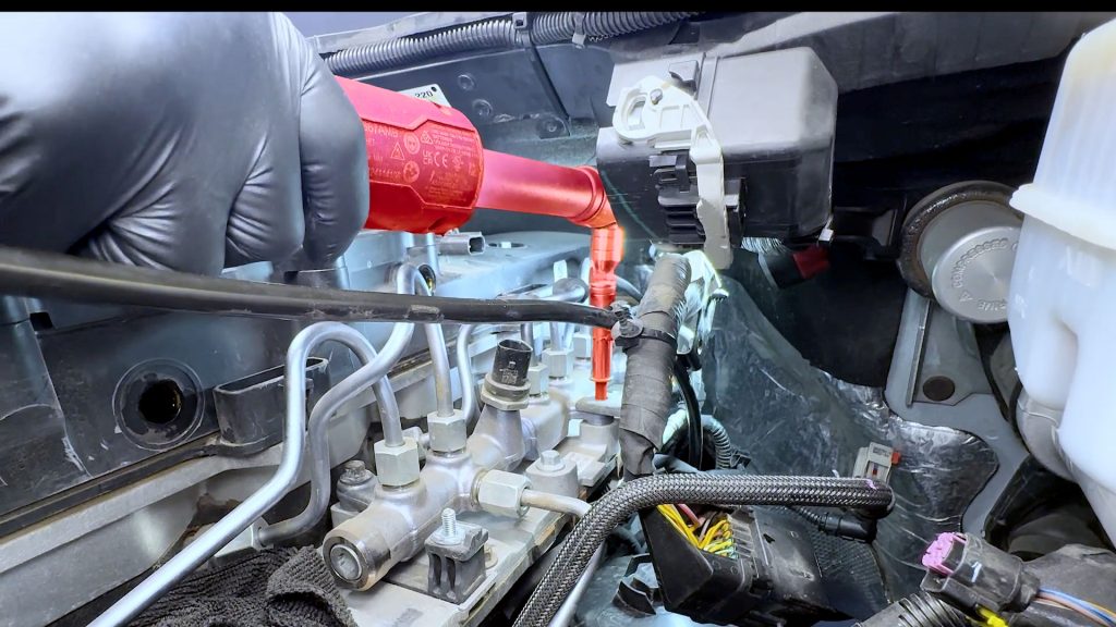
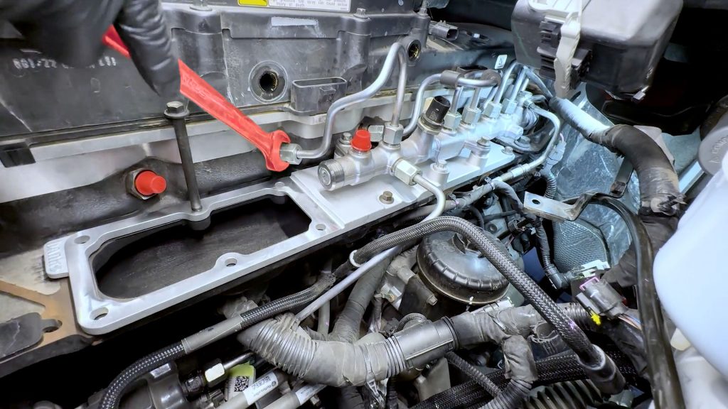
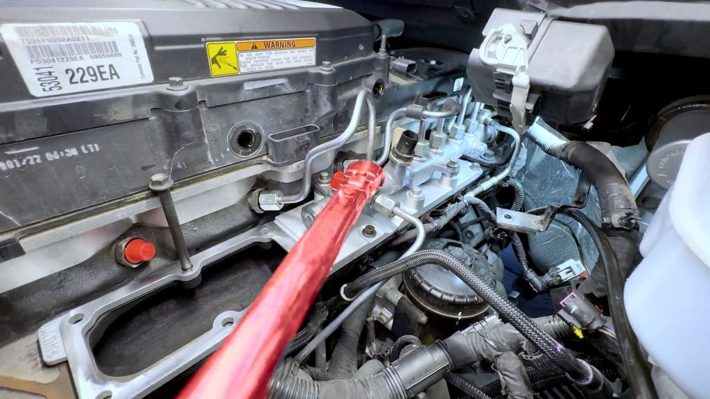
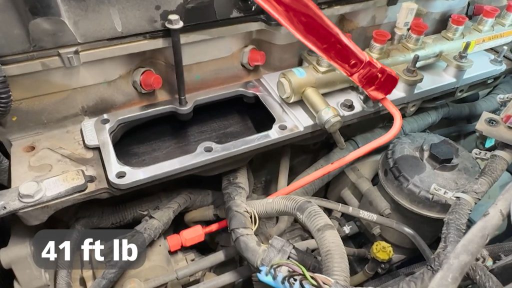
37. With a 24mm socket. Re-torque each of the 6 fuel injector tubes to 41 ft-lbs.
9. High Flow Cast Intake Plate & Fuel Rail Install
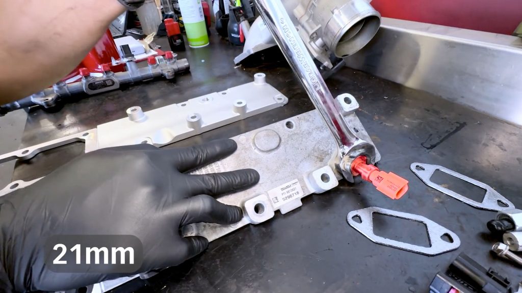
1. With a 21mm open-ended wrench, remove the temperature sensor from the factory intake manifold plate.
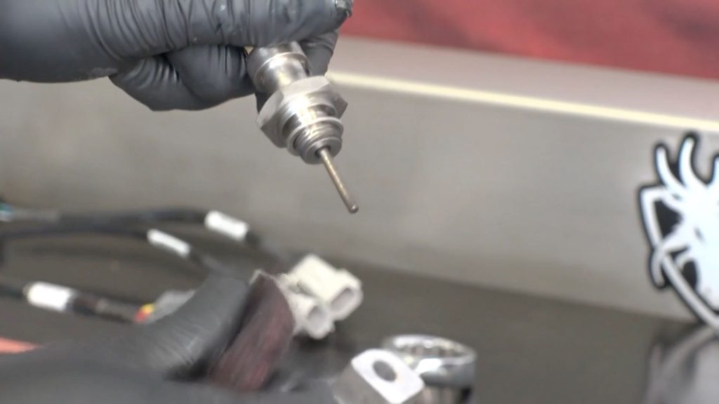
2. Now that the sensor is free, clean off any carbon buildup on the sensor probe.
3. Move the sensor to the Banks High Flow Cast Plate. Snug the sensor down, but take care not to over-tighten and damage the aluminum threads with the steel sensor.
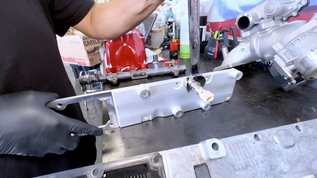
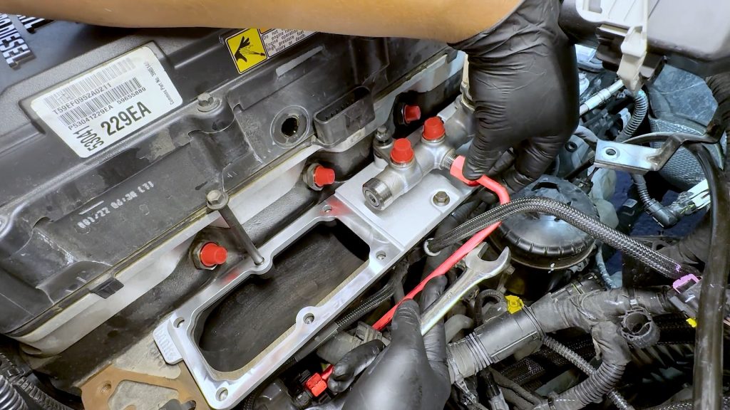
4. Bring the supplied intake manifold gasket to the engine and lay it out over each of the bolt holes.
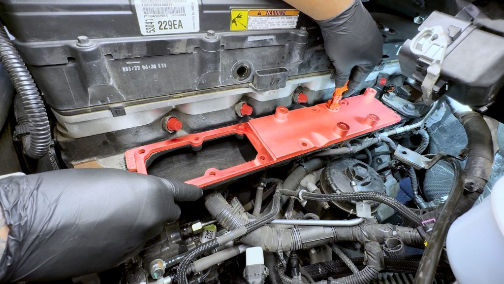
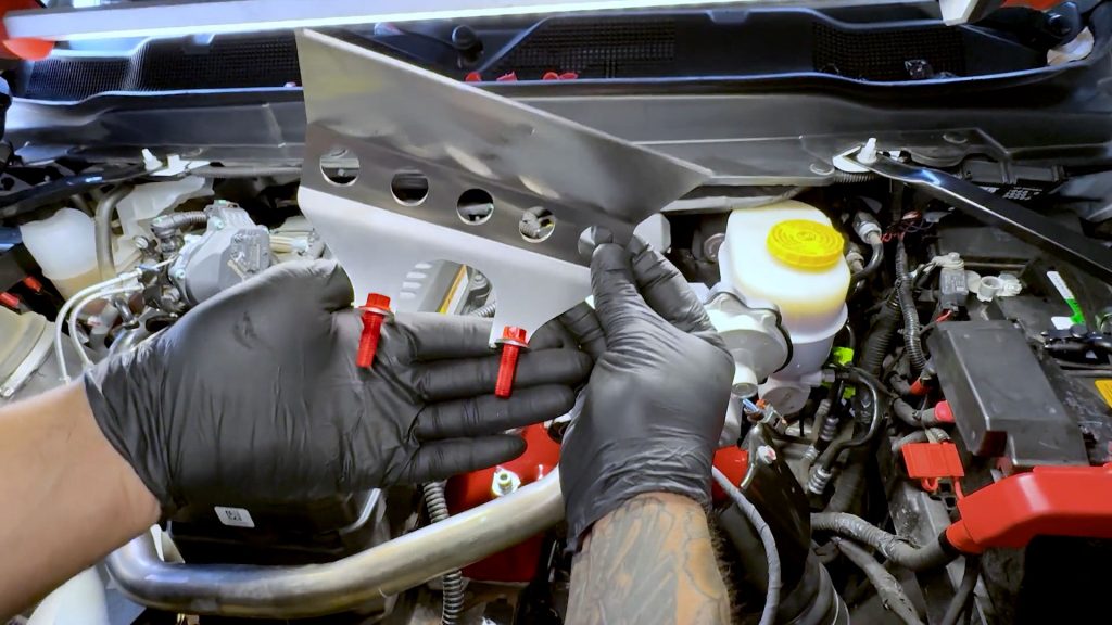
5. Bring the high-flow cast intake plate to the engine and lay it out over the gasket.
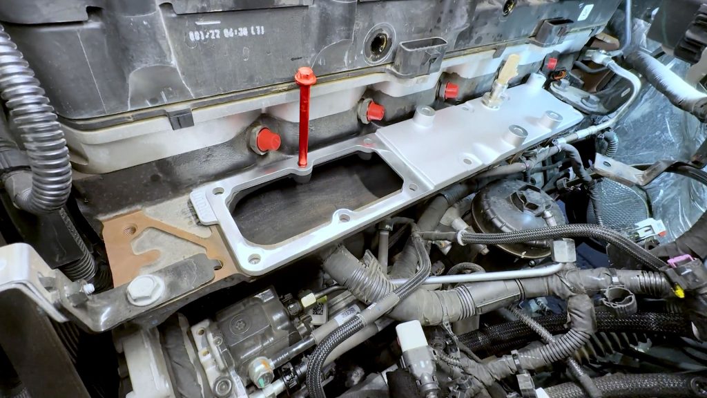
6. Use one of the bolts you removed earlier to help center the gasket and plate.
7. Grab the 4 small bolts that were removed from the factory intake plate. Apply a small dab of blue thread locker to each.
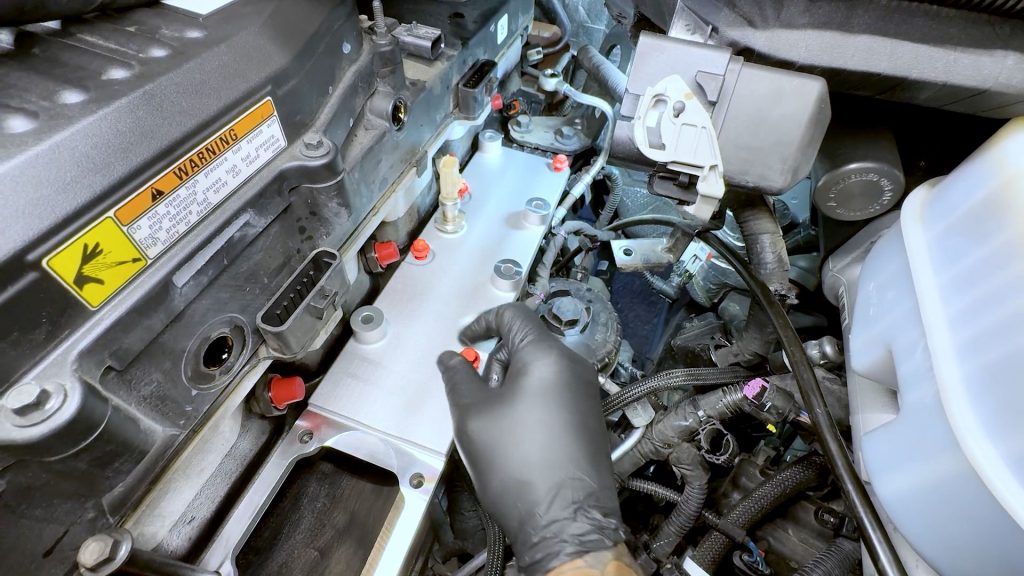
8. By hand, thread the 4 small bolts into the open spots on the high-flow plate that do not have risers.
9. Once threaded, snug the 4 bolts down. They will be torqued later.
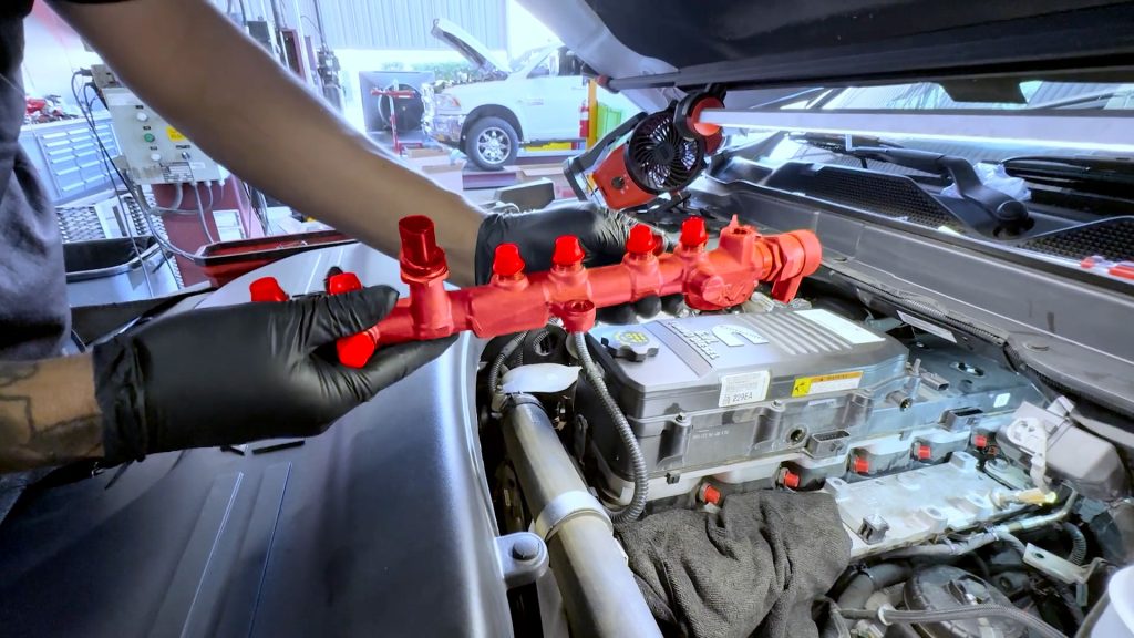
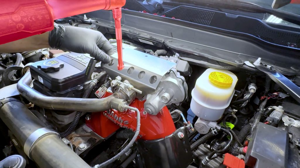
10. Bring the fuel rail back to the engine bay. Plug in and lock the sensor on the rear of the fuel rail. Lay the fuel rail on top of the risers.
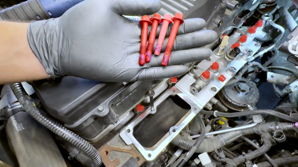
11. Grab the 4 longer bolts that were removed from the factory intake plate. Apply a small dab of blue thread locker to each.
One of the 4 bolts is shorter than the other 3.
12. By hand, thread the 3 longer bolts through the fuel rail. The shorter one goes in the remaining empty spot.
13. Grab the washer you saved from the rear banjo bolt.
14. Carefully slide the washer between the fuel rail and the rear banjo hardline.
15. Carefully thread the banjo bolt into the fuel rail by hand. This will be torqued down later.
16. By hand, thread in the hard line from the high-pressure fuel pump back into the fuel rail.
17. Tighten the hard lines with a 19mm open wrench. They will be torqued down later.
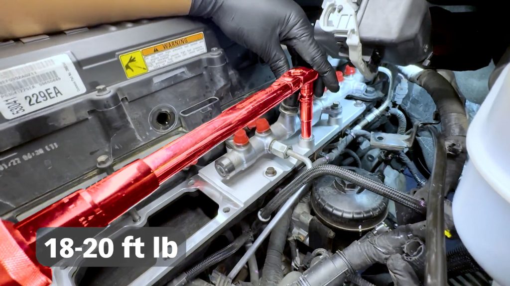
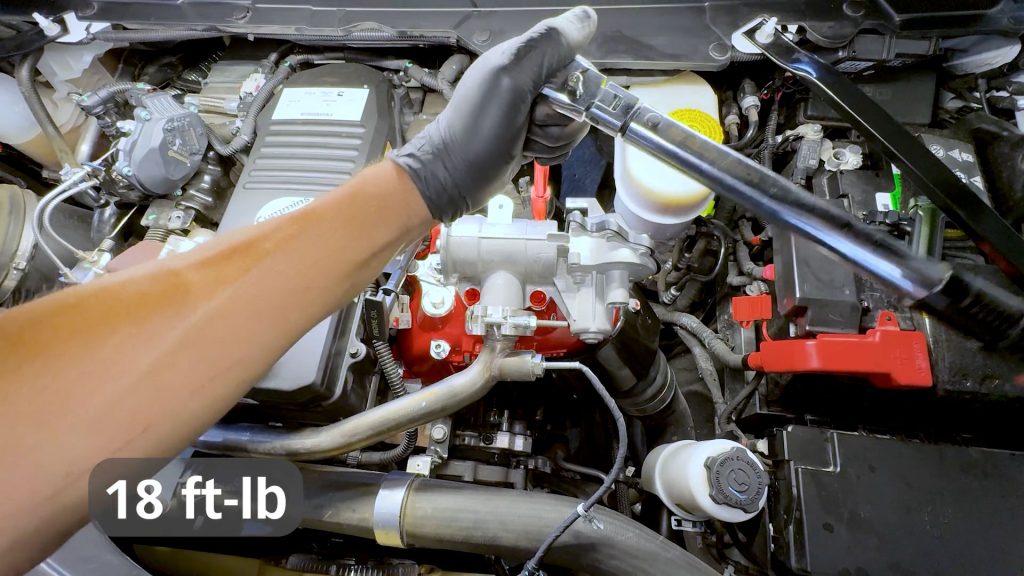
18. Torque all the 10mm bolts on the top of the high flow cast plate to 18-20 ft-lbs.
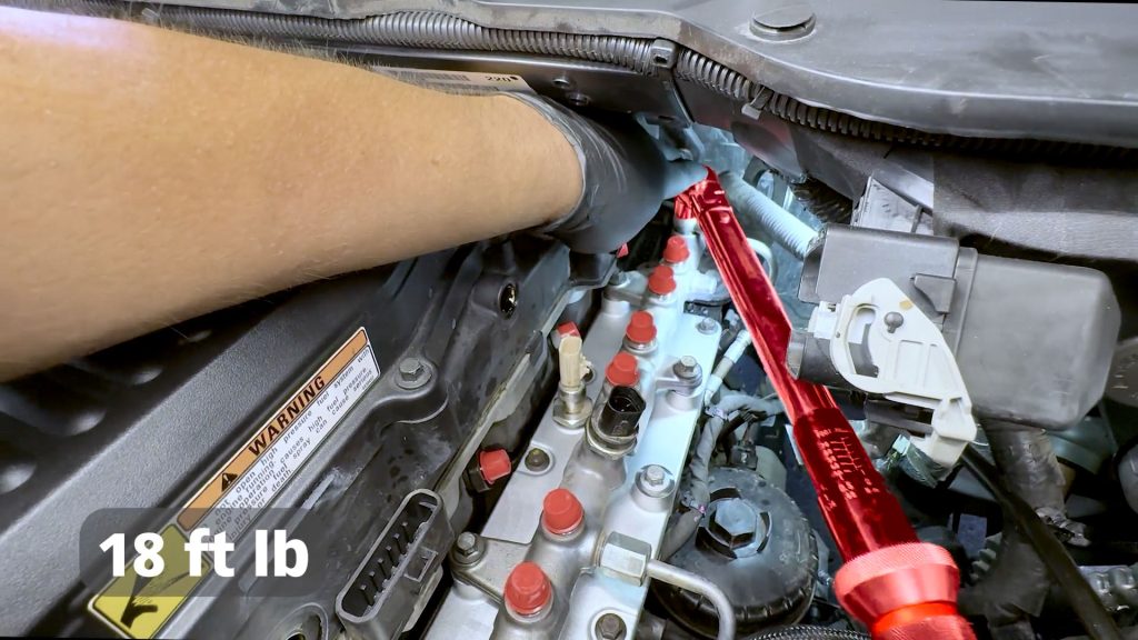
19. Torque the 17mm banjo bolt at the rear of the fuel rail to 18 ft-lbs.
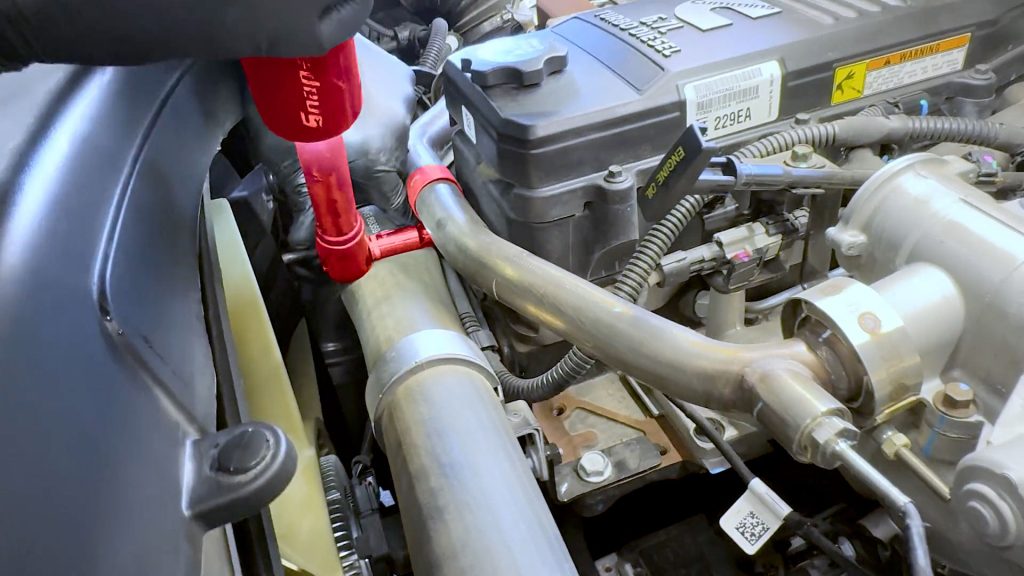
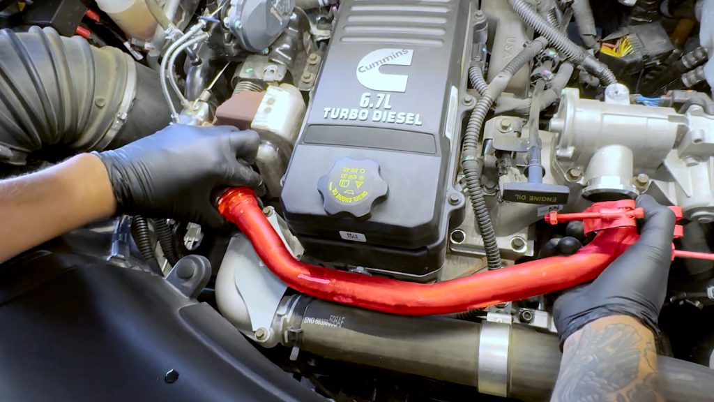
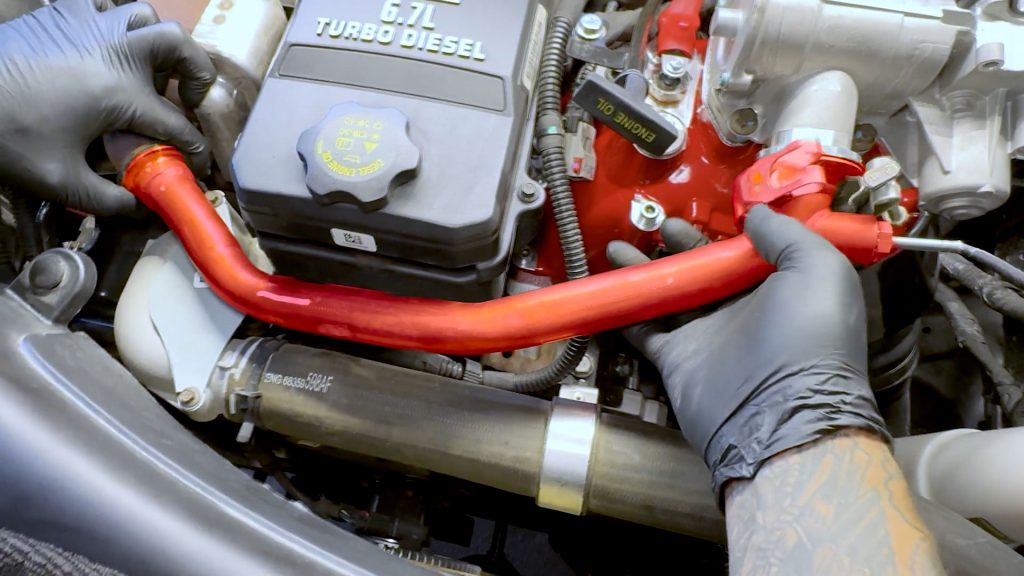
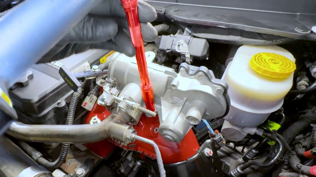
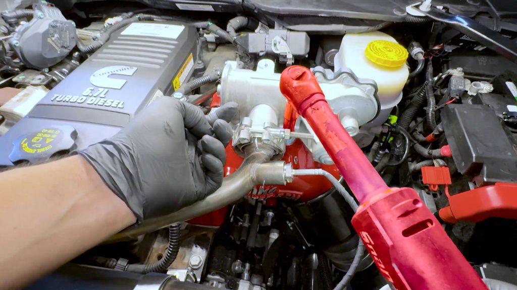
10. Fuel Line Installation
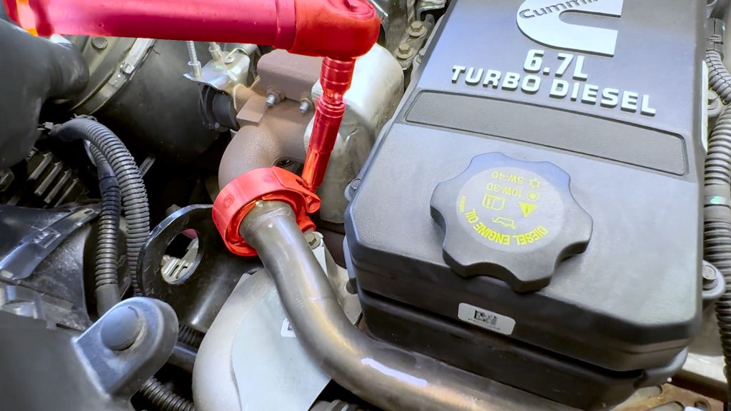
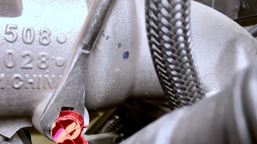
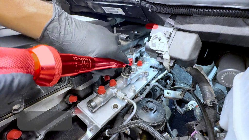
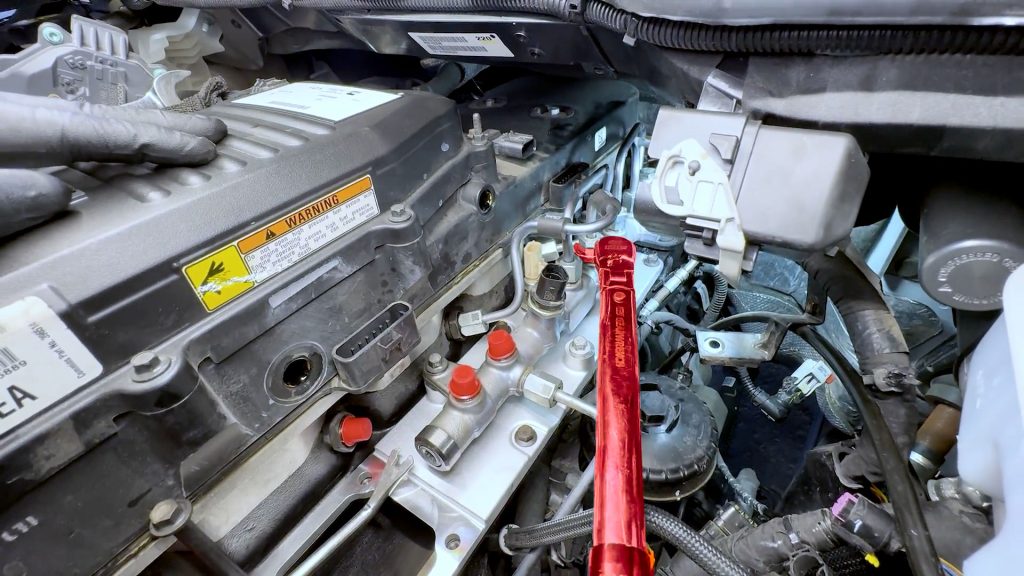
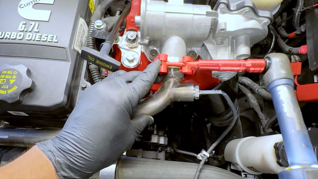
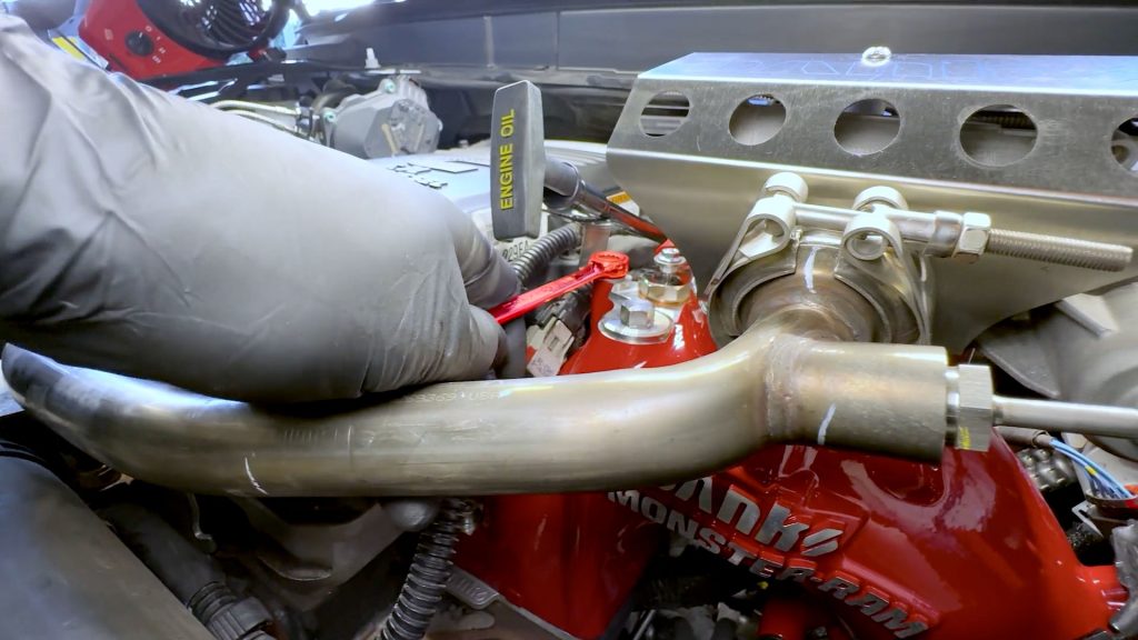
1. Start with the #6 fuel line in the back, rotate it back down onto the fuel rail, and snug it back down with a 19mm open-end wrench.
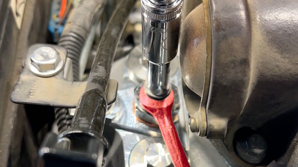
2. With your crows foot attachment, torque the #6 fuel line to the cylinder head to 41 ft-lbs.
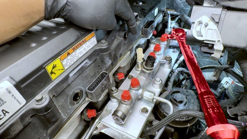
3. Do the same on the fuel rail side, 41 ft-lbs.
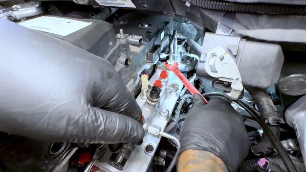
4. Next move onto the #5 fuel line. Snug the line down first with an open-ended 19mm wrench.
5. With your crows foot attachment, torque both ends of the #5 fuel line to 41 ft-lbs.
6. Next move onto the #4 fuel line. Snug the line down first with an open-ended 19mm wrench.
7. With your crows foot attachment, torque both ends of the #4 fuel line to 41 ft-lbs.
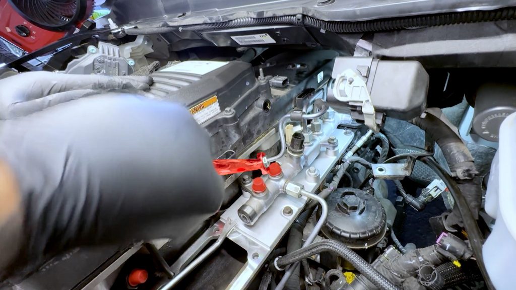
8. Next move onto the #3 fuel line. Snug the line down first with an open-ended 19mm wrench.
9. With your crows foot attachment, torque both ends of the #3 fuel line to 41 ft-lbs.
10. Next move onto the #2 fuel line. Snug the line down first with an open-ended 19mm wrench.
11. With your crows foot attachment, torque both ends of the #2 fuel line to 41 ft-lbs.
12. Don’t forget to torque the top and bottom of the fuel line from the high-pressure fuel pump to 41 ft-lbs.
13. Remove the factory bolt you had in place to hold the plate.
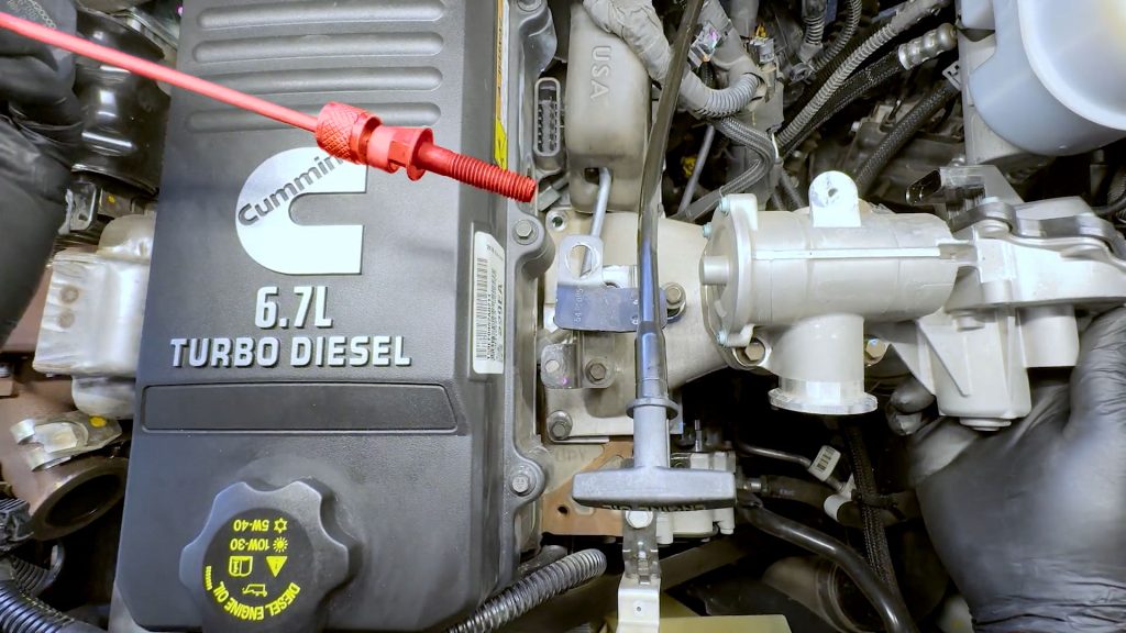
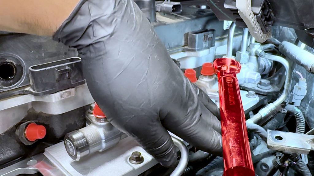
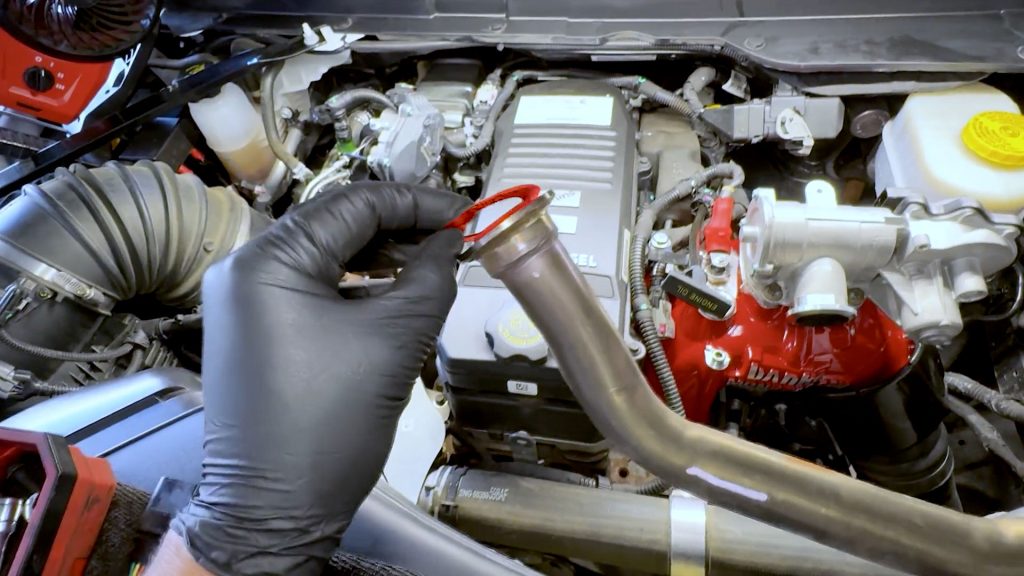
14. Lastly, move on to the #1 fuel line with the new Banks fuel line. Snug the line down first with an open-ended 19mm wrench.
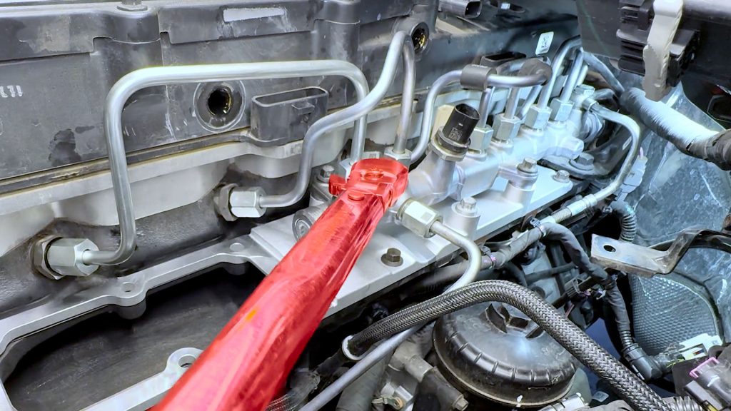
15. With your crows foot attachment, torque both ends of the #1 fuel line to 41 ft-lbs.
11. Sensors, Harness, and Dipstick.
1. Now that the fuel system is fully installed and torqued. Remove the driver’s side stud from the fuel rail.
2. Free the dipstick tube from the bungee cord that was holding it off to the side.
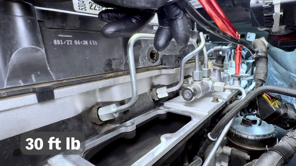
3. Slide the dip-stick tube back over the stud and torque it down to 30 ft-lbs.
4. Plug in the supplied Banks extension harness for the temperature sensor on the high-flow cast intake plate.
5. Connect the other end to the factory harness.
6. Secure the harness with the factory cable tie clip.
7. Replace the rubber fuel rail isolator you removed earlier.
8. By hand, thread the front and rear plastic PCV barbs back into the valve cover.
9. Snug them both down with a 19mm open-ended wrench.
10. Slide the rear PCV hose onto the rear barb.
11. Route the factory engine harness under the dipstick and back around behind the engine valve cover.
12. Plug in the blue injector plug at the rear of the cylinder head.
13. Plug in the rear white plug at the rear of the cylinder head.
14. Plug the sensor on the fuel rail back in.
Be sure to slide the locking tab back in place.
15. Route the harness back around the rear of the engine, placing the cable ties back on the rear studs.
Cable tie number 2.

Cable tie number 3.
16. Reconnect and lock the plug to the EGR cooler valve actuator.
17. Reconnect the plug to the passenger side of the EGR Actuator.
18. Reconnect and lock the sensor on the rear passenger side of the valve cover.
19. Reconnect the large data cable on the driver’s side, and swing the lever back into the locked position.
20. Secure the harness with its plastic cable tie back into its mount.
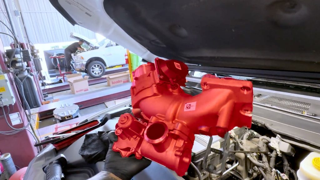
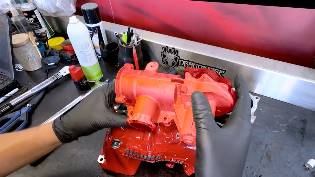
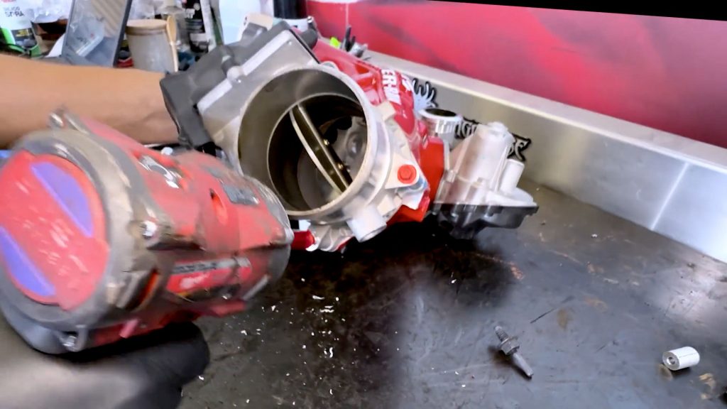
12. Monster-Ram Prep and Assembly
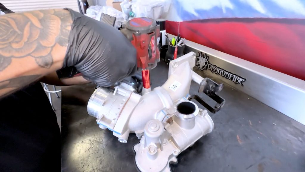
1. Back at the workbench, remove the stud from the front of the factory intake elbow. It will be transferred over to the Monster-Ram later.
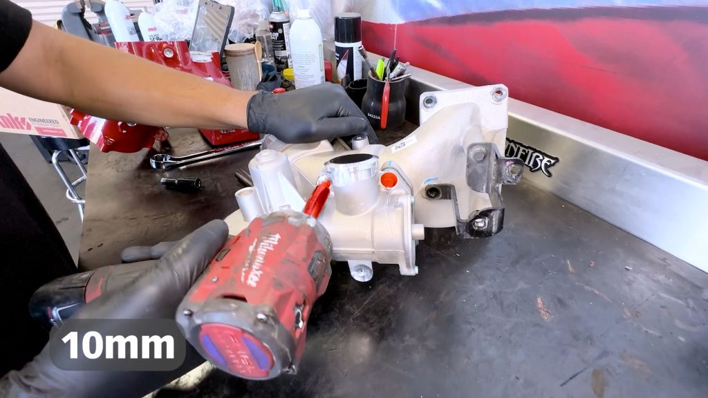
2. Remove the 4 bolts that hold the EGR valve; these will be transferred over to the Mosnter-Ram later.
3. Remove the 4 bolts that hold the throttle valve; these will be transferred over to the Mosnter-Ram later.
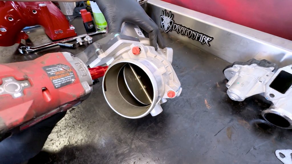
4. Remove the throttle assembly from the intake elbow, and set it aside.
5. Remove the MAP sensor from the side of the factory intake elbow and set it aside.
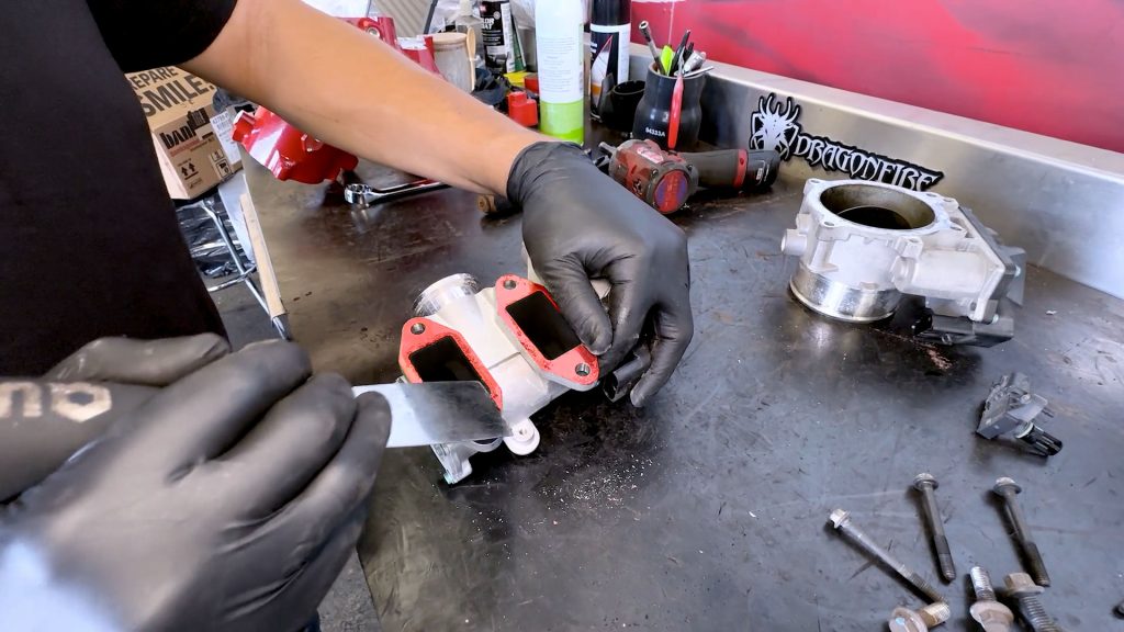
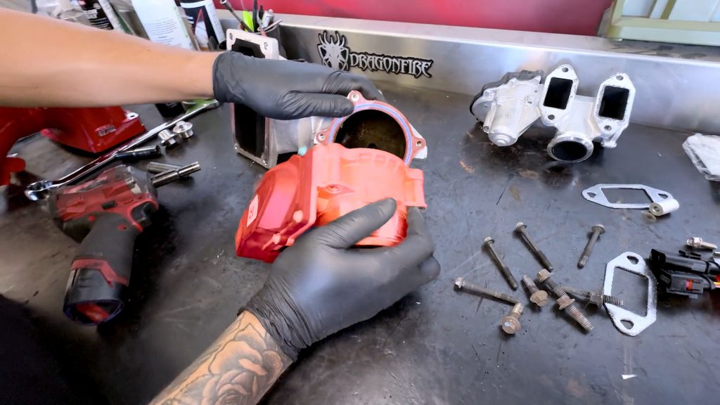
6. Clean any old gasket material off the underside of the EGR valve.
7. Clean any old gasket material off the underside of the throttle valve.
8. Some compressed air can help blow away any loose debris.
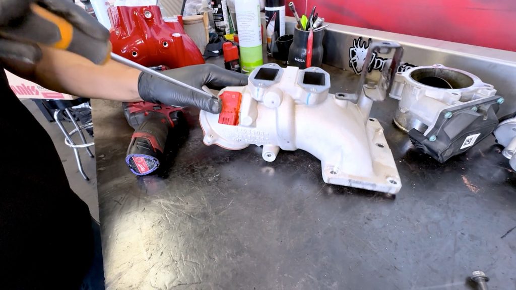
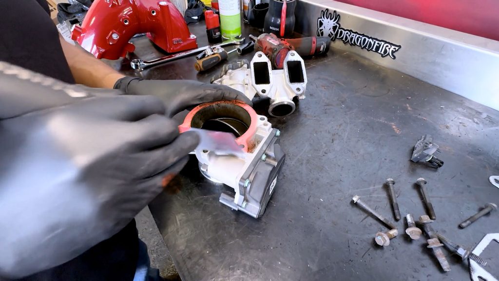
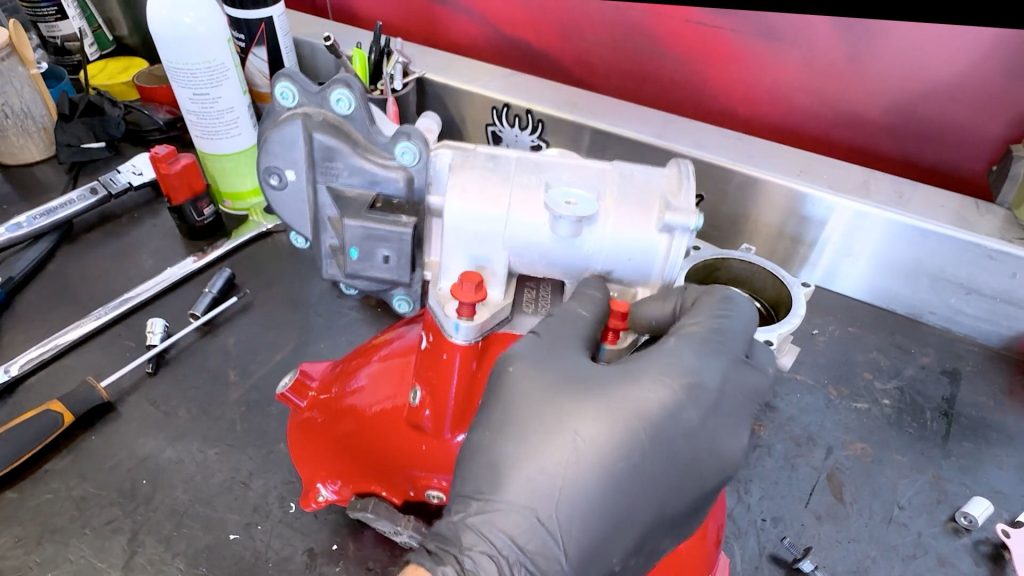
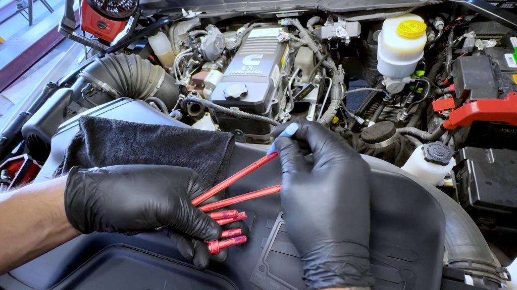
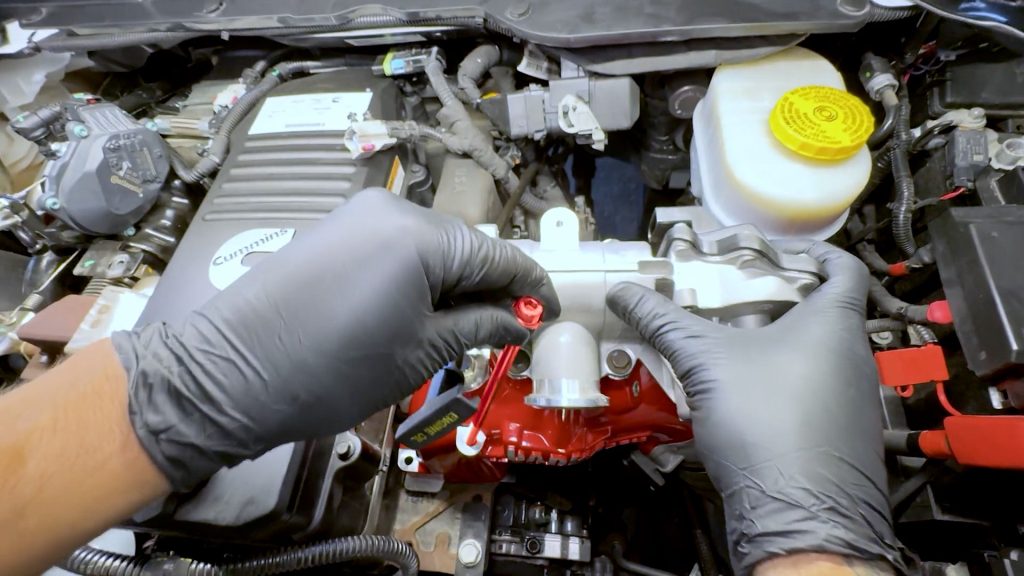
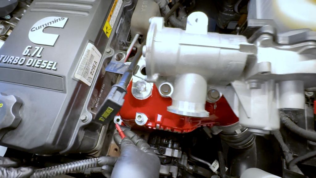
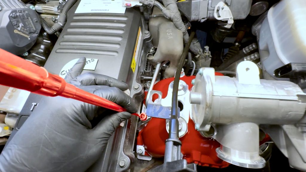
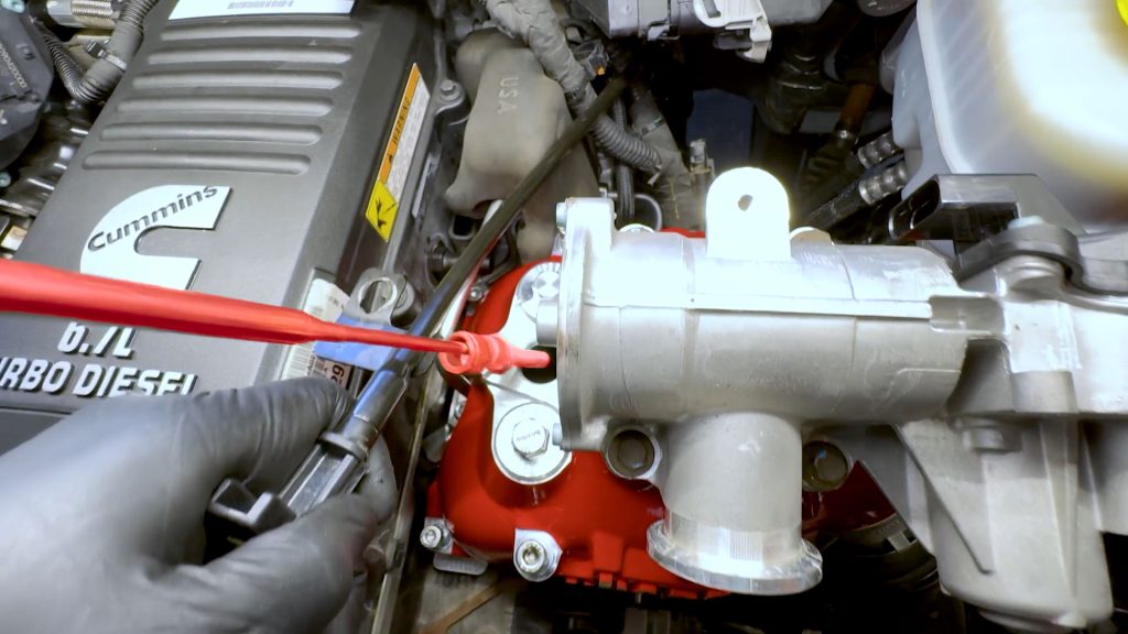
9. Locate the 4 1/8″ NPT plugs.
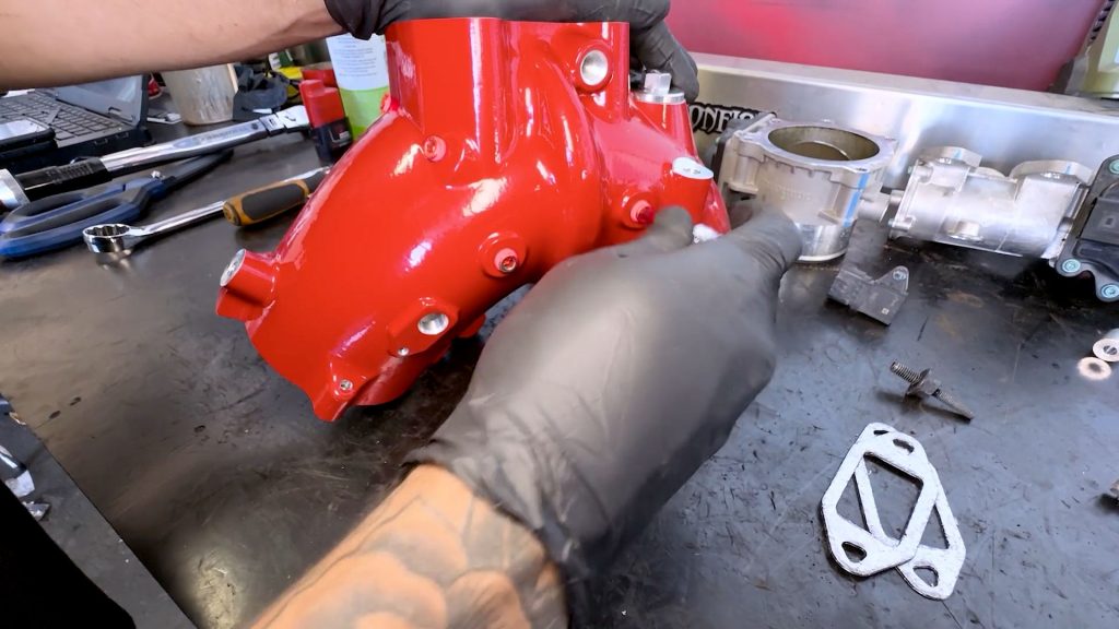
10. Thread them in by hand; they should feel snug, but don’t over-tighten them.
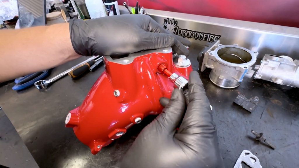
11. Thread the larger hex plug into the port around the EGR ring with a 360° bead of blue Loctite around the leading threads first. Keep going until this one bottoms out.
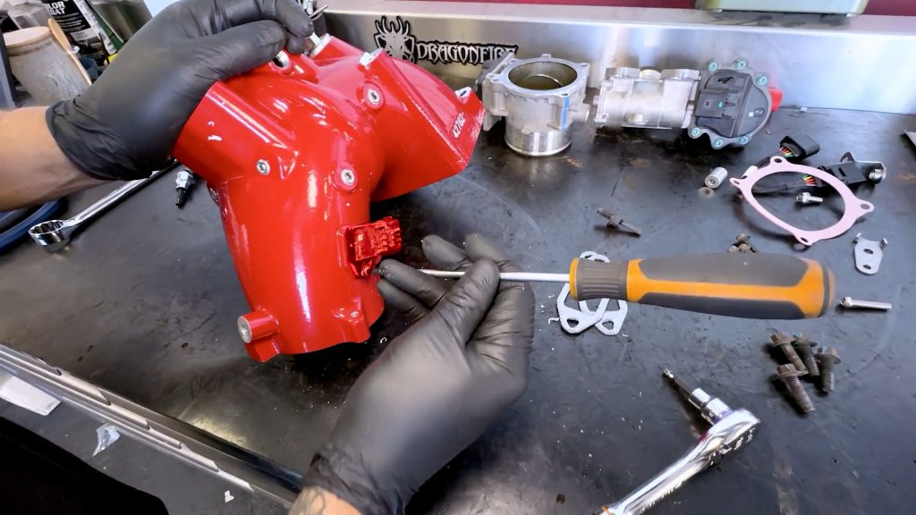
12. Transfer the MAP sensor onto the Monster-Ram.
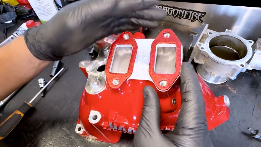
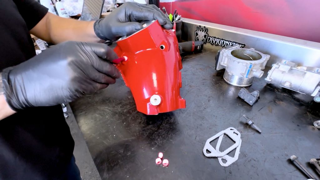
13. Place the two new EGR gaskets on top of the Monster-Ram.
14. Place the EGR valve on top with the inlet facing towards the Monster-Ram logo, and plug on the back side.
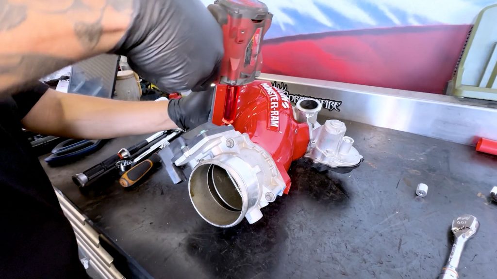
15. Thread in the four 10mm bolts that secure the EGR valve by hand.
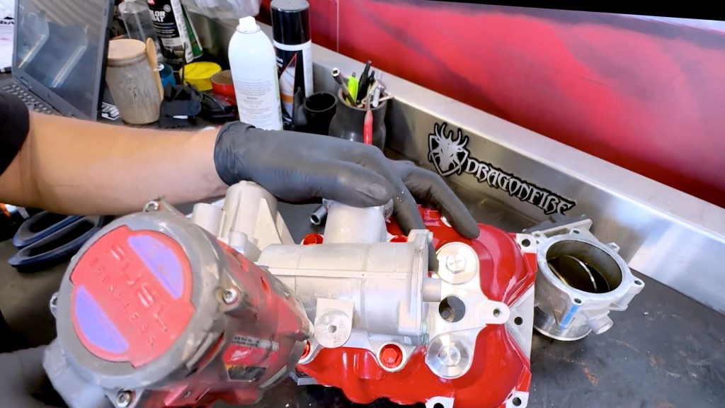
16. Snug them down for now; they will be torqued later.
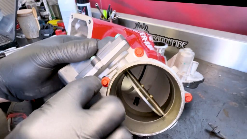
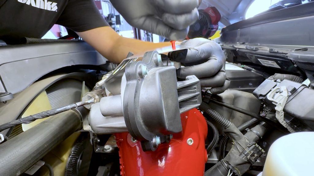
17. Thread in the four bolts that secure the throttle valve to the Monster-Ram.
18. Snug the four bolts down.
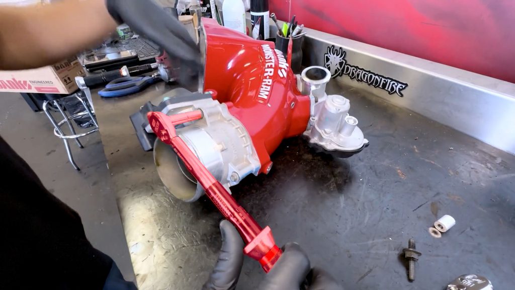
19. Then torque them to 7.5 ft lb (89 in-lb).
20. Reinstall the stud on the front-facing side of the Monster-Ram that was removed earlier from the factory intake elbow.
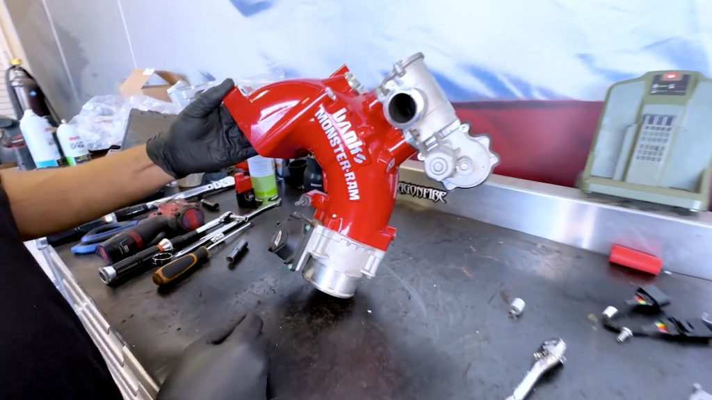
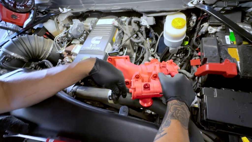
21. Grab the whole assembly and bring it back to the truck.
13. Monster-Ram Installation
1. Slide a washer on each of the 4 longer Monster-Ram bolts, and put some blue thread locker on each.
The two shorter screws will already have a flanged head on them.
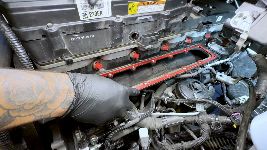
2. Set down the provided gasket for the Monster-Ram.
3. Remove the rag from the factory boost tube outlet, and put the spring clamp back around it.
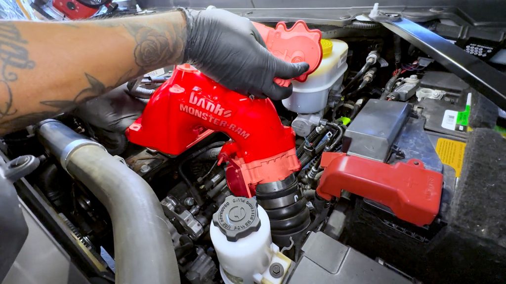
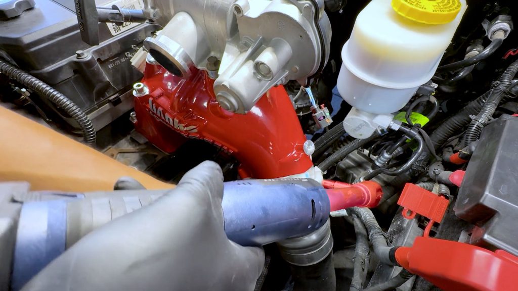
4. Bring the Monster-Ram over to the engine bay. Slip the throttle valve into the boost tube first, then line up the six holes over the gasket.
5. Start with the two longest Monster-Ram bolts, thread them in by hand.
6. Then thread in the smaller two towards the cylinder head.
7. Use a magnet tool for the last two difficult bolts, starting with the one towards the front.
8. Take extra care when installing the last bolt. Once inside, give it a few turns to engage the threads.
9. Use the provided hex extension to fully seat each bolt..
10. Then torque each of the 6 bolts to 18-20 ft lb.
14. Engine Harness and Sensors
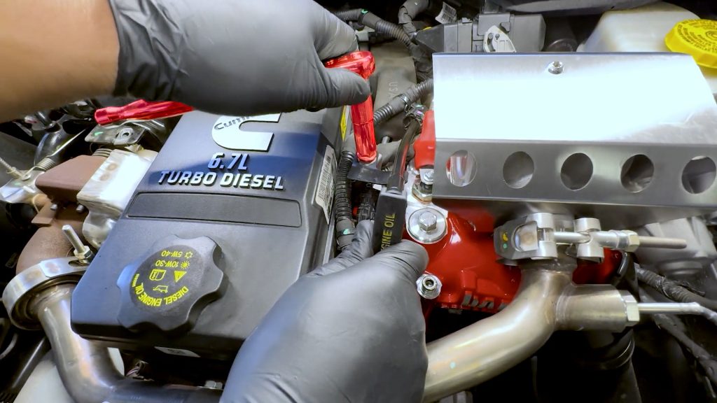
1. Work the front PCV hose back onto the barb next to the Monster-Ram. It’s a tight fit, so take your time until the hose is fully seated.
2. Reconnect the forward blue/green injector plug.
3. Connect the MAP sensor to the factory harness on the back side of the Monster-Ram.
4. Reconnect the throttle to the factory harness.
This is a blind reach and is located on the rear underside of the Monster-Ram.
5. Snug down the clamp on the factory boost tube to the throttle body.
6. Reinstall the heat shield around the throttle valve and snug down its two bolts.
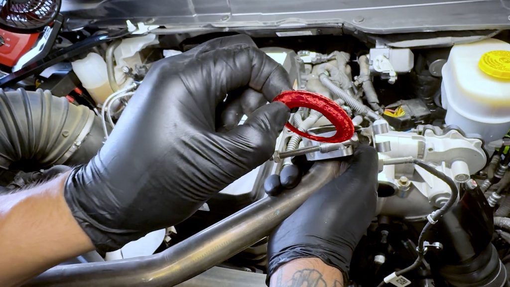
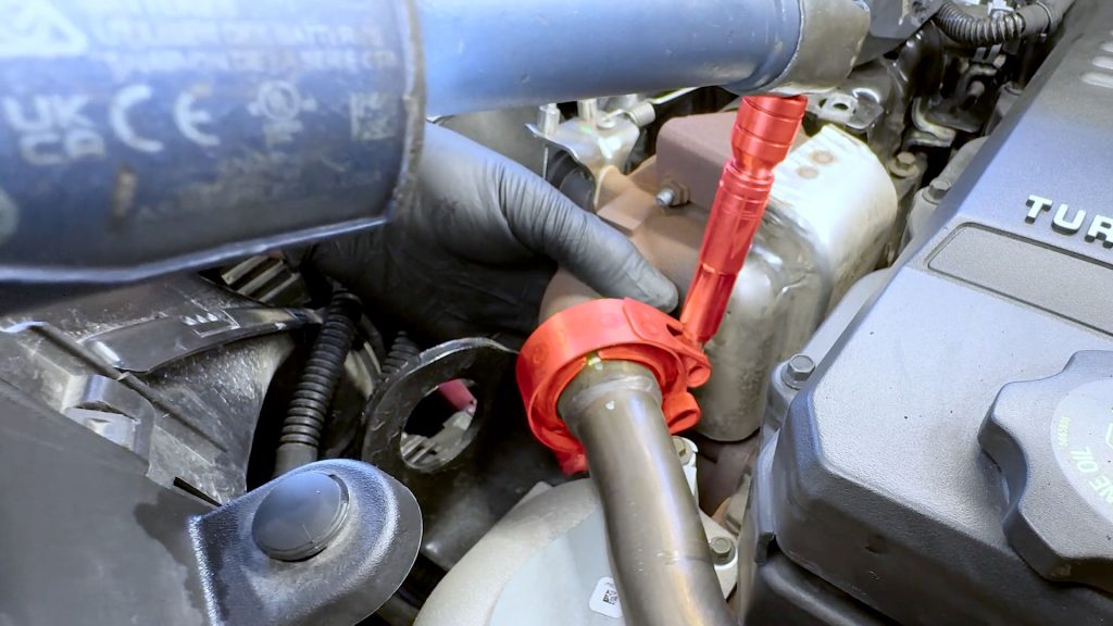
15. Coil Heater Installation
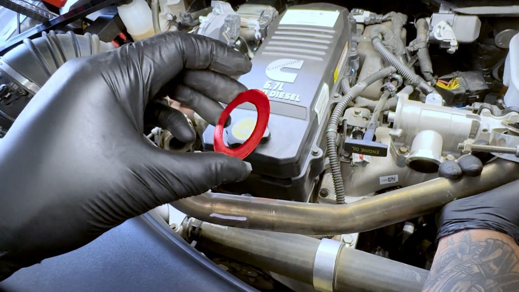
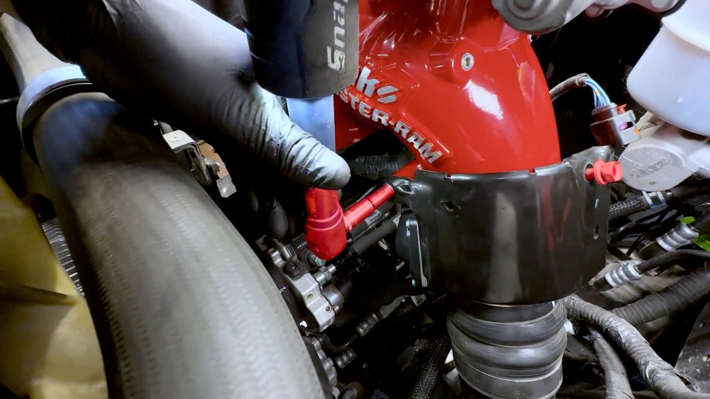
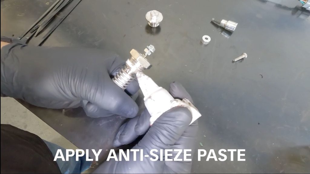
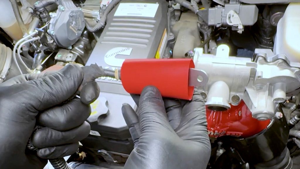
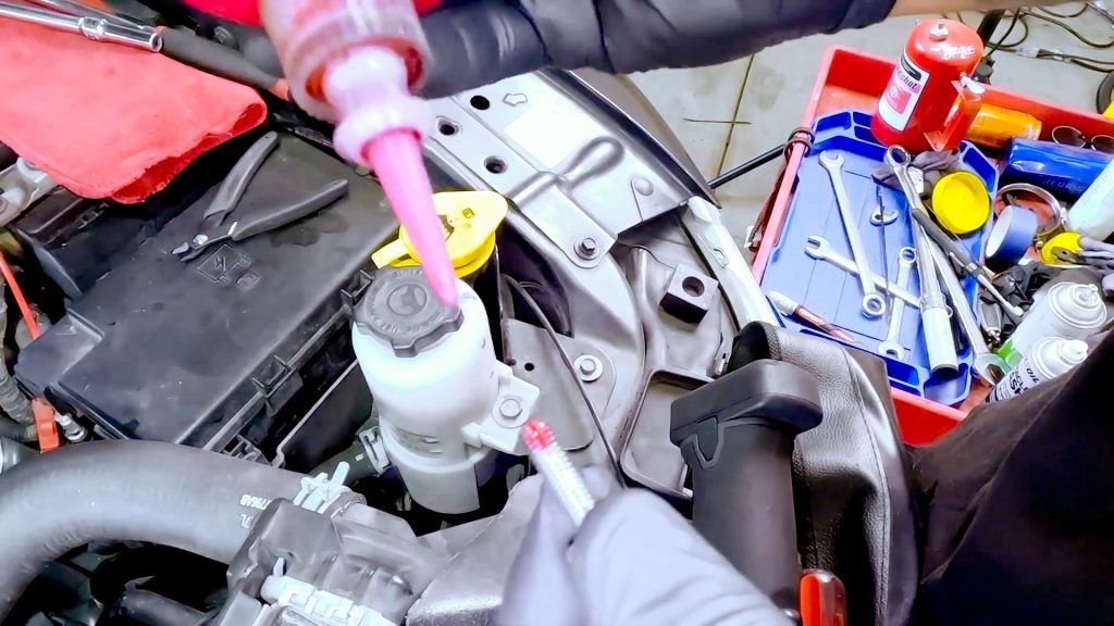
1. Start by adding a bit of anti-seize to the threads of the coil heater.
2. Slide the copper washer onto the coil heater.
3. Start the coil heater threads by hand, then snug it down with a 19mm wrench.
Do not use a socket as it could easily over-torque the coil.
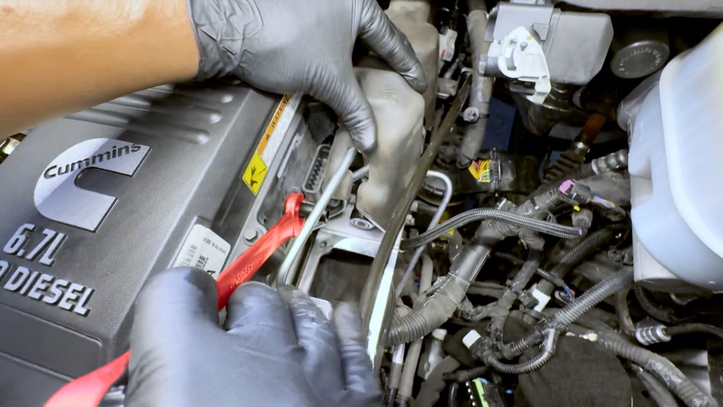
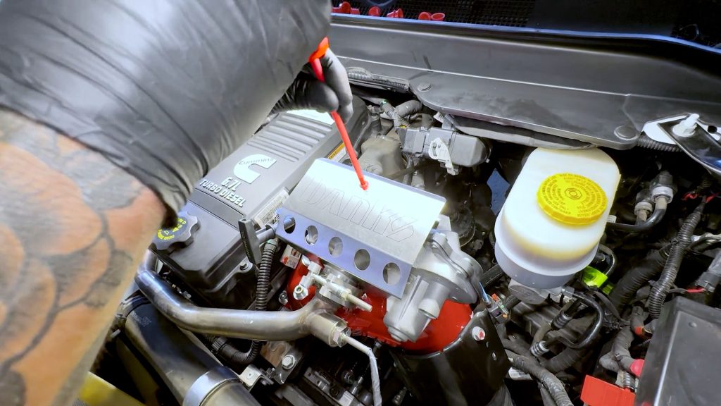
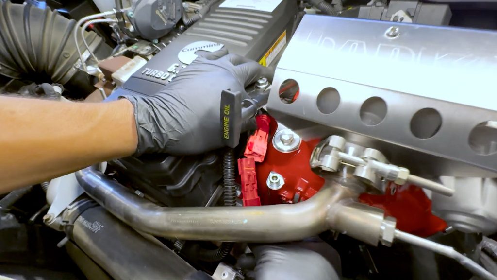
4. Grab the dipstick relocating bracket and bolt. and install it on top of the Monster-Ram
Reinstall the dipstick tube onto the new bracket with the supplied bolt.
5. Re-attach the wire harness cable tie to the dipstick tube.
The following step for the heater coil is critical.
6. Remove the lower nut from the heater coil, and apply a drop of blue thread lock to the threads.
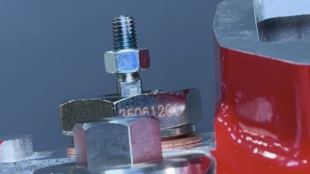
Replace the lower nut back onto the heater coil. Be sure the leave 1-2 threads visible under the nut.
You want to make sure the 12V heater cable does not come into contact with the rim of the heater coil.
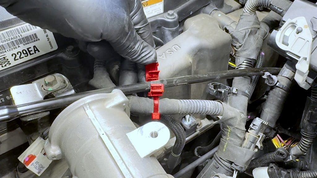
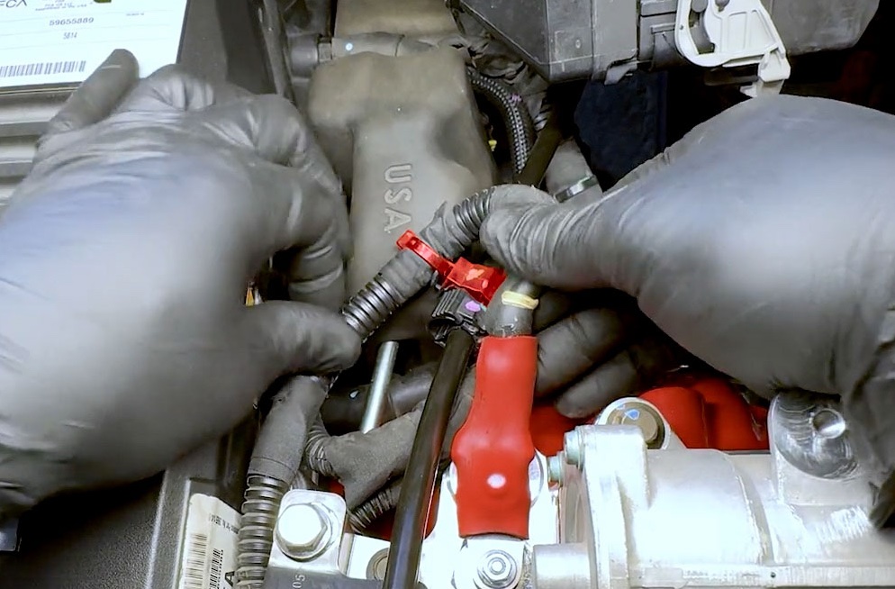
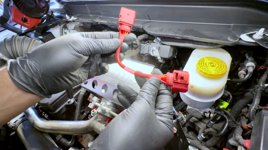
7. Take the 12V power lead for the heater and line it up it with the coil heater adapter.
8. Thread the supplied bolt into the captive nut on the 12V power lead.
9. Snug the nut and bolt together.
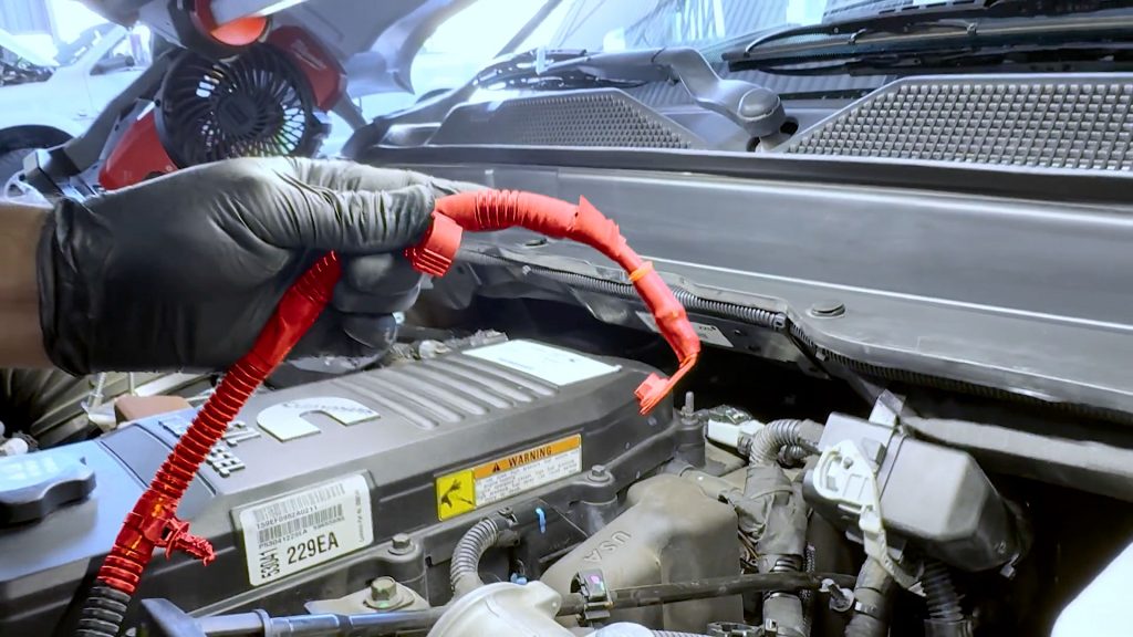
10. Slide the heat shrink tubing over the union, taking care to fully cover the nut and bolt.
11. With a heat gun, carefully apply heat from all sides to shrink the tubing and activate the adhesive.
The heat shrink is thick and will take some time to fully reduce. Take care not to burn your hand as the heat from the heat gun will transfer through the wire.
The 12V wire will remain hot for some time after the heat shrink is reduced. Take care when handling it.
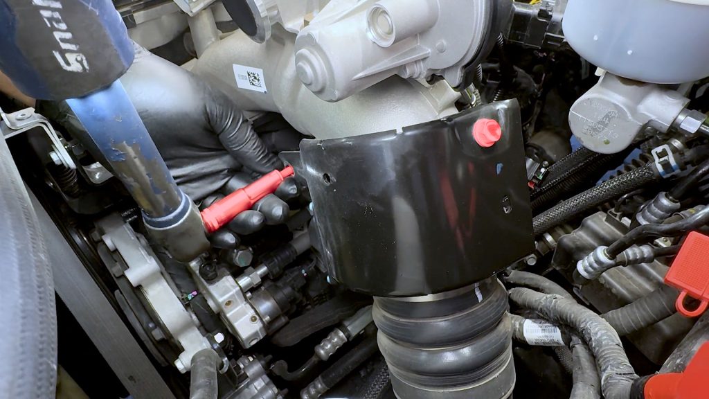
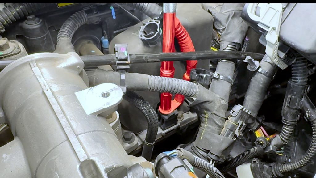
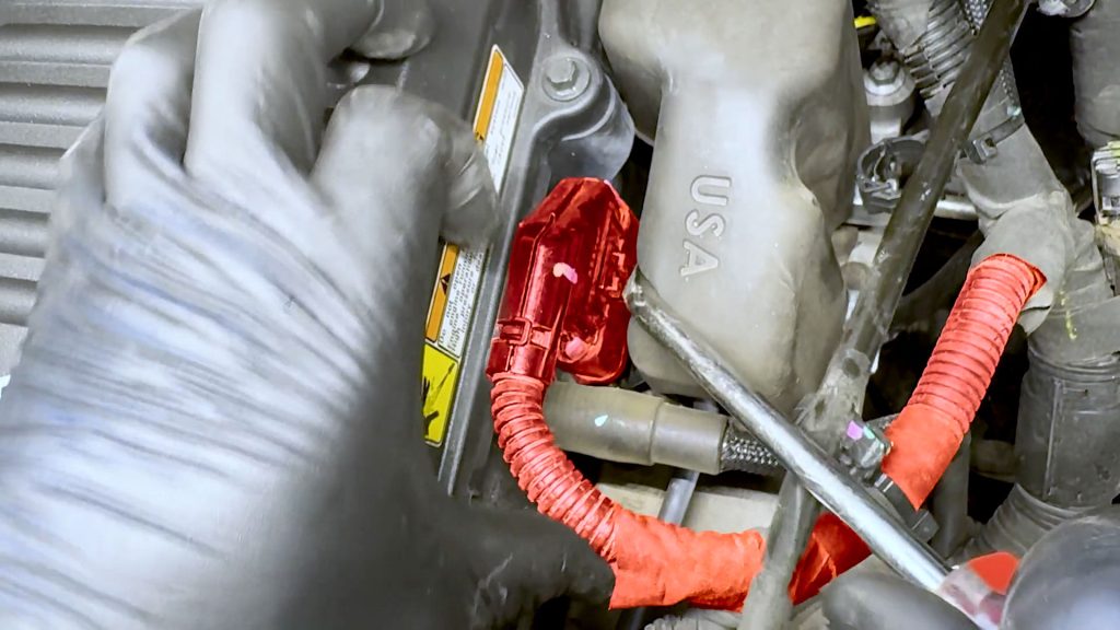
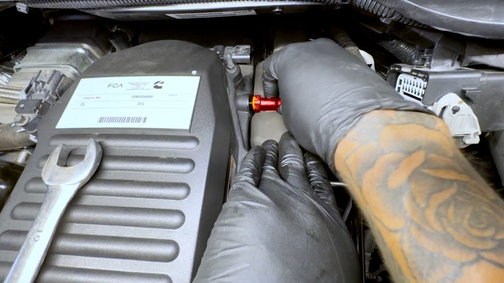
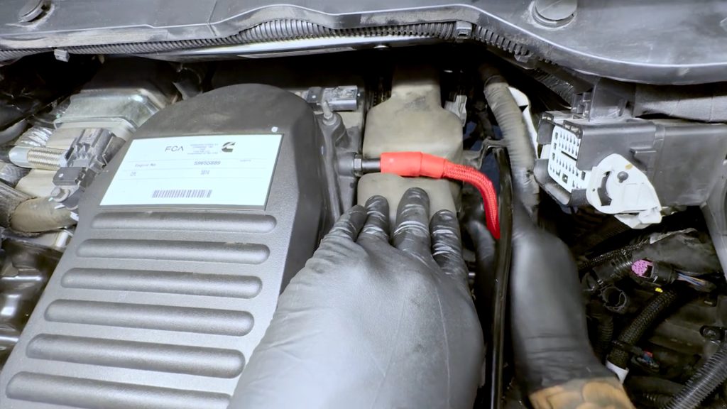
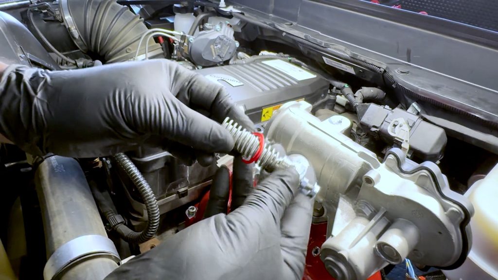
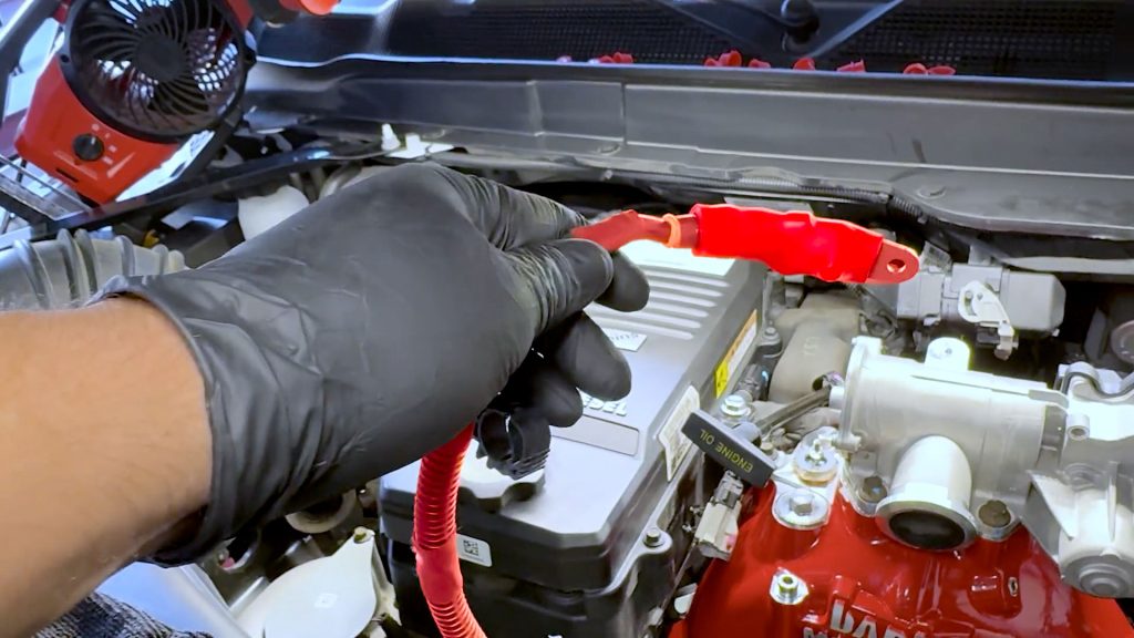
12. Line up the 12V power lead on top of the coil heater.
The following step is critical. Failure to do so can break the internal insulated post free from the rest of the coil and damage the heating element.
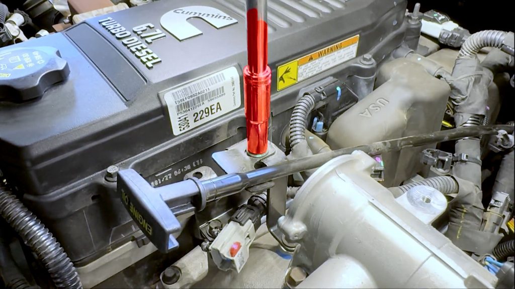
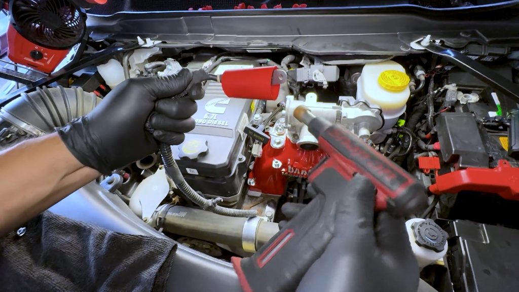
13. When tightening the top nut of the heater coil, you must also place a crescent wrench on the lower nut so that it does not move.
You want to cinch the two nuts together and sandwich the 12V adapter.
Do not just thread the top nut onto the adapter plate.
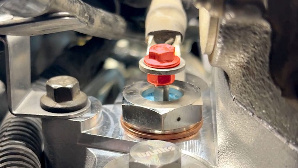
If done correctly, the 12V heater wire and adapter plate should look like this.
14. Secure the 12V wire’s cable tie to the dipstick tube.
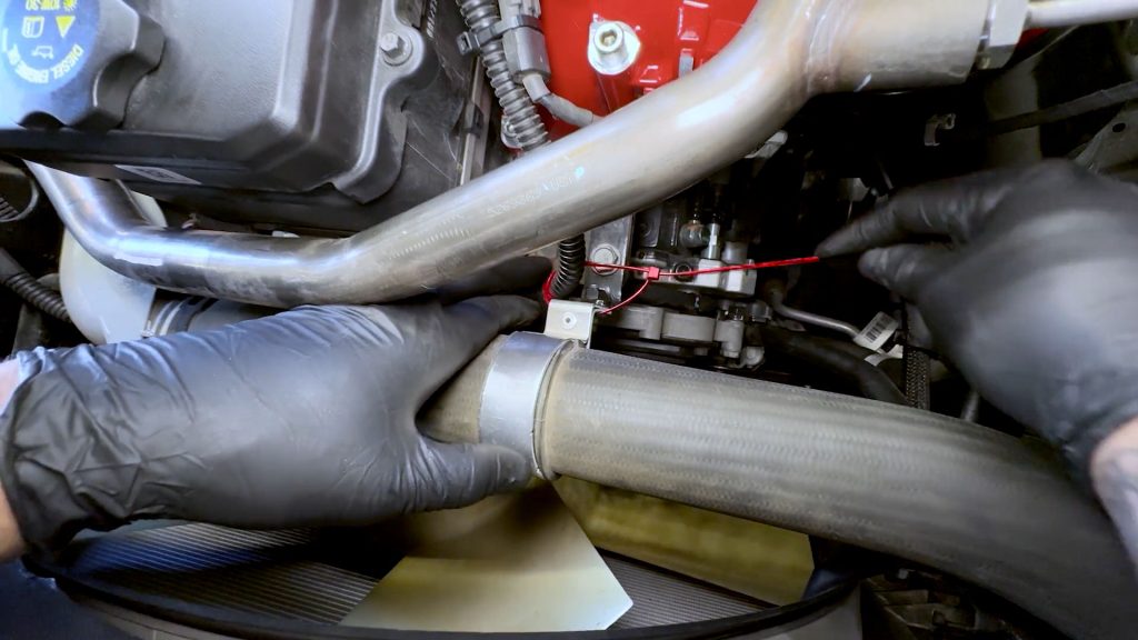
16. EGR Crossover Tube Reinstallation
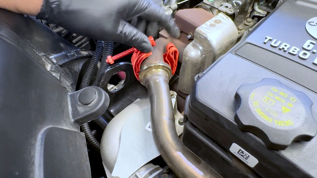
1. Start by flipping the driver’s side clamp over so that it can be tightened from the right side. This makes it easier to access the nut with a socket when tightening the clamp.
2. Remember, the conical gasket goes on the driver side of the EGR crossover tube. Place it onto the tube, and hold it in place with your right hand.
3. And, the flat gasket goes on the passenger side of the EGR crossover tube.
4. Taking care not to lose the two gaskets, line the EGR crossover tube to the EGR cooler and EGR valve.
5. Slide the passenger side clamp back over the EGR tube first so the gasket wont fall, and start tightening it by hand.
6. Then, continue tightening the driver’s side clamp.
7. Finish tightening the passenger side clamp.
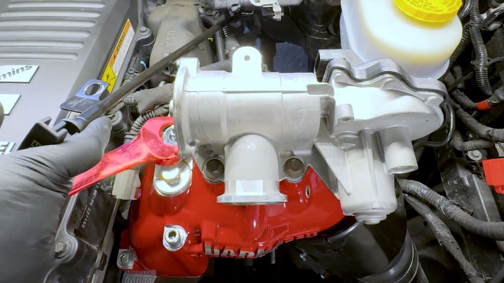
17. EGR Valve Heat Shield
1. Snug down the 4 bolts that old the EGR valve onto the Monster-Ram.
2. Torque the bolts down to 18 ft lbs to make sure the valve is seated properly on its gaskets.
3. Then remove the front two bolts.
4. Slide the two bolts into the EGR valve heat shield.
5. Then retighten and torque the front two bolts.
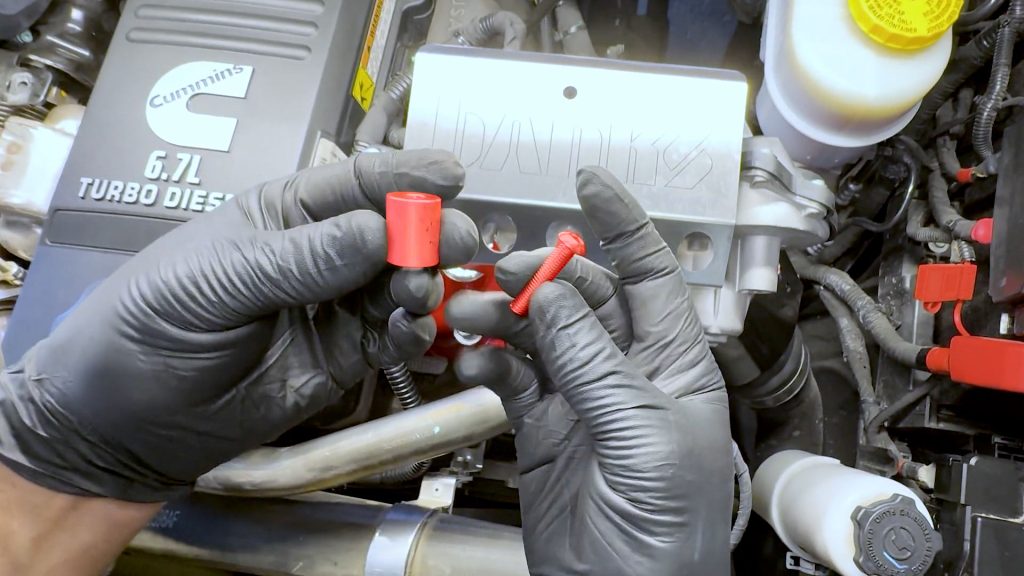
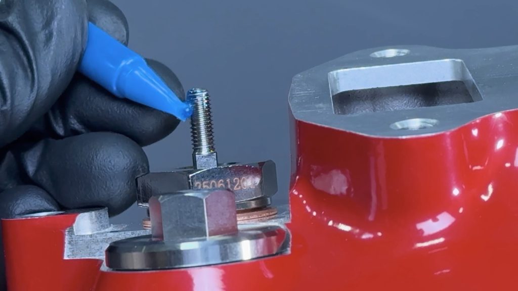
6. Grab the aluminum spacer and sc rew for the EGR heat shield.
7. Place a drop of thread locker onto the screw.
8. Thread the screw into the Monster-Ram through the top of the EGR heat shield and spacer.
9. Tighten the screw.
10. Check that the dip stick bracket bolts are secure.
11. Check that the dip stick bracket bolts are secure.
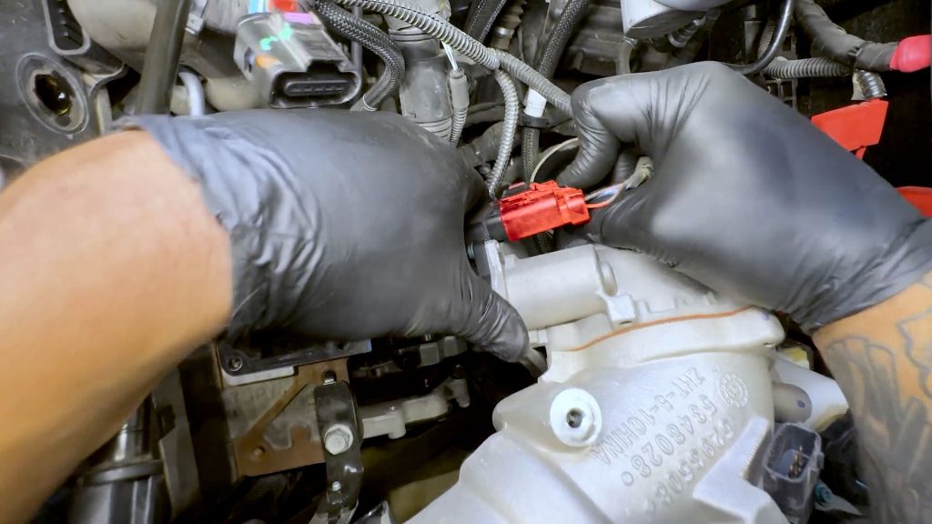
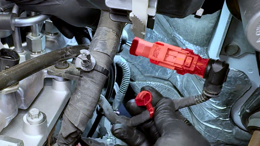
12. Grab the supplied EGR valve extension harness.
13. Plug the extension harness into the EGR valve…
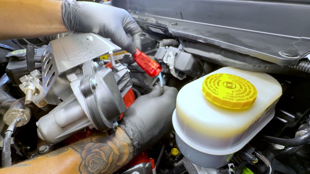
… and the other end into the factory engine harness.
14. Connect the EGR temperature sensor into the factory harness. Be sure to slide the red locking tab back to the locked position.
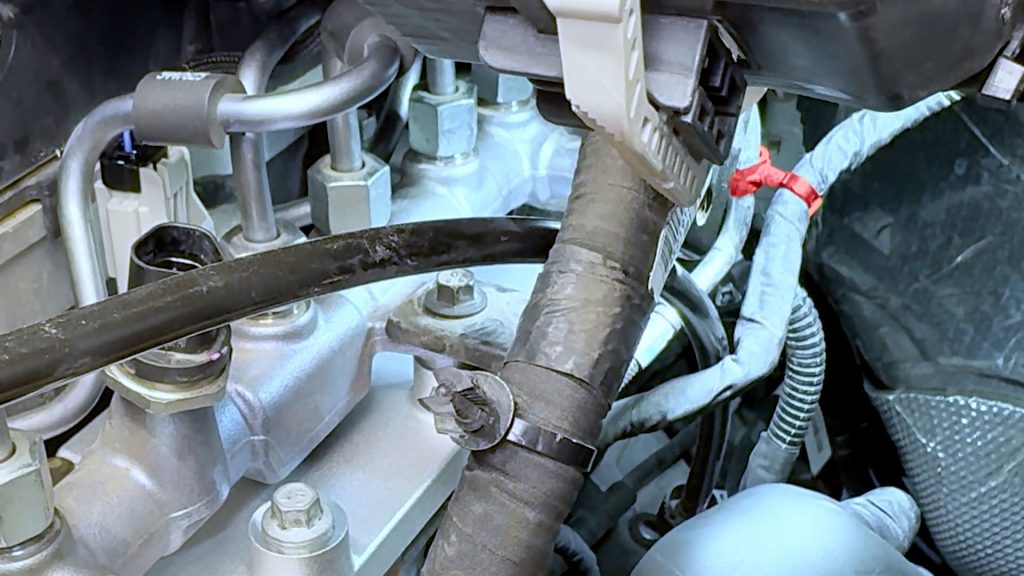
15. Reattach the EGR temperature sensor cable, which was tied back into the throttle heat shield.
16. Secure any loose harnesses with a zip tie.
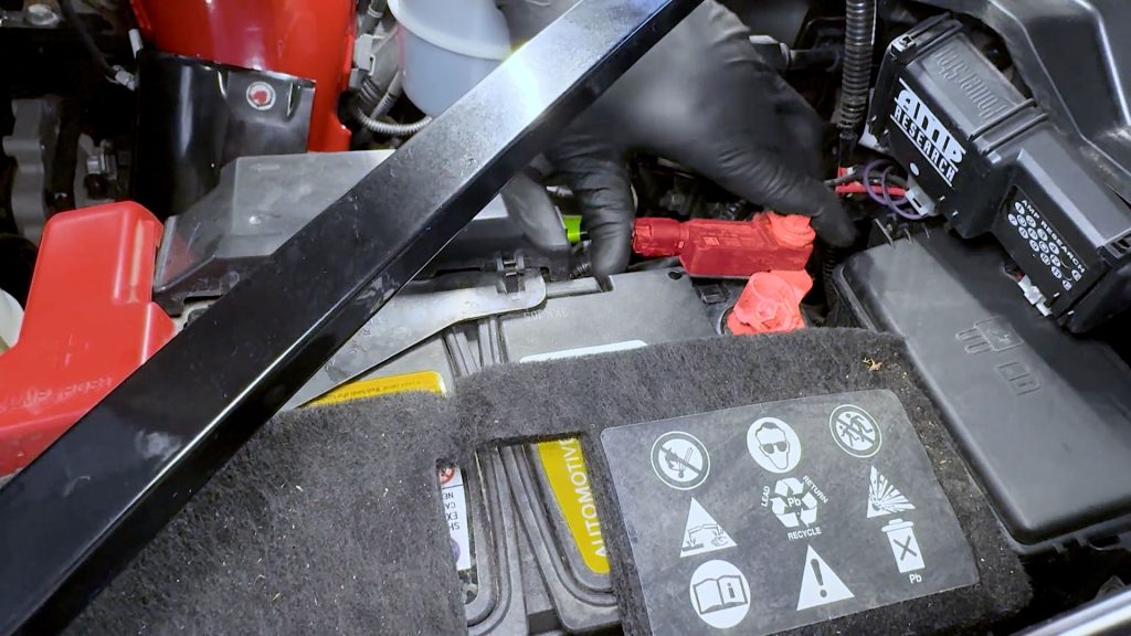
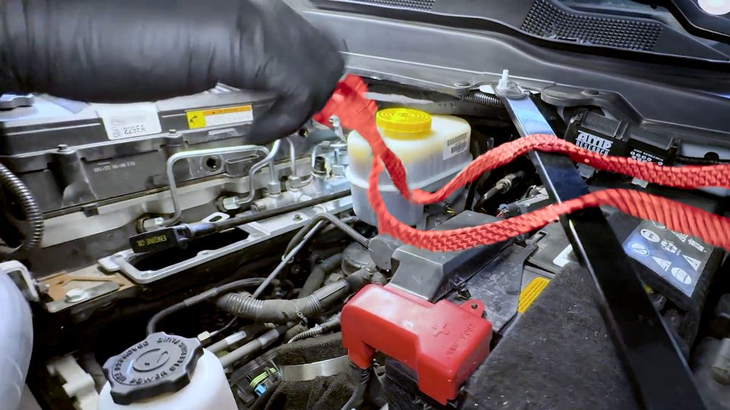
17. Reconnect the driver’s side battery.
18. Reconnect the passenger side battery.
First start may take 1-2min of engine turnover.
This is normal. The fuel system, rail, and fuel lines need to be re-pressurized after installation.
Check for leaks.
Check that all harnesses and components are free of moving parts. Check for any leaks while the engine is running.
Head out for a short test drive, then double-check for leaks one last time.

CARB EO Label
For smog check purposes, affix the CARB E.O. Label on a visible location under the hood. Banks recommends using the radiator shroud location.