



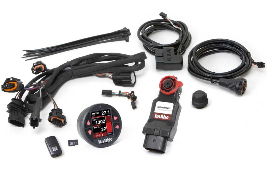
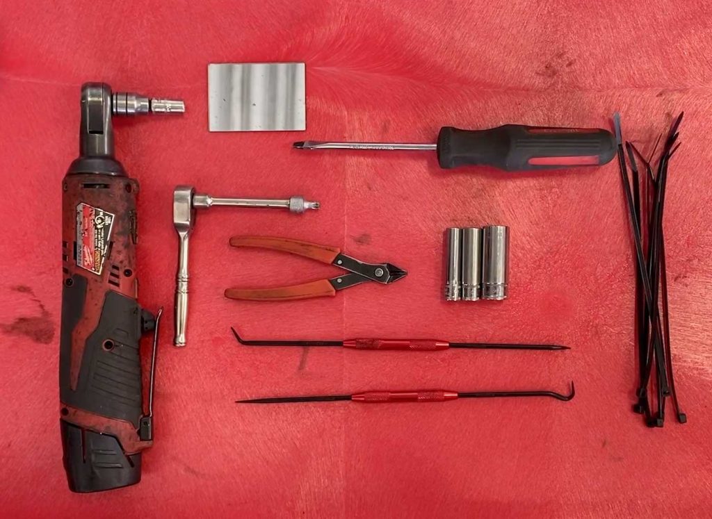
Required Tools
Socket Wrench
Socket Extension
8mm Socket
10mm Socket
14mm Socket
Flathead Screwdriver
Clippers
Assorted Picks
Small Mirror (Optional)
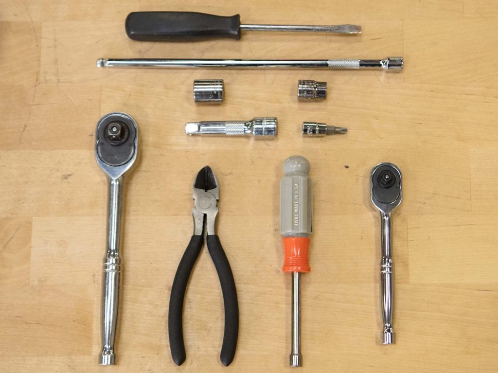
Required Tools
Socket Wrench
Socket Extension
10mm Socket
14mm Socket
T-27 Torx Bit
Flathead Screwdriver
Clippers
7mm Nut Driver
1. Before starting work, familiarize yourself with the installation procedure by reading all of the instructions.
2. The exploded views provide only general guidance. Refer to each step and section diagram in this manual for proper instruction.
3. Throughout this manual, the left side of the vehicle refers to the driver’s side and the right side to the passenger’s side.
4. Disconnect the negative (ground) cable from the battery (or batteries, if there are more than one) before beginning work. The OEM battery clamp can be removed using a 10mm socket or wrench.
5. Route and tie wires and hoses a minimum of 6″ away from exhaust heat, moving parts and sharp edges. Clearance of 8″ or more is recommended where possible.
6. During installation, keep the work area clean. Do not allow anything to be dropped into intake, exhaust, or lubrication system components while performing the installation, as foreign objects will cause immediate engine damage upon start-up.
CAUTION:
Do not use floor jacks to support the vehicle while working under it. Do not raise the vehicle onto concrete blocks, masonry or any other item not intended specifically for this use.
THIS IS A HIGH-PERFORMANCE PRODUCT. USE AT YOUR OWN RISK. Do not use this product until you have carefully read the following agreement.
This sets forth the terms and conditions for the use of this product. The installation of this product indicates that the BUYER has read and understands this agreement and accepts its terms and conditions.
Gale Banks Engineering Inc., and its distributors, employees, and dealers (hereafter “SELLER”) shall in no way be responsible for the product’s proper use and service. The BUYER hereby waives all liability claims.
The BUYER acknowledges that he/ she is not relying on the SELLER’s skill or judgment to select or furnish goods suitable for any particular purpose and that there are no liabilities that extended beyond the description on the face hereof and the BUYER hereby waives all remedies or liabilities, expressed or implied, arising by law or otherwise, (including without any obligations of the SELLER with respect to fitness, merchantability, and consequential damages) whether or not occasioned by the SELLER’s negligence.
The BUYER is responsible for fully understanding the capability and limitations of his/her vehicle according to manufacturer specifications and agrees to hold the SELLER harmless from any damage resulting from the failure to adhere to such specifications.
The SELLER disclaims any warranty and expressly disclaims any liability for personal injury or damages. The BUYER acknowledges and agrees that the disclaimer of any liability for personal injury is a material term for this agreement and the BUYER agrees to indemnify the SELLER and to hold the SELLER harmless from any claim related to the item of the equipment purchased. Under no circumstances will the SELLER be liable for any damages or expenses by reason of the use or sale of any such equipment.
The BUYER is responsible to obey all applicable federal, state, and local laws, statutes, and ordinances when operating his/her vehicle, and the BUYER agrees to hold SELLER harmless from any violation thereof.
The SELLER assumes no liability regarding the improper installation or misapplication of its products. It is the installer’s responsibility to check for proper installation and if in doubt, contact the manufacturer.
The BUYER is solely responsible for all warranty issues from the automotive manufacturer.
Gale Banks Engineering Inc. (hereafter “SELLER”), gives Limited Warranty as to description, quality, merchantability, fitness for any particular purpose, productiveness, or any other matter of SELLER’s product sold herewith. The SELLER shall be in no way responsible for the product’s open use and service and the BUYER hereby waives all rights except those expressly written herein.
This Warranty shall not be extended or varied except by a written instrument signed by SELLER and BUYER. Please see the enclosed warranty information card, or go to www.bankspower.com/warranty, for warranty information regarding your product. All products that are in question of Warranty must be returned shipping prepaid to the SELLER and must be accompanied by a dated proof of purchase receipt. All Warranty claims are subject to approval by Gale Banks Engineering Inc.
Under no circumstance shall the SELLER be liable for any labor charged or travel time incurred in diagnosis for defects, removal, or reinstallation of this product, or any other contingent expense. Under no circumstances will the SELLER be liable for any damage or expenses incurred by reason of the use or sale of any such equipment.
IN THE EVENT THAT THE BUYER DOES NOT AGREE WITH THIS AGREEMENT:
The BUYER may promptly return this product, in a new and unused condition, with a dated proof-of-purchase, to the place of purchase within thirty (30) days from the date of purchase for a full refund, less shipping and/or restocking fee.
The installation of this product indicates that the BUYER has read and understands this agreement and accepts its terms and conditions.
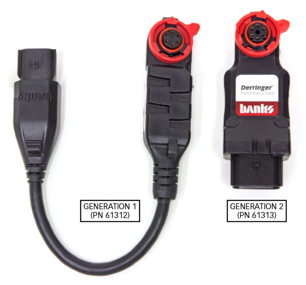
The Derringer is produced in two different form factors.
Generation 1
(PN 61312) is an over-molded design with a pigtail 8-pin connector.
Generation 2
(PN 61313, 66797, 66798, 66799) is housed in a hard plastic case with an integrated 12-pin connector. The function and operation and capability of the GENERATION 1 Derringer and GENERATION 2 Derringer are identical; just the looks and feel of the module have been revised.
NOTE:
The images shown in this manual are for the installation of a GENERATION 1 Derringer. The process for installing the GENERATION 2 is identical.
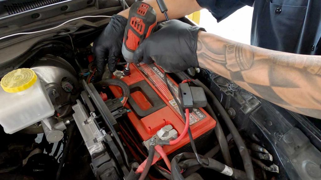
1. Before beginning, disconnect the negative terminal of the battery.
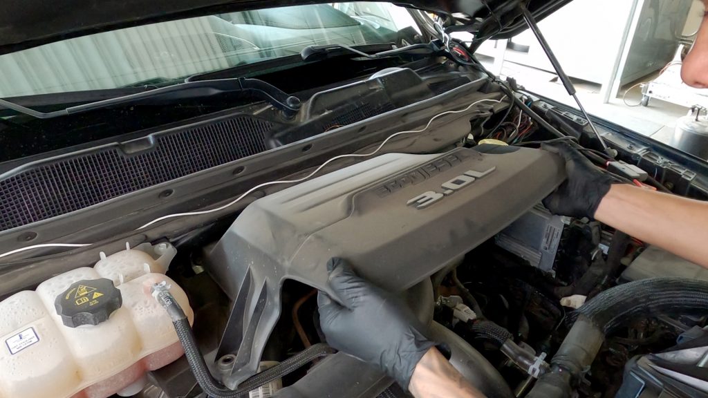
2. Once the battery is disconnected, remove the engine cover.
2014-2018 Ram 1500 – First remove the oil cap. Then, lift up at the front to release the rubber socket mounts and pull forward to release from the rear mounts. Reinstall the oil filler cap.
For 2020+ vehicles remove the two 10mm bolts holding the cover on.
NOTE: If installing in a 2014-2018 Jeep Grand Cherokee, skip steps 3 & 4 and proceed to step 5.
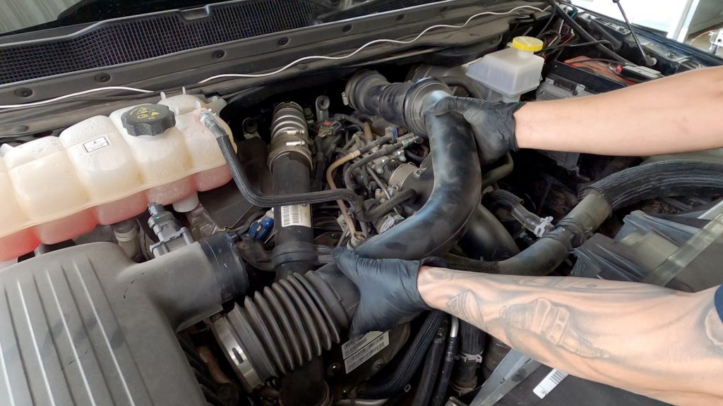
3. Remove the intake hose.
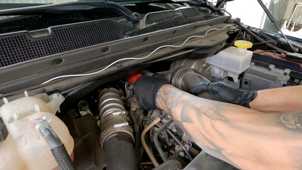
4. There are four mounting locations and one sensor to disconnect.
Using the 8mm socket, loosen the hose clamp on one end of the intake.
There is a clamp that’s partially covered by the lip of the firewall.
Remove the third bolt attached to the bracket.
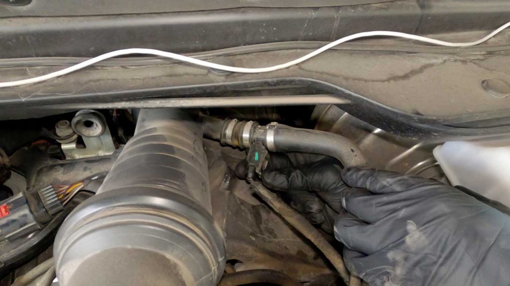
5. Disconnect the closed crankcase heater ventilation connector.
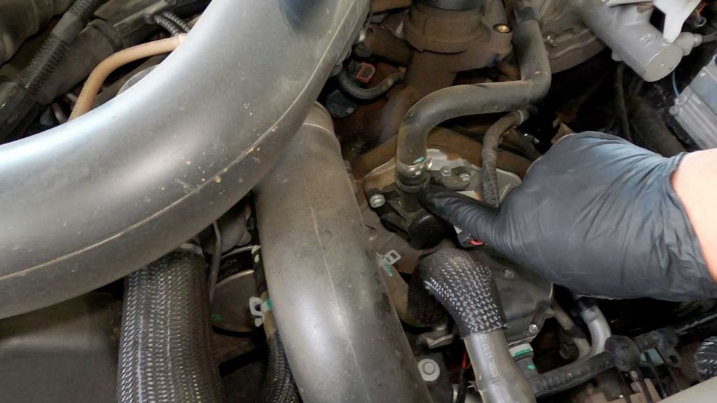
6. Squeeze the clamp at the base of the crankcase breather hose to disconnect it.
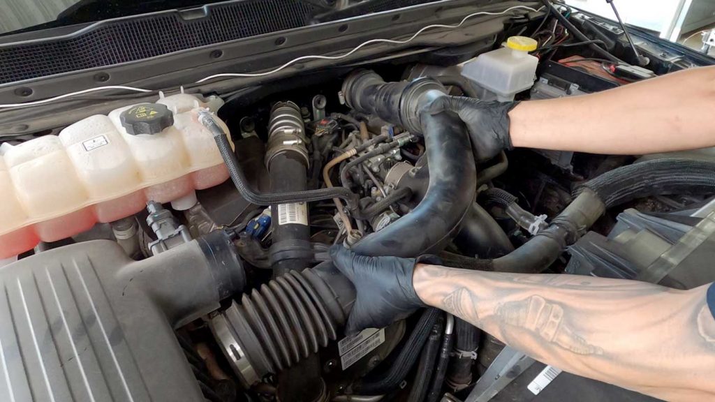
7. Pull the intake up and out, but do not fully remove.
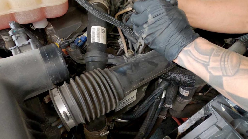
8. There’s a small harness clip attached to the intake, remove the clip to disconnect the harness.
Now you can fully remove the intake hose.
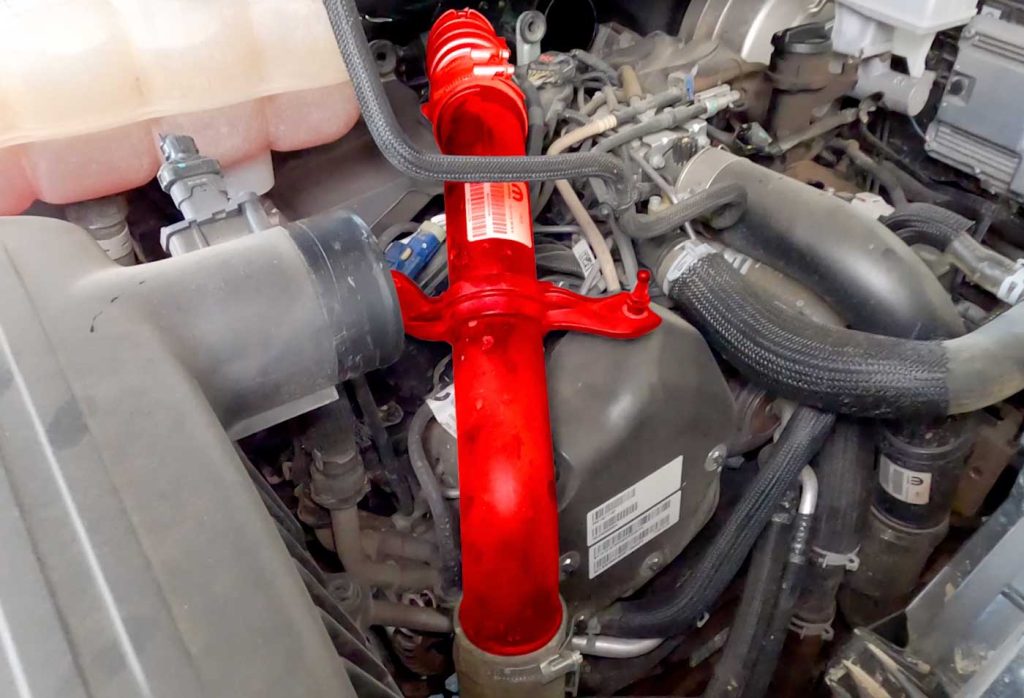
9. Remove the charge air cooler hose from the turbocharger.
Using a 14mm socket, remove the bolt retaining the duct to the engine.
Loosen the hose clamp at the bottom of the duct using an 8mm socket.
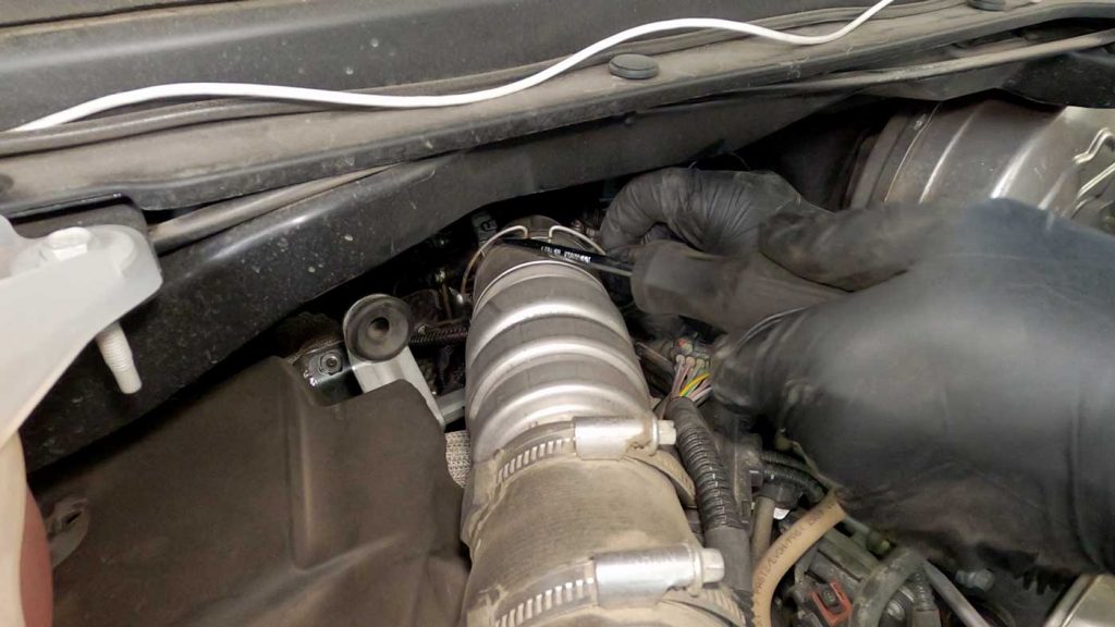
9A. Using a flathead screwdriver or pick, pry the metal retaining clip up until it clicks out.
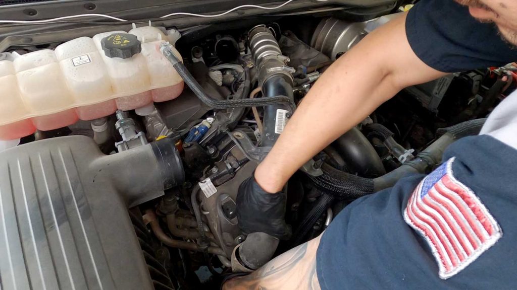
10. Gently slide the duct off the elbow and remove the duct.
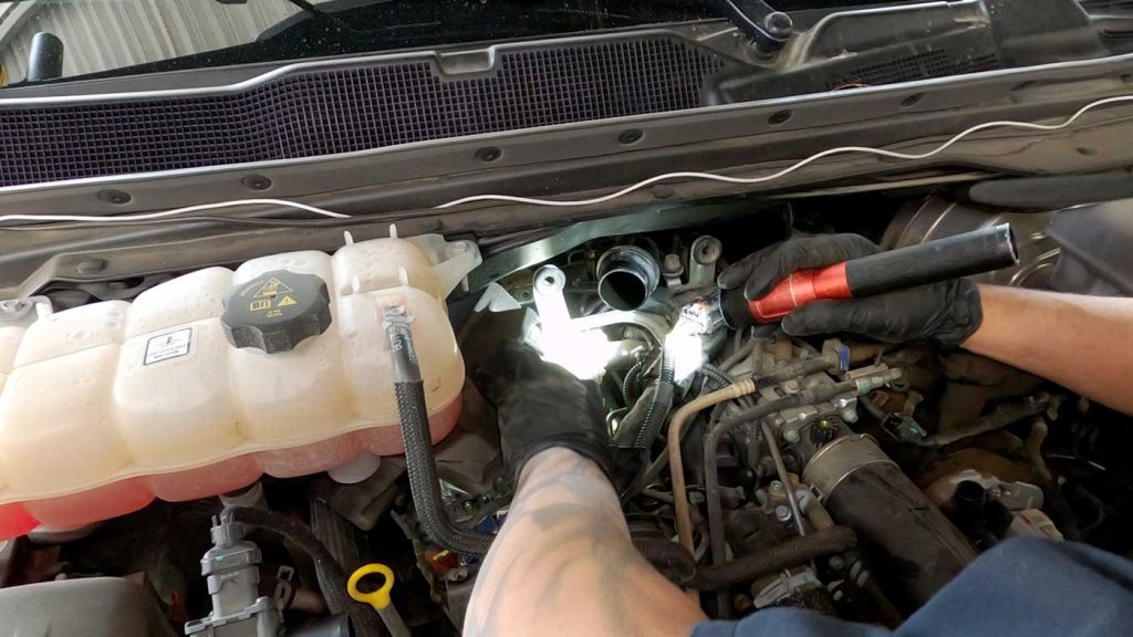
11. Move the sound deadening foam out of the way so you have visual access to the FRP (fuel rail pressure) sensor.
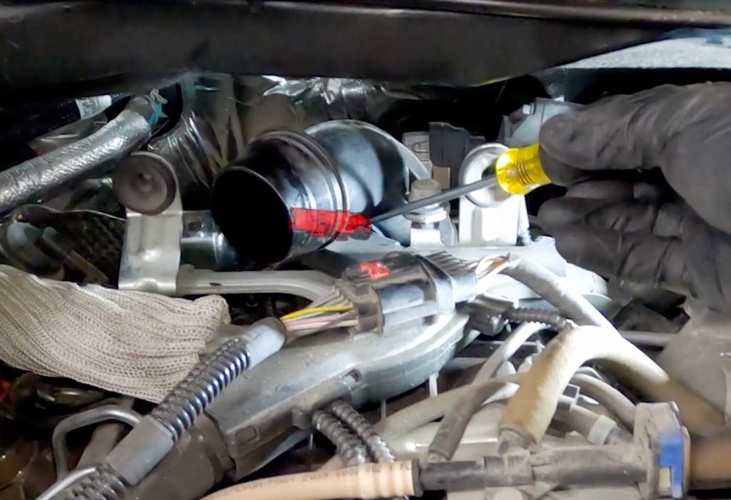
12. It’s time to remove the MAP sensor.
Clocking the sensor can determine how difficult the remaining steps will be.
From 9 to 3 o’clock – you should be able to easily unlock and disconnect the sensor.
Locked at 6 o’clock – this will be the most difficult orientation.
Once you’ve made the orientation of the sensor, disconnect the MAP sensor.
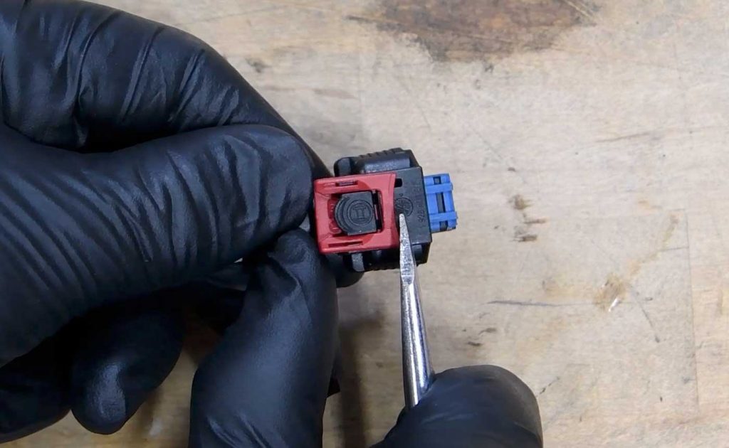
13. Using a flathead screwdriver, you can see the locking tab on the MAP sensor through the bracket.
Unlock the tab and squeeze the sensor to disconnect and then store it for future use.
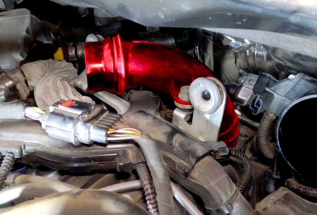
14. Remove the turbo outlet elbow coming off the turbocharger.
Using the T-30 Torx, access the two bolts on the bottom of the flange of the elbow.
Remove the two bolts and wiggle the elbow to remove it.
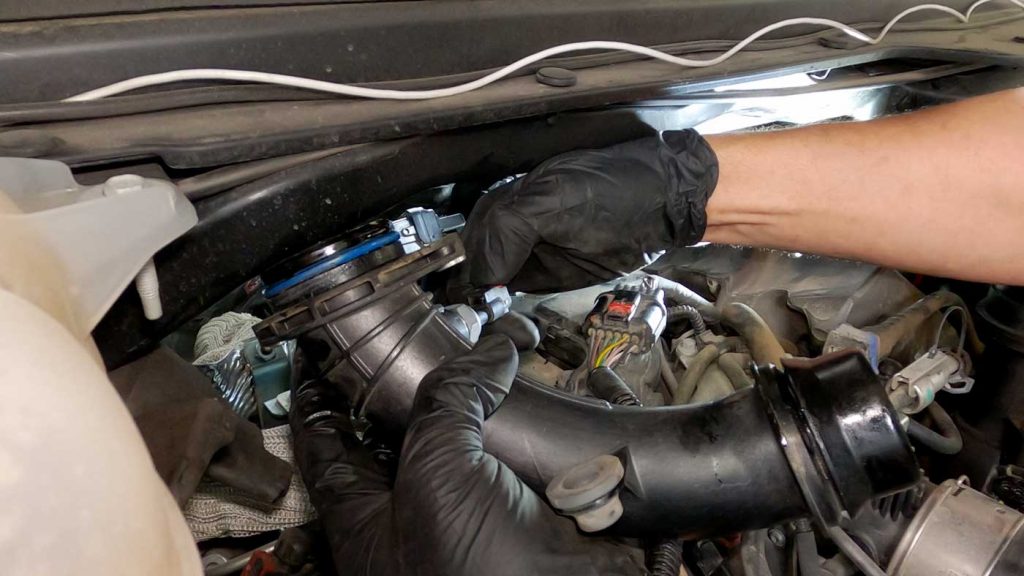
15. Disconnect the air temperature sensor on the backside of the elbow by sliding the red locking mechanism back and depressing the tab and pulling the connection apart.
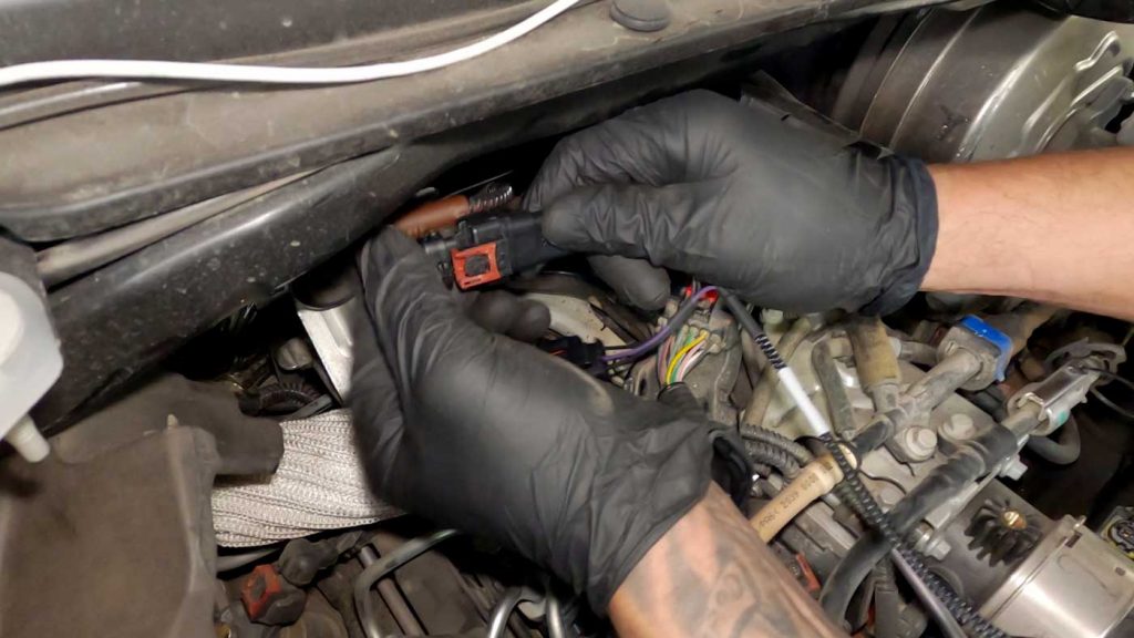
16. Now it’s time to disconnect the fuel rail pressure sensor.
Verify the orientation of the sensor.
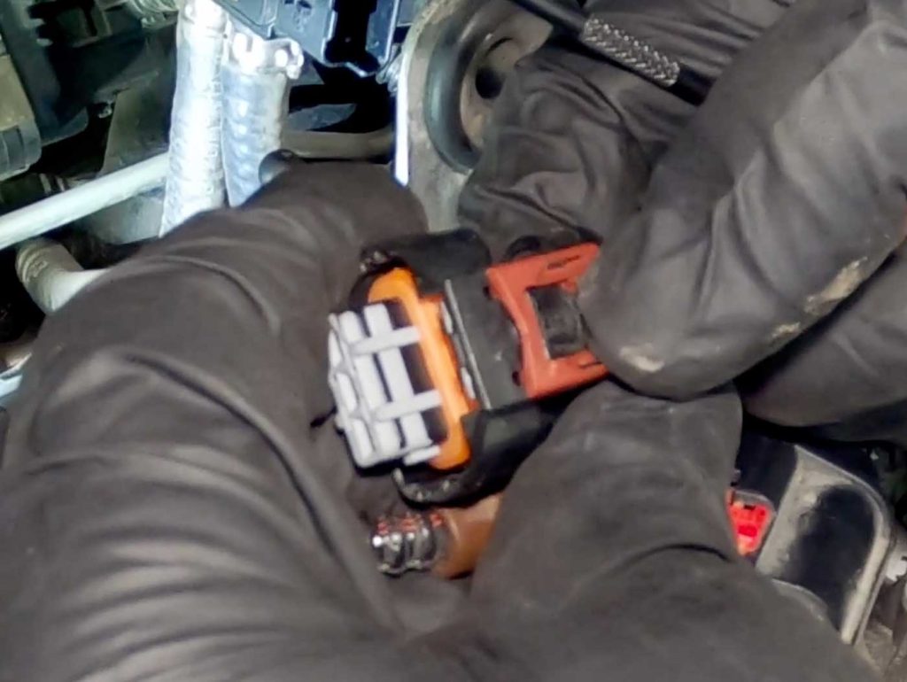
17. As shown in the video above, the locking mechanism is hidden on the underside of the sensor.
You’ll need to slide the locking mechanism back. Then squeeze the tab to release.
We used a small mirror to help us guide our tools.
Once you hear and feel the click of the locking mechanism, you can squeeze the tab and pull the sensor off its housing.
Use a small flathead screwdriver to keep pressure on the sensor as you disconnect it.
18. Set aside the disconnected sensor, as you will be plugging it into the Derringer.
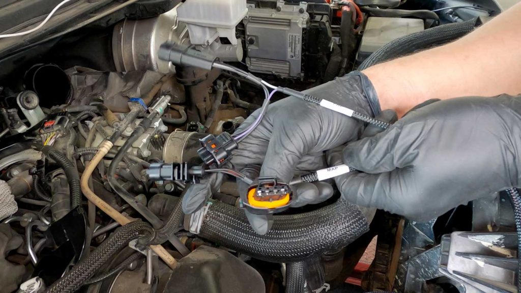
1. Begin installing the Derringer by first connecting the wiring harness.
2. The wire harness extension is marked FRP and MAP.
The FRP is a three-pin connector.
While the MAP is a four-pin connector.
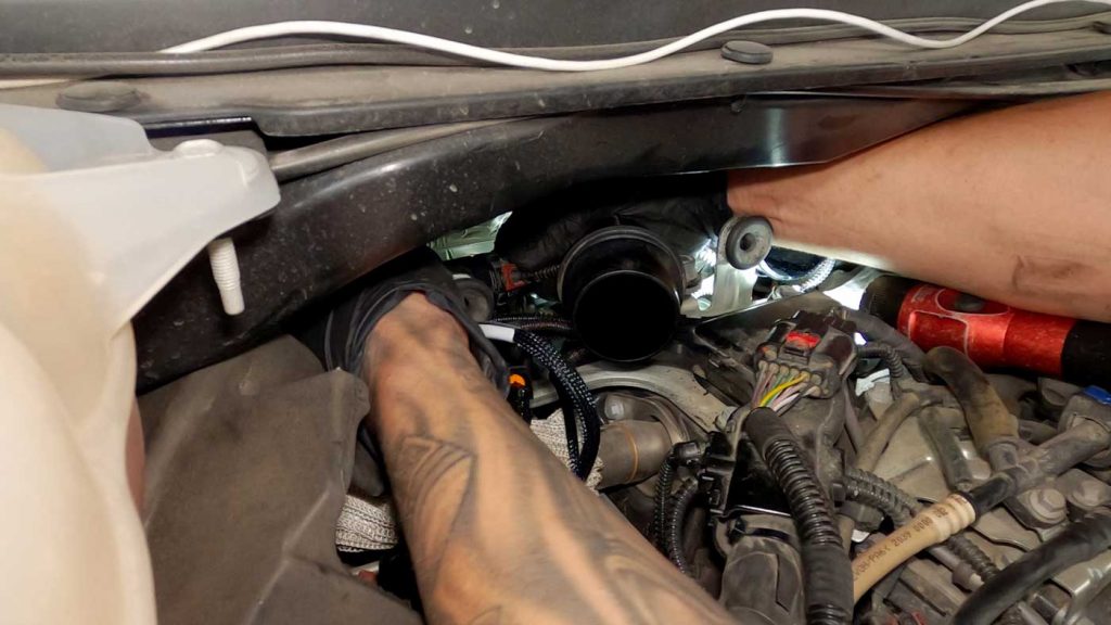
3. Connect the Banks FRP extension to the factory FRP sensor.
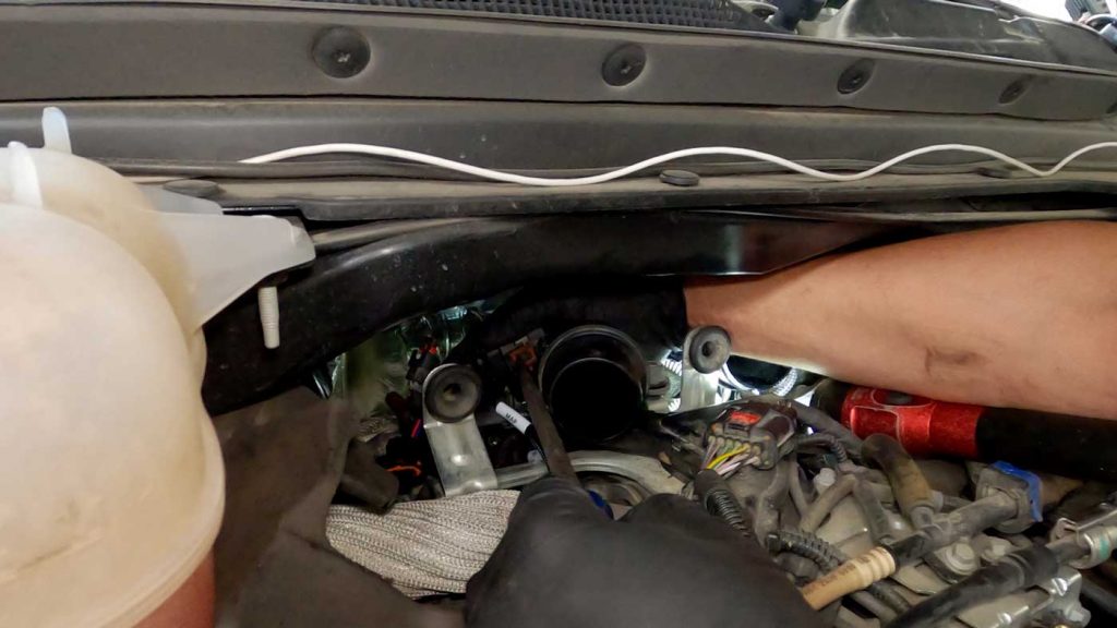
4. Install the FRP extension connector into the back of the fuel rail and push until you hear a click.
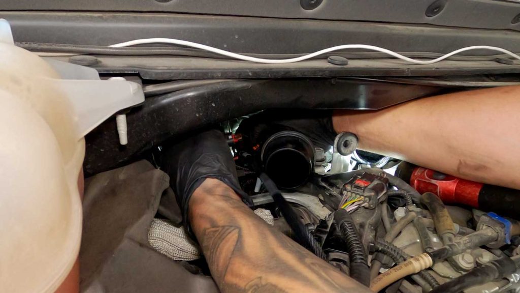
5. Reinstall the turbo outlet elbow back on top of the turbocharger.
6. Place the two bolts back into their position and tighten slightly to help hold the elbow in place.
7. Use the T-30 Torx to fasten the bolts back into position.
8. Reconnect the air temp sensor on the backside of the elbow.
9. Reconnect the MAP sensor.
Clip the Banks harness extension into the factory MAP sensor.
Use the flathead screwdriver to help push the locking mechanism back into the locked position.
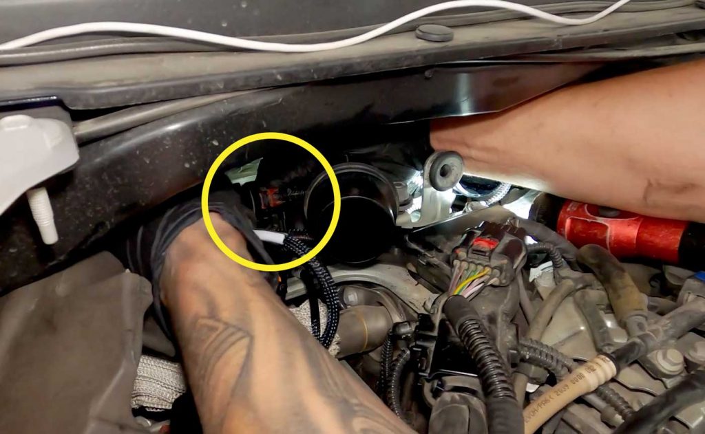
10. Connect the Banks harness extension into the main wiring harness.
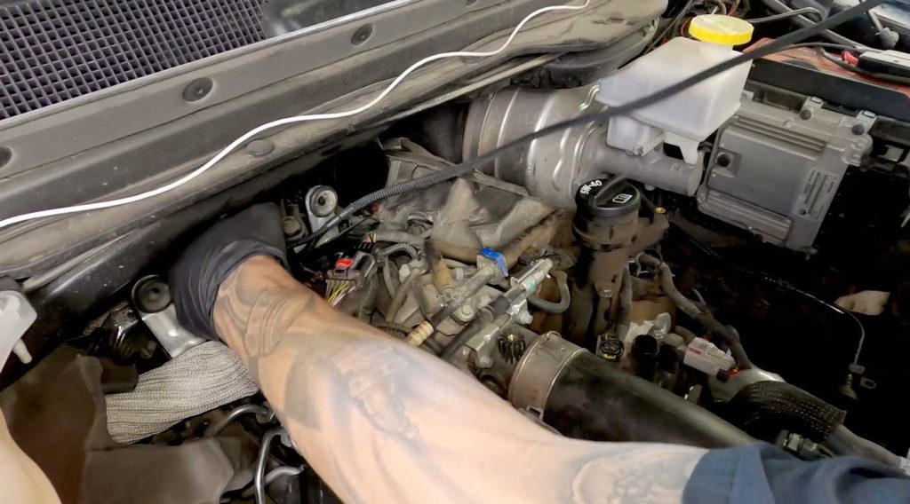
11. Lay the Banks harness extension out in your desired route.
Be sure to avoid areas of extreme temps and moving/rotating parts.
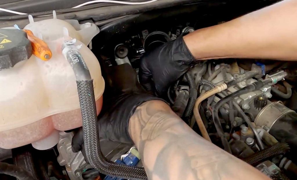
12. Move back or reinstall the sound deadening foam.
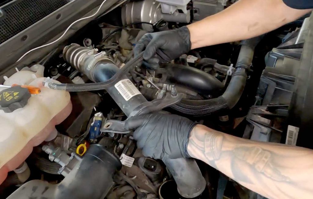
13. Reinstall the charge air cooler hose.
Slide the upper end back over the turbo outlet elbow until you hear the click of the retaining clip going back into position.
Then slide the bottom of the hose back into the tube and tighten down the hose clamp with an 8mm socket.
Reinstall the bolt for the mid-point bracket using a 14mm socket.
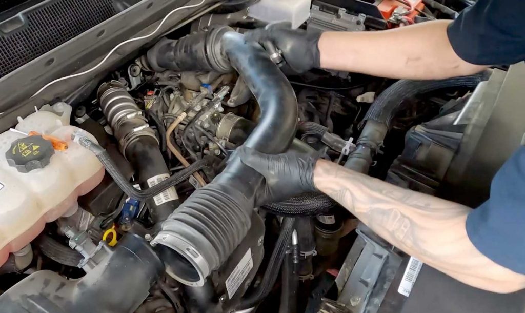
14. Reinstall the intake hose.
Slide the rubber boots back onto their respective ends of the system.
Push the center mount down until you feel it pop into position.
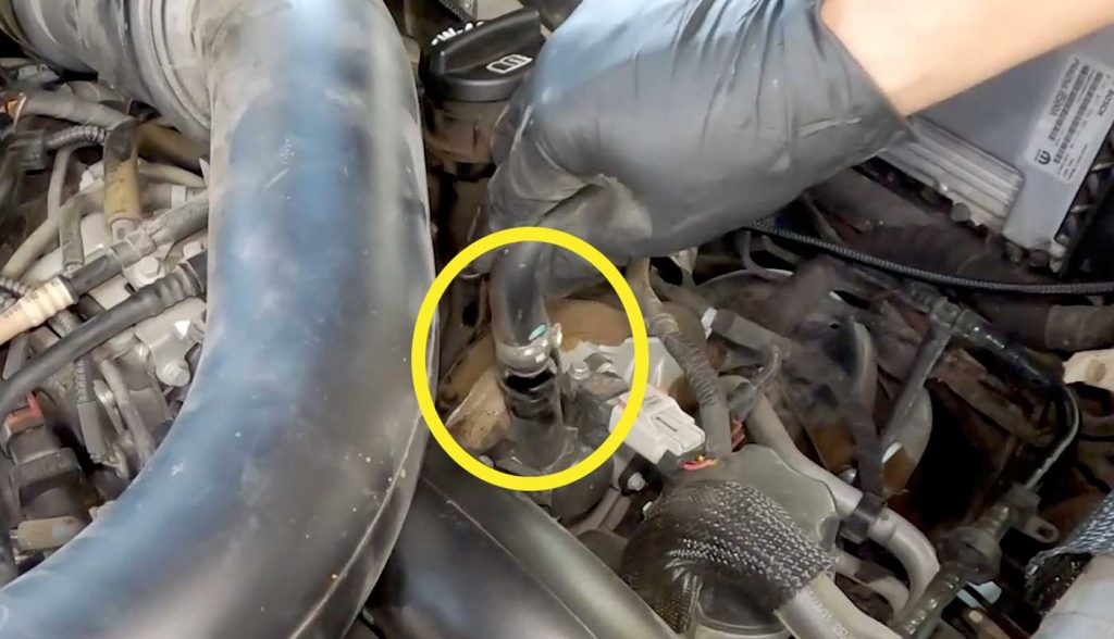
15. Reinstall the crankcase breather hose by pushing it firmly onto the duct.
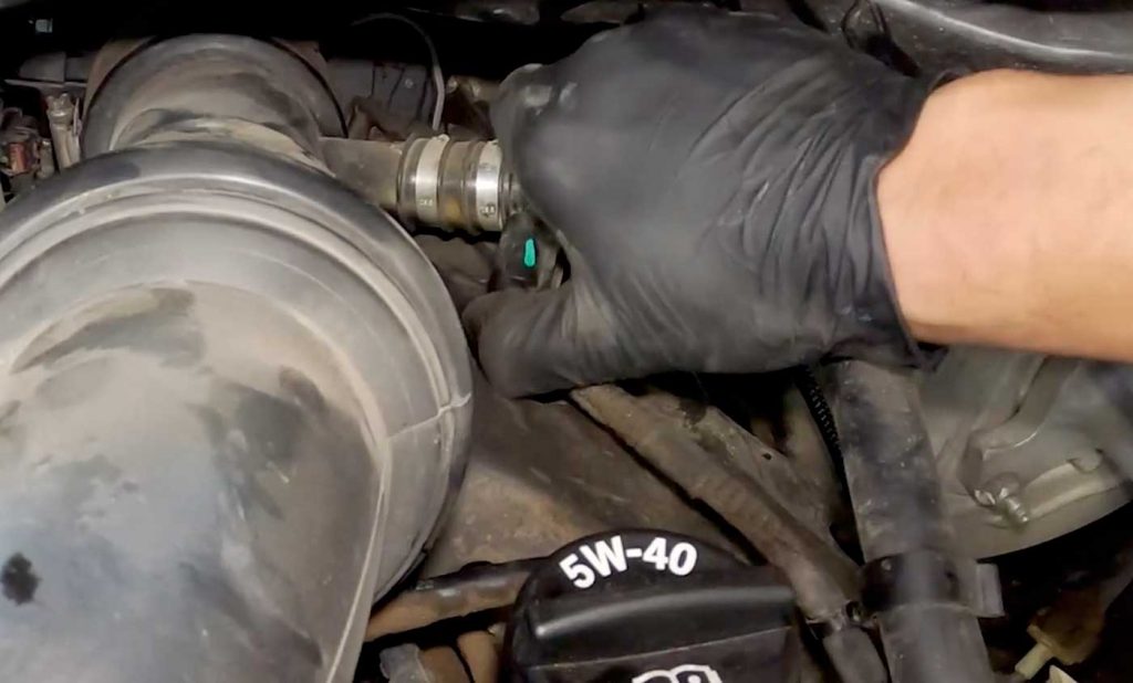
16. Reconnect the closed crankcase heater ventilation connector.
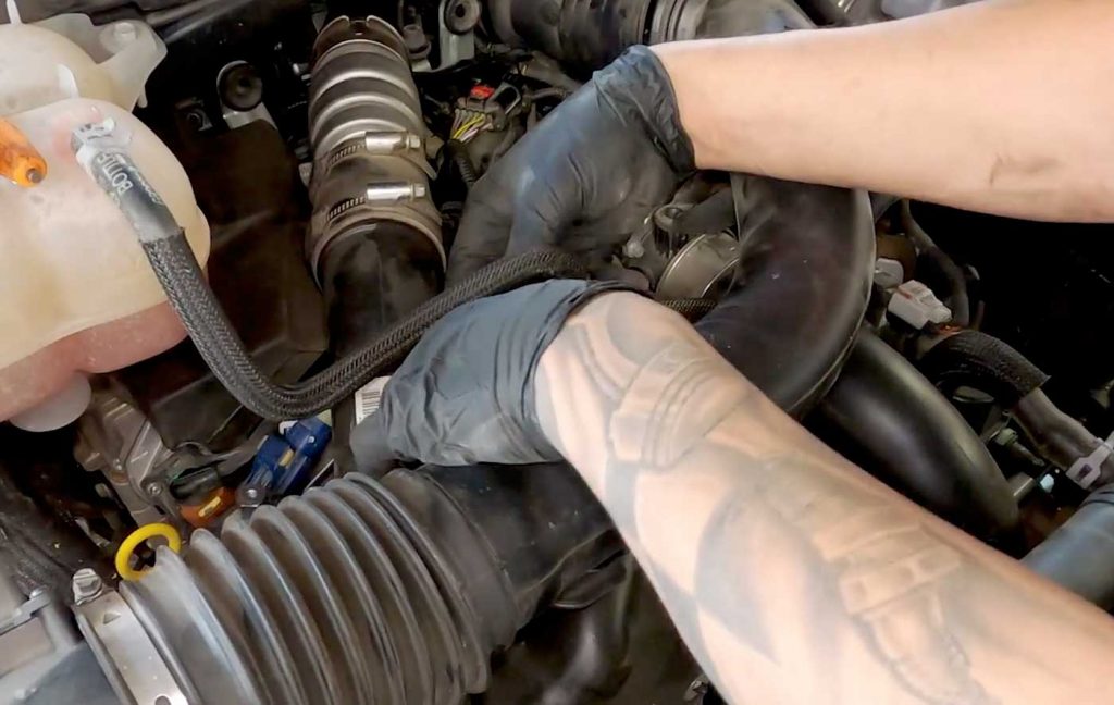
17. Reattach the wire harness to the intake hose.
18. Ensure that the intake hose is properly over the ducts and use your 8mm socket to fasten them.
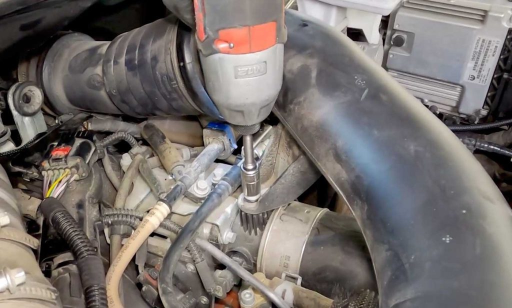
19. Install the 10mm bolt at the center bracket of the intake hose.
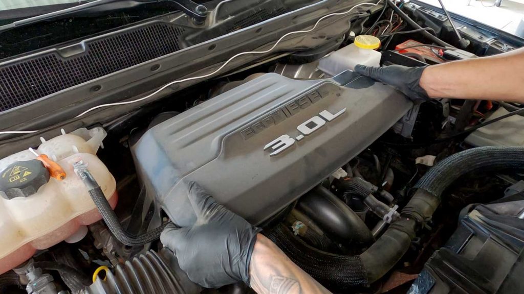
20. Reinstall the engine cover.
Secure it by reinstalling the two 10mm bolts.
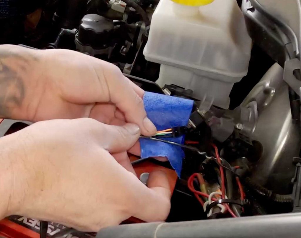
1. Use a coat hanger and low adhesive tape to tape the iDash cable to the hanger to fish them through the firewall.
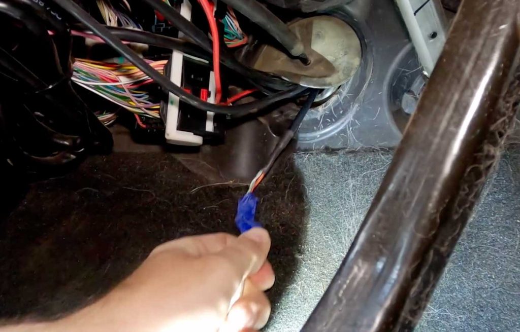
2. Pull the fish through the hole and pull in as much as the iDash cable as possible. Remove the tape and set it aside.
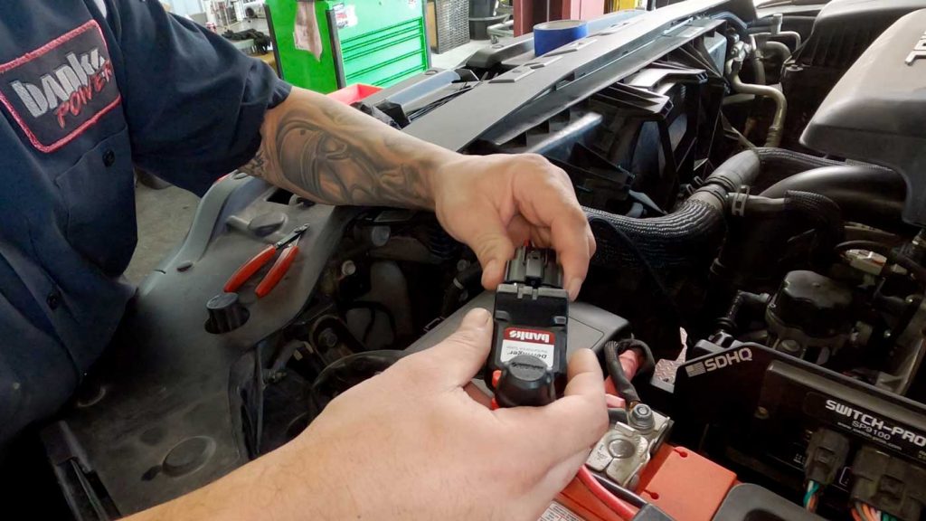
3. Take the Banks Derringer cable harness and plug it into the bottom of the Derringer.
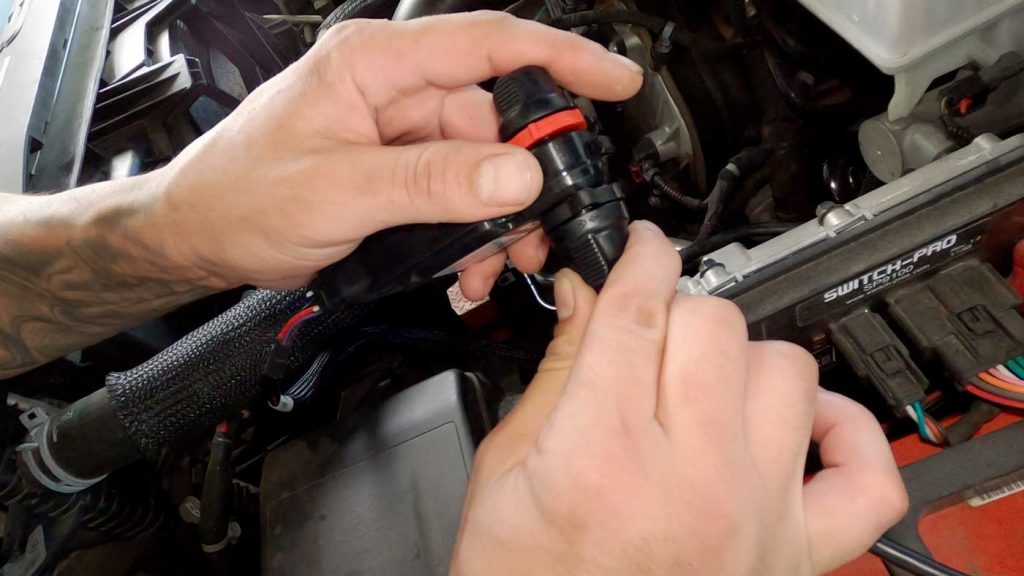
4A. Connect the iDash cable to the Derringer by lining up the keying features.
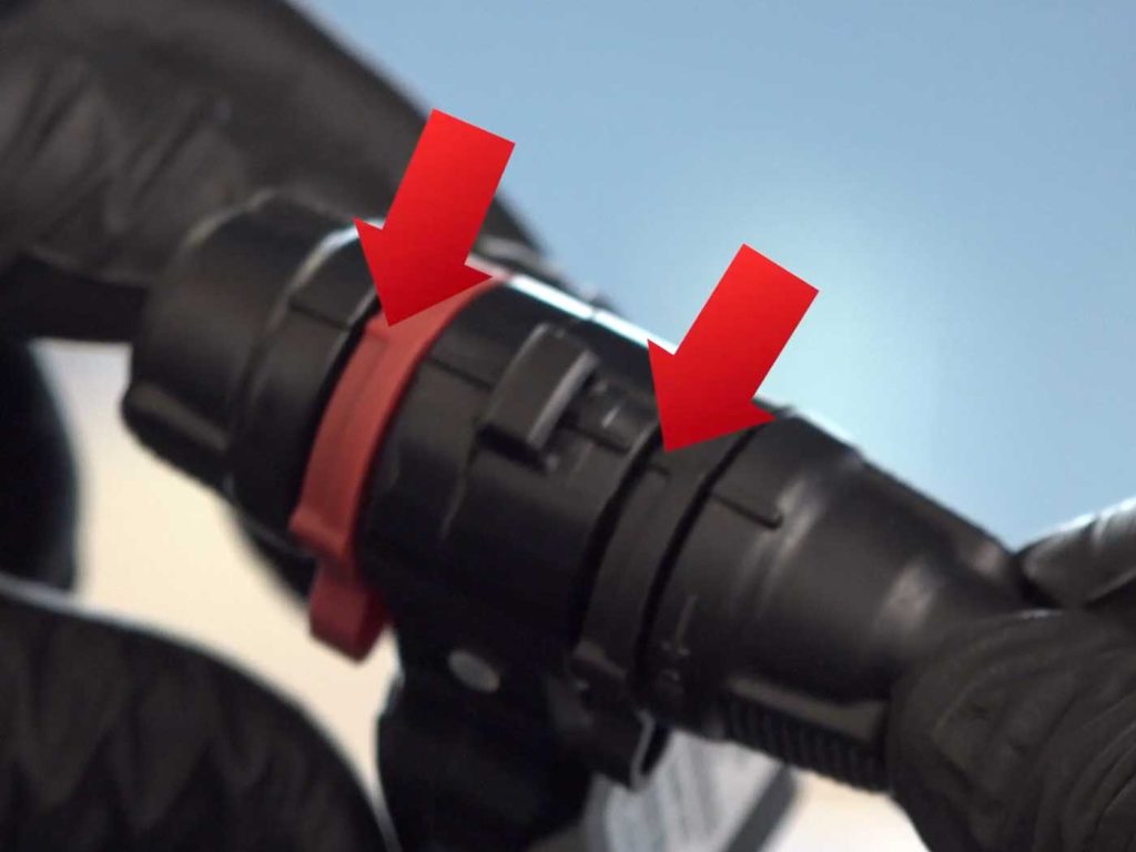
4B. Lock it into place by twisting the outer ring to line up the indicators.
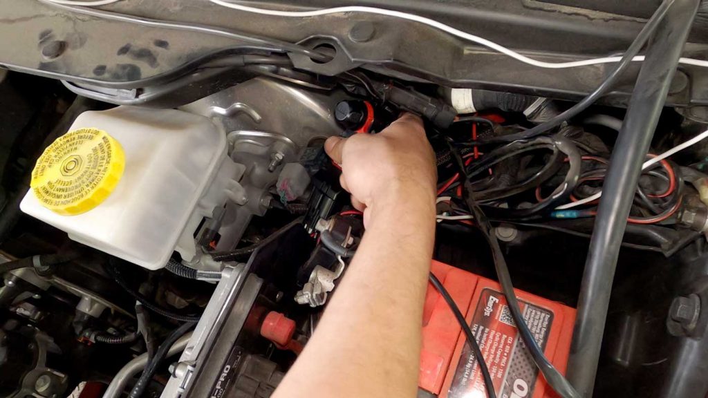
5. Choose the desired location for your Derringer module.
Using the supplied zip ties, secure the Derringer.
6. Go back through the harness routing and make sure that it is clear of any moving parts or areas of extreme temperatures.
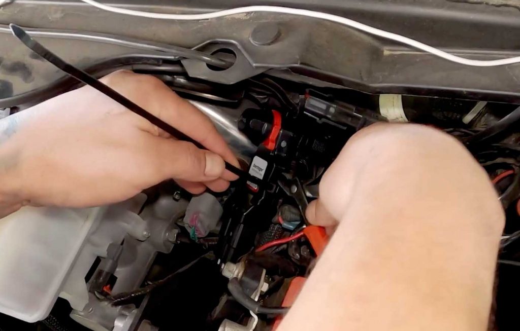
7. Secure the routing using the supplied zip ties.
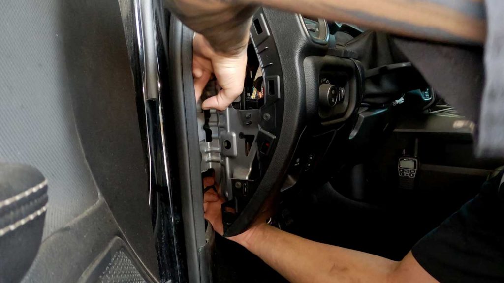
8. In the cabin of the truck, connect the iDash.
Remove the side panel of the dashboard.
Fish the iDash, Derringer, and OBD cables through the side of the dashboard.
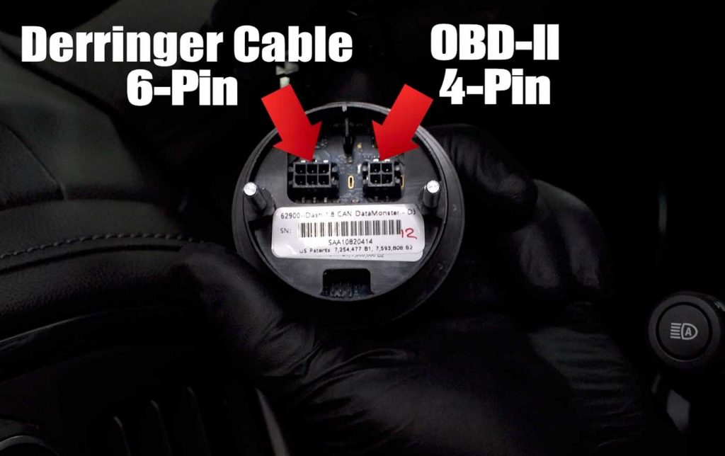
9. Connect the Derringer to the iDash.
If you already have the iDash installed, remove it from the mount in order to access the connectors.
There are two connections on the back of the iDash.
The Derringer cable plugs into the 6-pin slot, and the OBD-II plugs into the 4-pin slot.
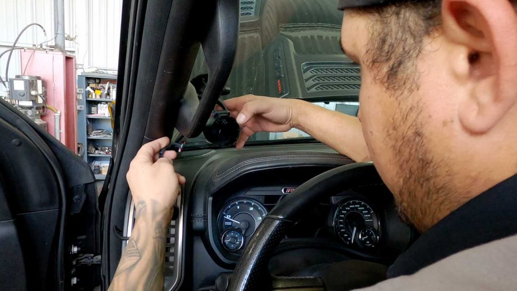
10. Tuck away the cables and mount the iDash.
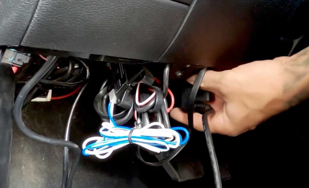
11. Connect the OBD cable to the OBD-II port.
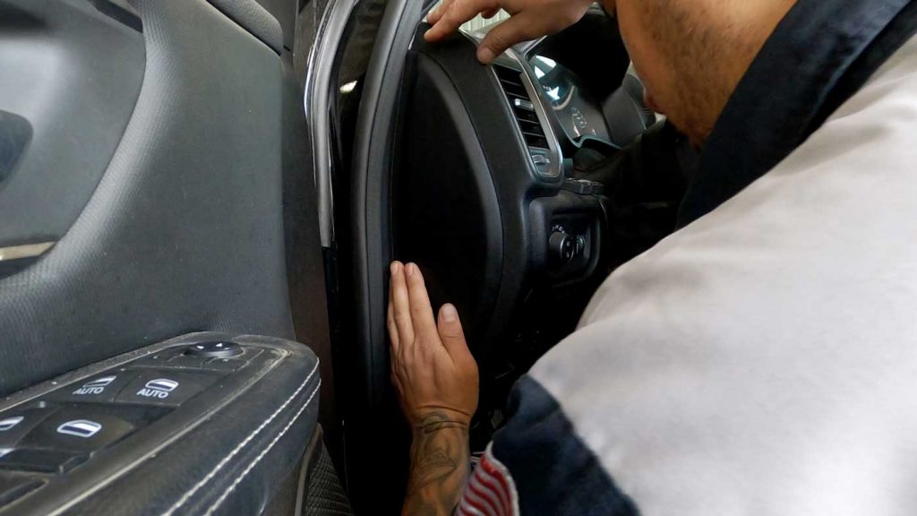
12. Put the side panel back on the dashboard.
Secure the cables to ensure they do not catch your feet while driving.
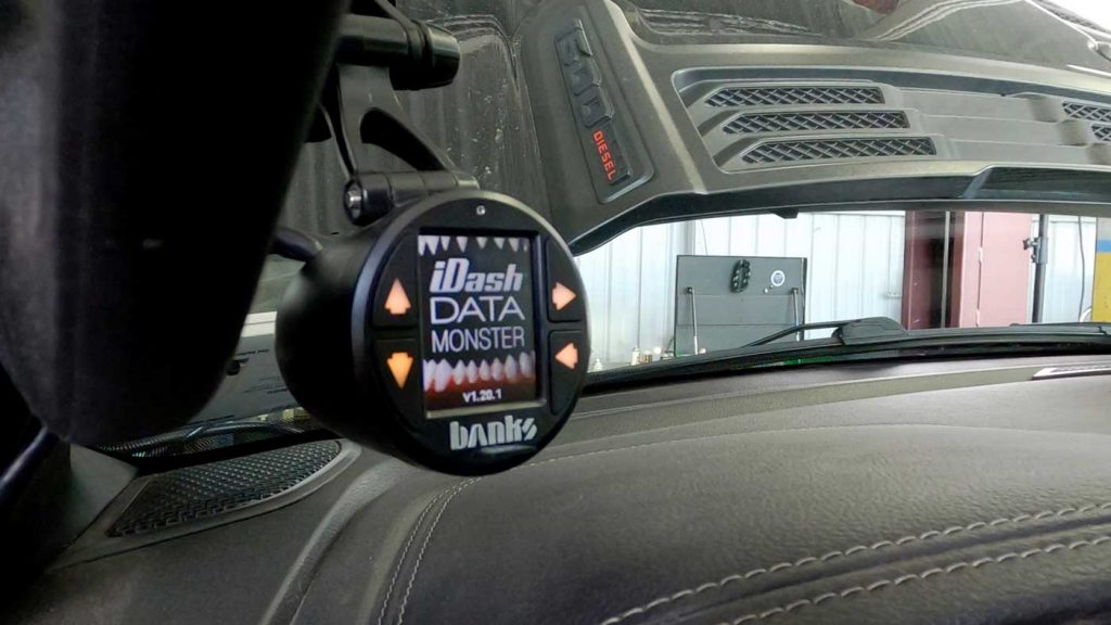
13. Reconnect the battery and power up the truck to confirm that the Derringer is connected and working properly.
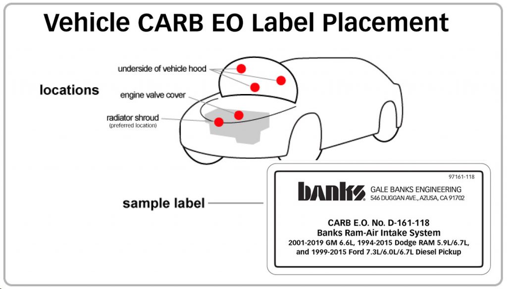
CARB EO Label
Please use the following CARB-approved emissions label and EO label location guidelines. We generally use the radiator shroud location.
Congratulations!
You have now installed the Derringer Tuner!