


Proven Diesel Power
Test and install of Banks PowerPack for Dodge/Cummins 12-valve turbo-diesel trucks
We’ve all run across performance products that are claimed to make tremendous power gains—sometimes too tremendous to believe. However, you can believe what you hear in the case of the diesel PowerPack kits from Gale Banks Engineering, specifically the kits for the Dodge Cummins turbodiesel engines. A true 114 percent increase in horsepower and 81 percent more torque are possible with simple-to-install bolt-on parts.
We couldn’t resist the prospect of waking the sleeping giant under the hood of a 1997 Dodge turbodiesel, so we followed the installation of a complete PowerPack system at Gale Banks Engineering. At the end, we did a dyno-test thrash to see if we could duplicate the numbers.
As it turns out, the PowerPack system didn’t just wake the sleeping giant, it made him downright mad. We suspected the Cummins turbodiesel engine was a good candidate to make serious horsepower (a version of the engine found in Dodge trucks is used to propel some 18-wheelers), and even though our test truck didn’t exactly duplicate the Banks claims for reasons we’ll explain later in this article, the power a few basic bolt-on parts yielded is impressive. Beyond the power gains, the quality and fit of the components are among the best we’ve seen, and the detailed instructions were written with the do-it-yourselfer in mind. Find out what it takes to install a Banks PowerPack kit in the photos and captions (above), and then check out the acceleration and dyno-test results.
The truck we used for this article is a 1997 3/4-ton Club Cab 4×4 with an automatic and 17,584 miles on the clock at the time of the modifications. It was chassis dyno-tested at Banks’ facility before and after the installation, and we performed 0-60 acceleration tests and 40-60 passing acceleration tests with the truck both unloaded and pulling a 7,248-pound trailer. Mileage was also scrutinized before and after to see what the gains or losses would be.
Dyno Test Results – 1997 Ram2500 Cummins
| RPM | Stock HP | Banks HP | Stock Torque | Banks Torque |
|---|---|---|---|---|
|
1,400
|
111
|
166
|
417 lbs./ft.
|
623 lbs./ft.
|
|
1,500
|
122
|
183
|
427 lbs./ft.
|
641 lbs./ft.
|
|
1,600
|
128
|
200
|
422 lbs./ft.
|
655 lbs./ft.
|
|
1,700
|
134
|
213
|
414 lbs./ft.
|
657 lbs./ft.
|
|
1,800
|
140
|
225
|
409 lbs./ft.
|
656 lbs./ft.
|
|
1,900
|
147
|
239
|
406 lbs./ft.
|
661 lbs./ft.
|
|
2,000
|
153
|
248
|
403 lbs./ft.
|
651 lbs./ft.
|
|
2,100
|
155
|
249
|
389 lbs./ft.
|
623 lbs./ft.
|
|
2,200
|
163
|
251
|
389 lbs./ft.
|
598 lbs./ft.
|
|
2,300
|
174
|
251
|
397 lbs./ft.
|
572 lbs./ft.
|
|
2,400
|
177
|
251
|
388 lbs./ft.
|
548 lbs./ft.
|
|
2,500
|
178
|
243
|
374 lbs./ft.
|
510 lbs./ft.
|
The results were impressive. Although our findings (251 hp at 2,200 rpm and 661 lb-ft of torque at 1,900 rpm) were somewhat less than what Banks has found on other trucks it has tested (264 hp at 2,600 rpm and 697 lb-ft of torque at 1,900), we were astonished with how big a difference the PowerPack makes. Gale Banks pointed out that the discrepancy between the power numbers is because the truck we chose for testing is a California model equipped with an EGR valve. When you consider our numbers, remember that we’re talking rear-wheel horsepower, which takes into account the power losses in the rest of the drivetrain, and the findings still show significant power gains.
Another surprise was the change in mileage. Typically a major performance modification will hurt gas mileage, but that was not the case with the PowerPack. With the truck both unloaded and loaded, it increased almost 2 mpg. And as though all this other stuff weren’t enough, the PowerPack knocked between 2 and 5 seconds off every acceleration test. The one factor that wasn’t reflected in the testing was the drastic driveability changes. Before the mods, the owner noted that it took time for the turbo to spool up and that passing, especially when loaded, had to be planned far in advance. Now, the owner happily reports that with plenty of power on demand, the big diesel feels much closer to a gas engine, and it can pull up grades better than it ever could before.
| Stock | with Banks HP | |
|---|---|---|
|
0-60 – unloaded
|
16.4
|
14.1
|
|
0-60 – loaded
|
26.2
|
22.8
|
|
40-60 – unloaded
|
17.4
|
15.6
|
|
40-60 – loaded
|
29.08
|
23.9
|
|
MPG – unloaded
|
17.4
|
19.2
|
|
MPG – loaded
|
15.8
|
17.8
|
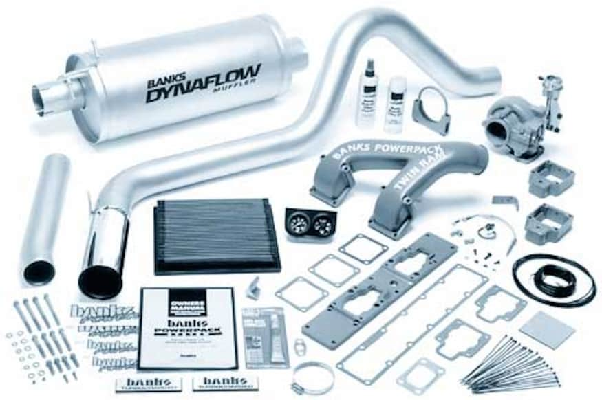
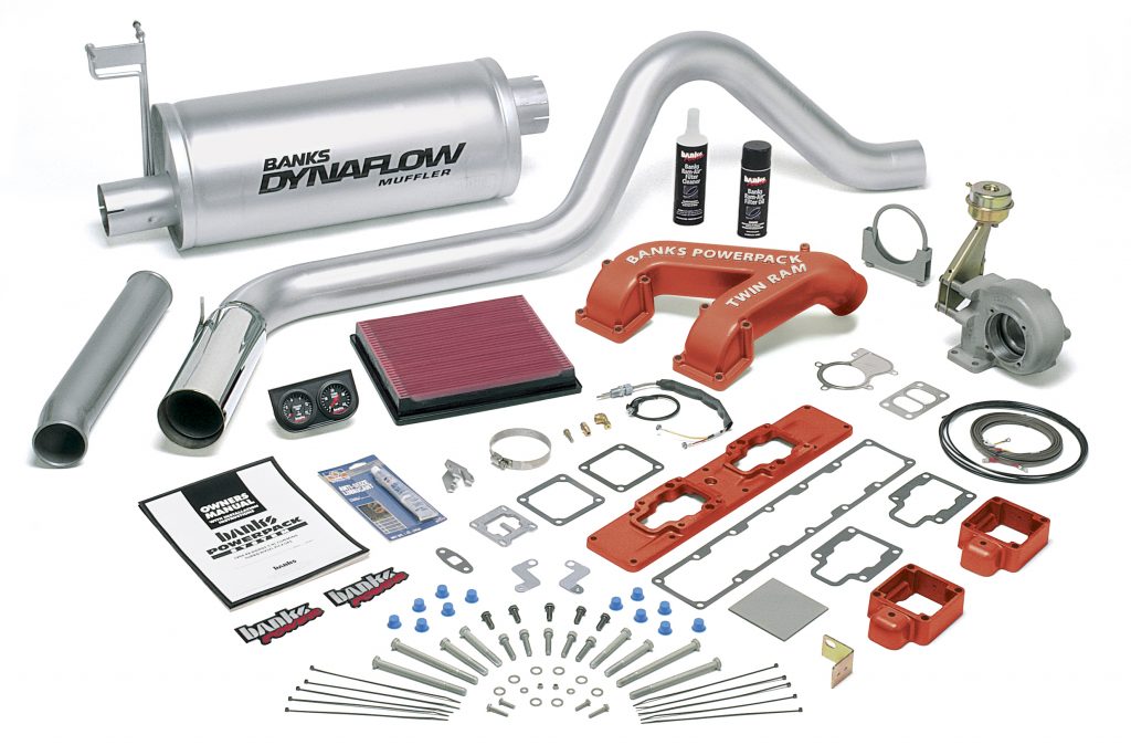
The Banks PowerPack system consists of an air filter, an intake manifold, a revised turbo housing, an exhaust system, a fuel-calibration plate, and gauges–not a lot of parts when you consider the gains. There’s no magic to the parts; they’re simply engineered to work well together as a system. Plus, thanks to the detailed instructions (which include plenty of diagrams), a shadetree mechanic with an average-sized toolbox can install the system over a weekend.
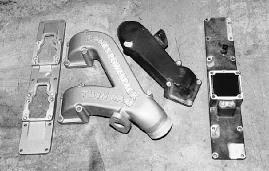
One of the key components to the PowerPack system is the Twin Ram intake manifold. Instead of a single inlet to feed all the cylinders, the Twin Ram splits the intake, providing better air and boost distribution to the engine. After looking at the original intake, it’s hard to see why the engineers didn’t do it this way from the factory.
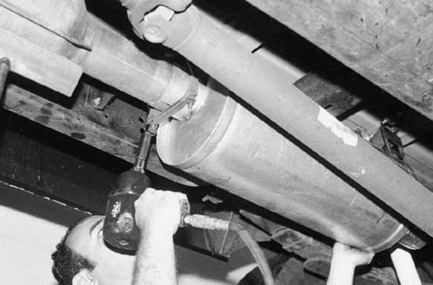
The first step of the installation involves removing the original muffler and tailpipe assembly. Although the tailpipe appears large (about 3 1/2 inches) at the end, it necks down over the rearend and is a restriction. The Banks tailpipe is 3 1/2 inches throughout. The stock system is clamped together, but it’s necessary to heat the slip joints to ease removal without damaging the rest of the system. The factory clamps and hangers are reused with the new muffler assembly, and no cutting or welding is required. The catalytic converter has a tab that indexes a notch on the muffler, taking the guesswork out of proper positioning.
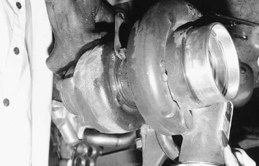
Disconnect the intake and exhaust plumbing from the turbo housing, then carefully loosen the mounting bolts and remove the turbo from the exhaust manifold. Place the turbo assembly in a vise. It’s necessary to separate the exhaust portion of the assembly, so scribe a mark between the two pieces to ensure the new Banks piece can be positioned the same way on the turbo. Unbolt the wastegate assembly per the instructions, loosen the bolts connecting the two pieces, and carefully separate them. It may be necessary to lightly tap the connection to persuade the parts to separate, and be sure to remove any residual rust before installing the new turbine housing.
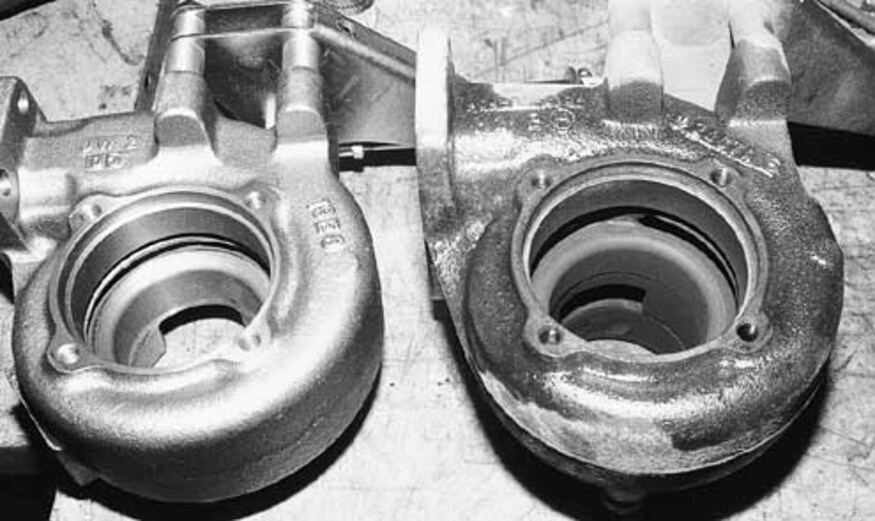
There is not much visible difference between the Banks Quick Turbo housing (left) and the original. However, the revised one allows the turbo to spool up quicker, providing more power at a lower rpm. Transfer the appropriate parts from the original to the new housing, and note how the original was positioned so that you know how to install the new housing.
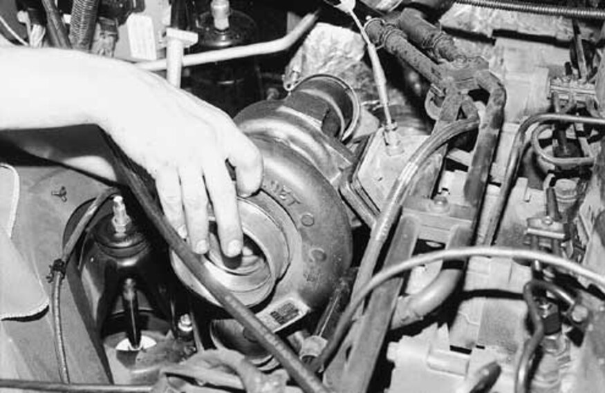
Before reinstalling the turbo housing, drill and tap a hole in the rear outlet of the exhaust manifold. Stuff a rag in the exhaust port before drilling to catch the metal particles, and thoroughly clean the port with a vacuum to ensure these particles don’t damage the rest of the system. This hole will be the location for the pyrometer sending unit, which is included with the PowerPack kit.
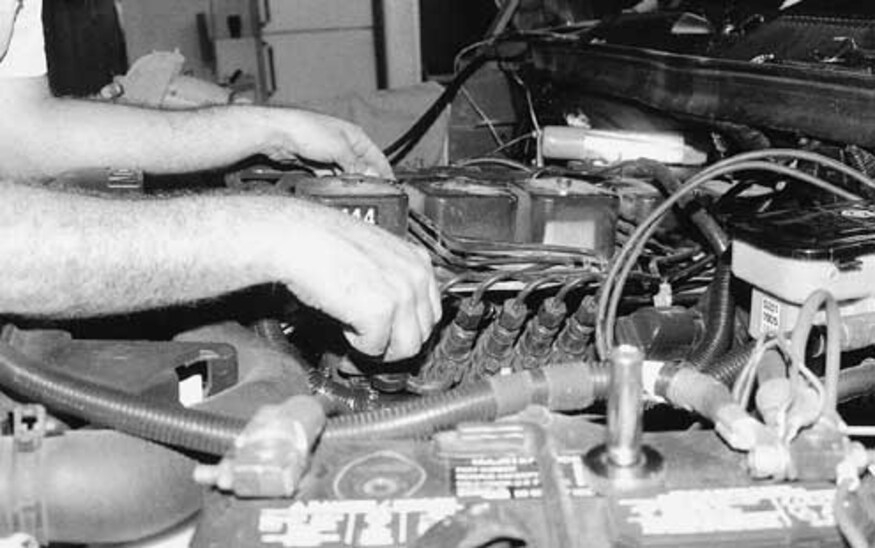
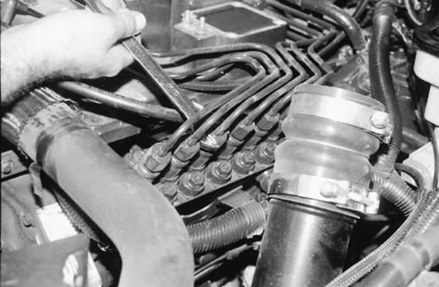
Remove the intake-manifold cover and the inlet port (or upper intake). Start loosening the fuel lines that run from the injector pump to the injectors on the other side of the engine with a line wrench if one is available. Use caution when lifting away these steel lines, and do not attempt to bend them–they’re easy to damage and expensive to replace. The fuel lines can be removed as an assembly. Use the plastic caps supplied with the kit to cover the outlets on the injector pump. Any debris that enters the fuel system can have disastrous effects on the engine.
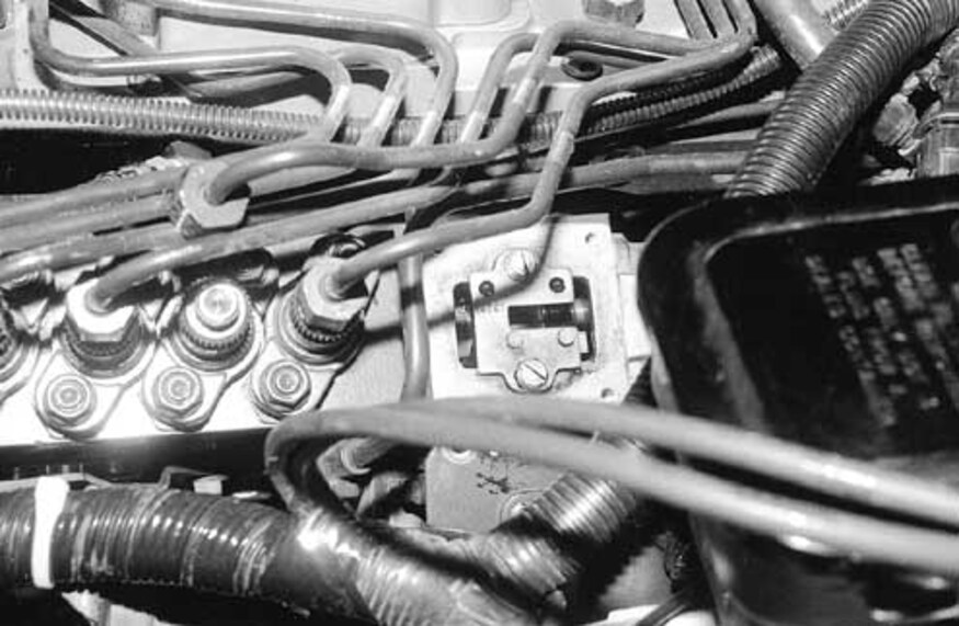
The amount of fuel that flows to the engine is controlled by a fuel-calibration cam located under a cover toward the rear of the pump (shown here with the cover already off). This is perhaps the trickiest part of the installation, so it’s important to follow the instructions exactly, including using scribe lines to mark the position of the cover so it can be reinstalled in exactly the same spot. Once the appropriate brackets and lines are out of the way, you’ll notice the factory-installed tamperproof screw, which has no head, in the upper lefthand corner. Use a chisel to make a slot in the screw suitable for a flatblade screwdriver. All of the cam-cover screws will be extremely tight, so investing in an inexpensive impact screwdriver may be helpful.
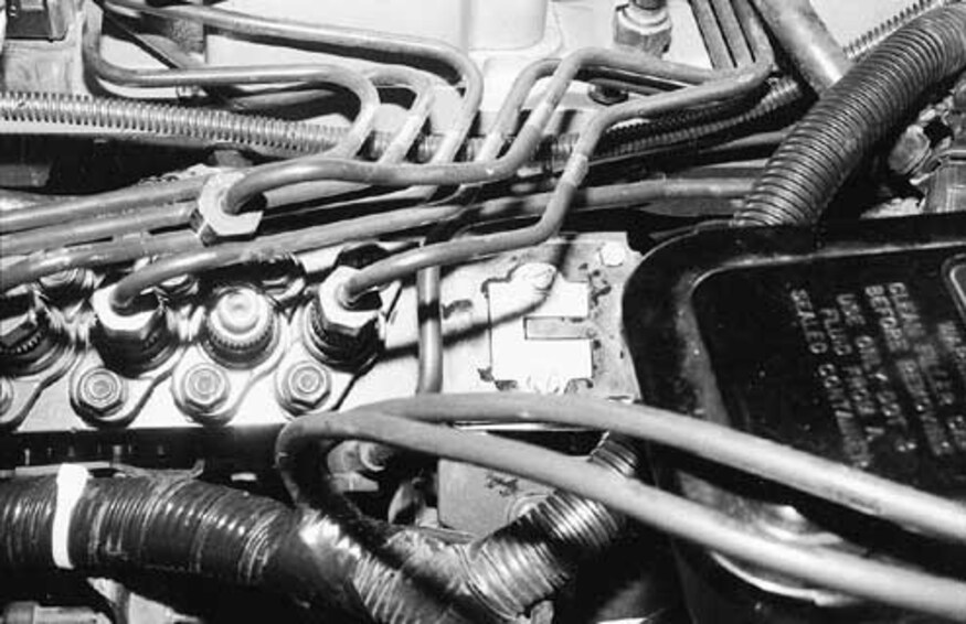
Don’t touch the fuel-calibration plate yet! Scribe two lines across the pump body to mark the exact position of the stock cam plate, then install the guide template supplied with the kit and butt the forward edge of the template (closest to the front of the engine) against the stock cam. Carefully take out the stock cam plate without moving the template and replace it with the one supplied in the kit, making sure it’s in the same place as the original. Once the new cam plate is secure, remove the template and reinstall the cam cover.
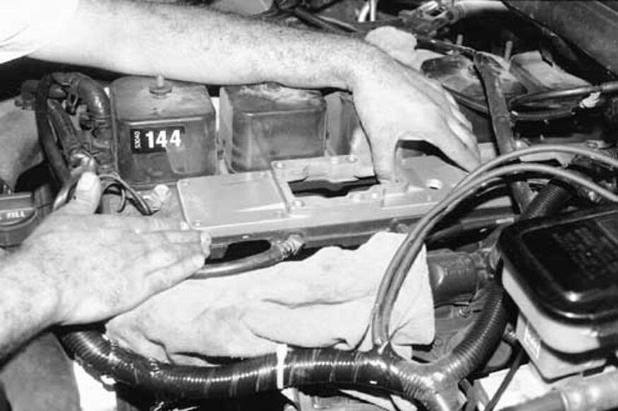
With the injector-pump work done, move on to the rest of the intake swap. Remove the lower intake (don’t forget to disconnect the wires for the heating elements), and clean the gasket surface. Install the new lower intake on the head, using a dab of Loctite on each of the retaining bolts. Install the rest of the hardware, including the air-temperature sensor and the fuel-filter bracketry. You can now separate the fuel-injector lines and install them on the engine, using the supplied clamp assemblies.
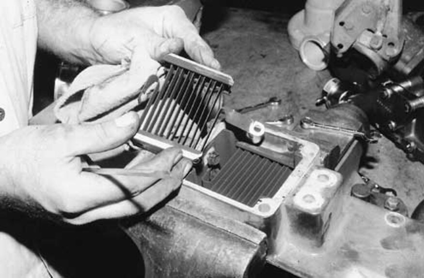
Instead of glow plugs in each cylinder, the Cummins engine uses two stacked heating elements located in the intake. These heating elements must be taken out of the original intake and installed in the heater housings of the new intake. It may be necessary to bend the leads slightly, but be careful not to damage them. Pay close attention to the order of the hardware, including the insulators and power-supply studs. The elements are separated from one another with the new intake, (one for each port) but there is no negative effect on starting capability.
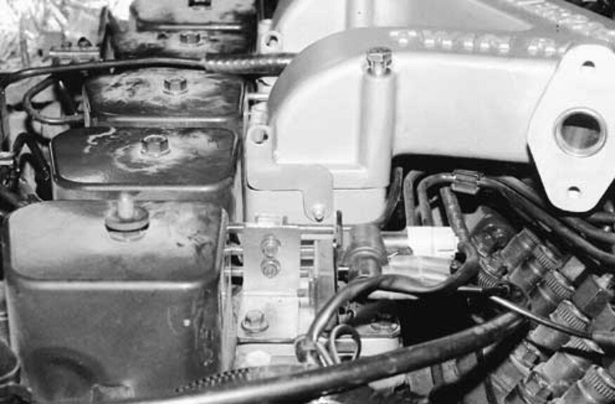
Install the heater housings on the lower intake followed by the upper intake, using the supplied gaskets. Again, pay close attention to the order of the fasteners and their washers. They’re designed to withstand the vibrations of the engine without loosening. The grounding straps for the heating elements must be carefully bent over the intake once it’s in place. On California models equipped with an EGR valve, install the metal gasket in the upper intake.
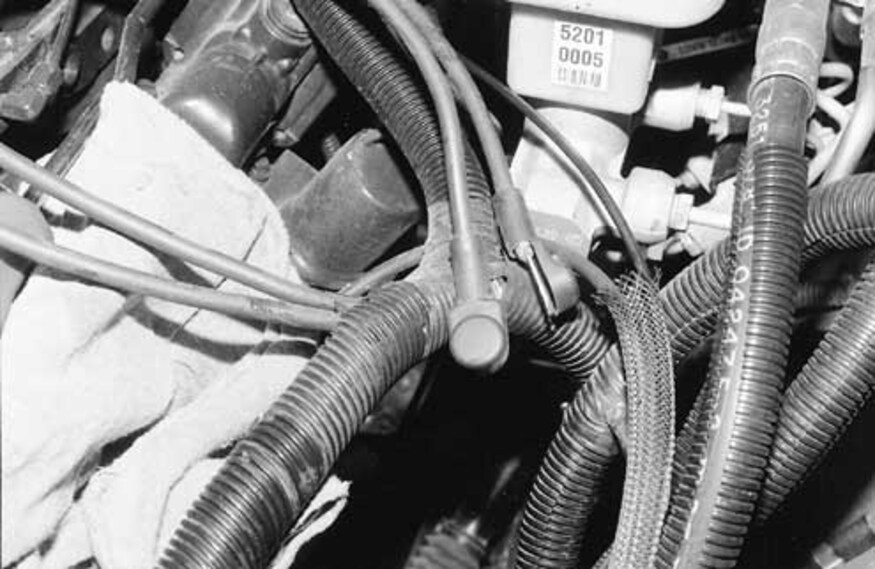
Since the heating elements are now in a different location, it’s necessary to separate the two power leads for the elements from the harness near the injector pump. No cutting is required beyond removing some electrical tape, and the harness can be left with its plastic loom intact. Use some electrical tape to keep the leads from separating from the harness further, and carefully route and connect them to the heating elements.
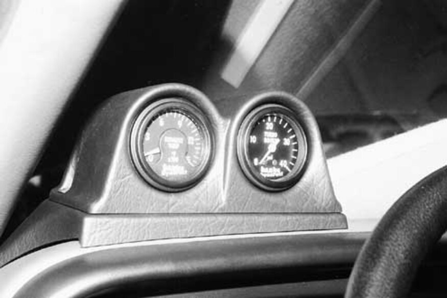
Now that the major work is out of the way, assemble the gauge cluster and place it on the dash. The cluster comes in and even has a texture to match the rest of the dash. Carefully route the tubing and wires for the boost gauge and pyrometer using the suggestions found in the installation manual. The lighting for the gauges should be connected to a headlight circuit, which can easily be found on the nearby fuse panel, and the ground wire can be attached to any solid metal bracket under the dash.
Reinstall any of the remaining parts and hoses that were taken out during the installation, and double-check your work to make sure nothing was missed. The final step is to purge the fuel lines of any trapped air. If the engine won’t start or runs poorly, loosen the banjo fitting above the fuel filter and use the push-button primer to free any air trapped in the main fuel line. If the engine still runs poorly or not at all, loosen the steel fuel lines one at a time and crank the engine until it appears that only fuel is escaping the fittings, then quickly tighten them. Use extreme caution during this procedure to prevent the high pressure fuel from puncturing your skin or spraying over a hot engine.