A Surplus 6.2L Blazer Gets a Banks Sidewinder Turbo Kit
Anyone over the age of 50 recalls the old “Jeep for $100” ads that used to be found in the back of such magazines as Popular Mechanics and Popular Science. What they failed to mention the Jeeps were in crates with some assembly required. However, there is still a great market for used military vehicles. And these trucks are usually inexpensive and most are diesel-powered.
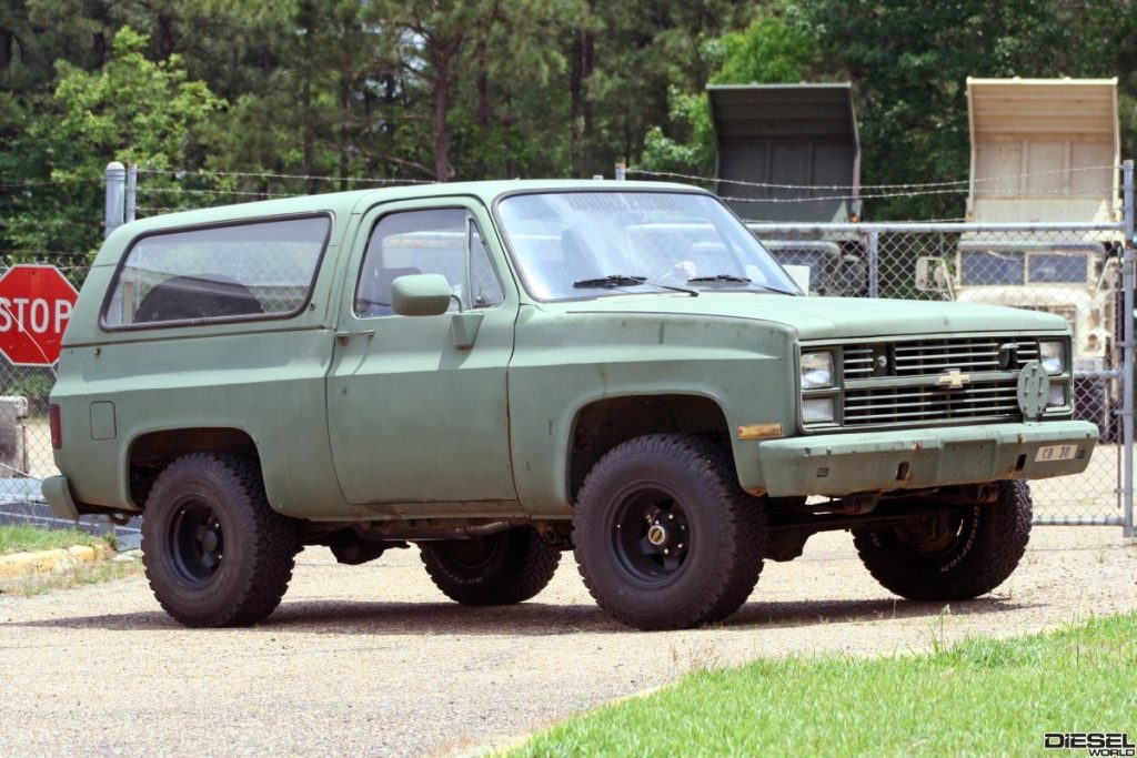
One of the most prevalent models out there is the old square body Chevrolet Blazer, complete with camo paint and the requisite 24-volt electrical system. It also comes with the 6.2-L diesel, which was not one of GM’s better diesel efforts. However, with a little tinkering and a turbo, the 6.2L in the Blazer platform can be a great entry-level diesel vehicle.
We know you’ve noticed more and more military surplus vehicles on the road these days, and the reason is that as the US military replenishes its fleet of domestic vehicles with more capable and technologically advanced units, they have begun ‘retiring’ these older vehicles such as the 1984 Blazer you see here.
Our Budget Blazer Buy We picked up this camo beauty for $2500.00 from the on-line auction site www.govliquidation.com. They come in various states of repair, and disrepair, from bases all across the country. Some never left the states, while others saw front line duty.
Dubbed by the military as an M1009 CUCV (Commercial Utility Cargo Vehicle) our find is much better known as a Chevrolet K5 Blazer. The CUCV Program of the late `70s and early to mid-`80s called for the US military to find a cost-effective vehicle to bridge the gap between a full-blown tactical vehicle and the less expensive civilian vehicle.
Dodge initially supplied vehicles, but by the early `80s, GM had become the supplier of choice. In order to meet military spec, these units were all equipped with the 6.2L diesel engine and used a 24-volt electrical system. It was actually a hybrid 12/24-volt system that used 24-volts under the hood, complete with dual 100 amp alternators, the mandatory NATO slave receptacle for jump-starting any NATO vehicle, and hookups for military radios. The rest of the truck was 12-volt.
Like
any man who sees potential where others see a lost cause, (mostly wives and
girlfriends) and potential unwanted yard art; I saw the makings of a very
capable multi-purpose built rig. A well thought out and executed build
could result in a competent off-road trail rig, a fun weekend driver and a
capable tow rig to boot. The full-size capacity and ability to tow makes this a
unique build as opposed to your everyday Jeep.
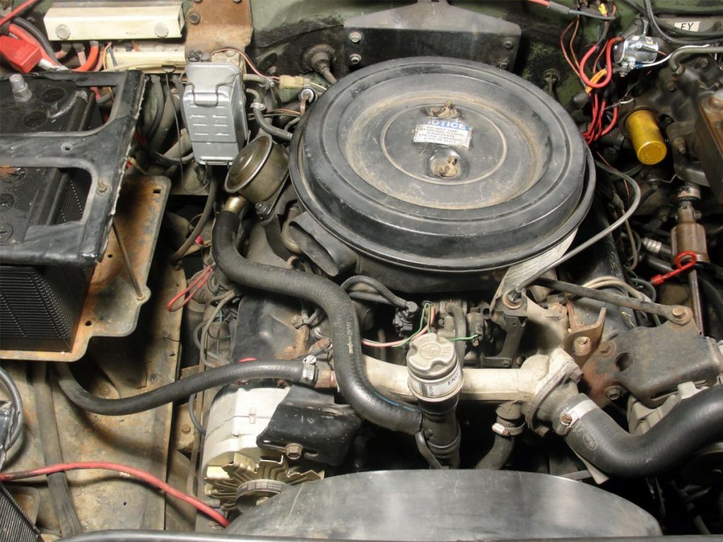
Weak 6.2L Diesel To accomplish this meant immediately addressing the power issue, or lack thereof. While the 6.2L is a solid and reliable power plant, it lacks the power to cruise highway speeds with traffic, let alone tow. The odometer only showed a little over 4K miles, which doesn’t mean “everything” as those 4K miles could easily translate into 400K hours. But upon further inspection, everything seemed to be in good working order requiring nothing but a new set of glow plugs for the old 6.2L to breathe life again.
Options for adding power are pretty limited; a complete engine swap or adding a turbo. While the thought of a well-built Cummins or a late-model Duramax makes me smile, the added expense, labor, and down-time involved to do the swap kinda kills the low-budget them we have for this truck.
The Banks Solution When someone says ‘turbo’, the name Banks is usually not far behind. When you’re the first to do something, people remember your name. Gale Banks was a true pioneer in the diesel performance aftermarket we all enjoy today. Much of his personal and business success can be traced back to being the first to truly address the lack of power in the 6.2L.
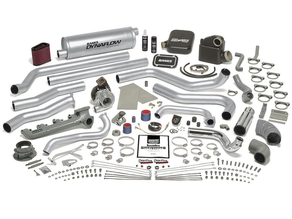
Believe it or not, Banks still offers their Chevy Sidewinder kit for the 6.2L and told us it would be almost a drop-in for the military K5. So I ordered up the needed Banks Turbo kit (Bank’s Chevy Sidewinder #8293), Read through the instructions (several times), and called the Bank’s tech line with some questions. I also double-checked the parts list & tools list, gathered up what was needed, along with some confidence, and proceeded to get started.
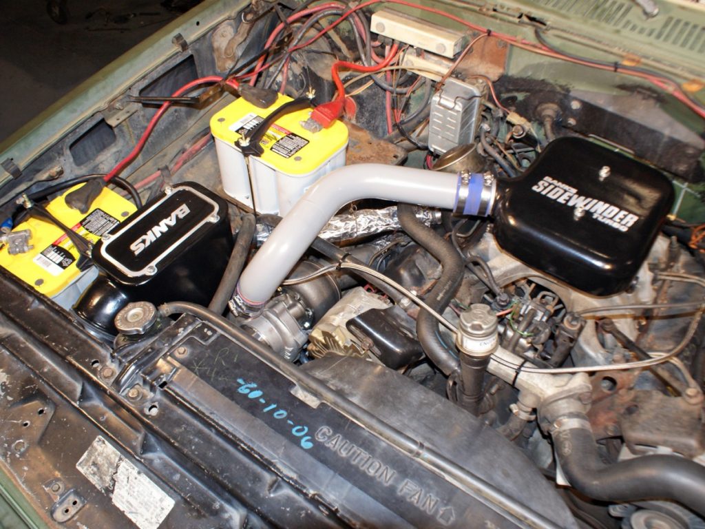
The kit comes complete, and we mean complete with everything to turn the non-turbo 6.2L into a turbocharged diesel. The kit includes a new exhaust manifold and exhaust system, new air intake and high-flow air filter, and all the necessary hardware to make the conversion a bolt-on deal. The installation was a straight forward process although there are always issues when working on an older ride (factory bolts break during disassembly, taps are needed in the hardest to reach areas, radiator drain breaks, missed supper again, etc.). However, the end results were a much more powered vehicle with the added modern technology of turbocharging.
If you’re in the market for an entry-level diesel truck and don’t have a lot of money to spend, consider one of these military beauties. Plus, the Banks Sidewinder kit adds a lot of power and driveability to make the experience that much more fun.
SOURCES:
Gale Banks Engineering 546 Duggan Ave Azusa, CA 91702 800-601-8072 www.bankspower.com
LMC Trucks 15450 West 108th Street Lenexa, KS 66219 800-541-8525 www.lmctrucks.com
OPTIMA Batteries, Inc. 557 North Green Bay Avenue Milwaukee, WI 53209 888-867-8462 www.optimabatteries.com
AutoZone 123 South Front Street Memphis, TN 38103 800-288-6966 www.autozone.com
photo
captions:
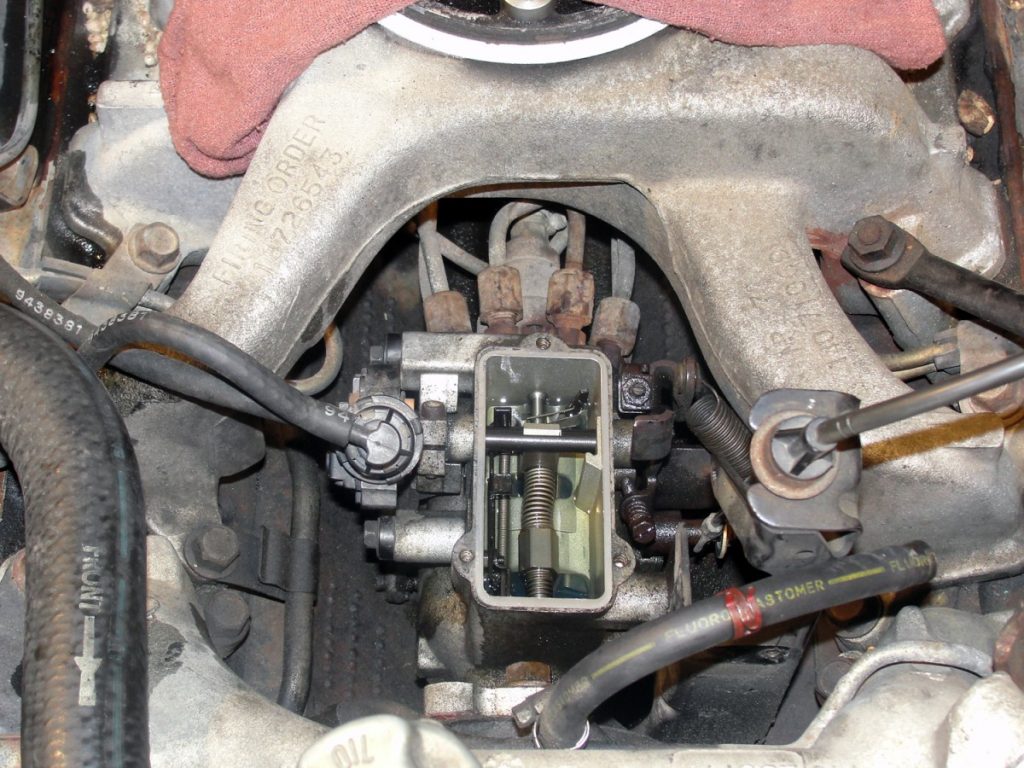
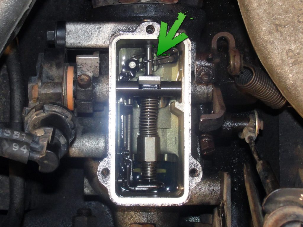
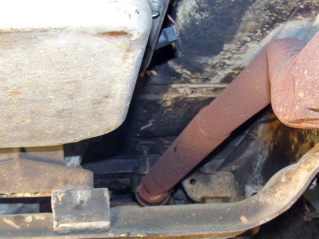
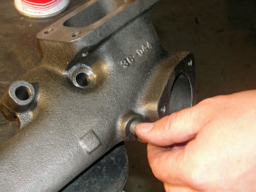
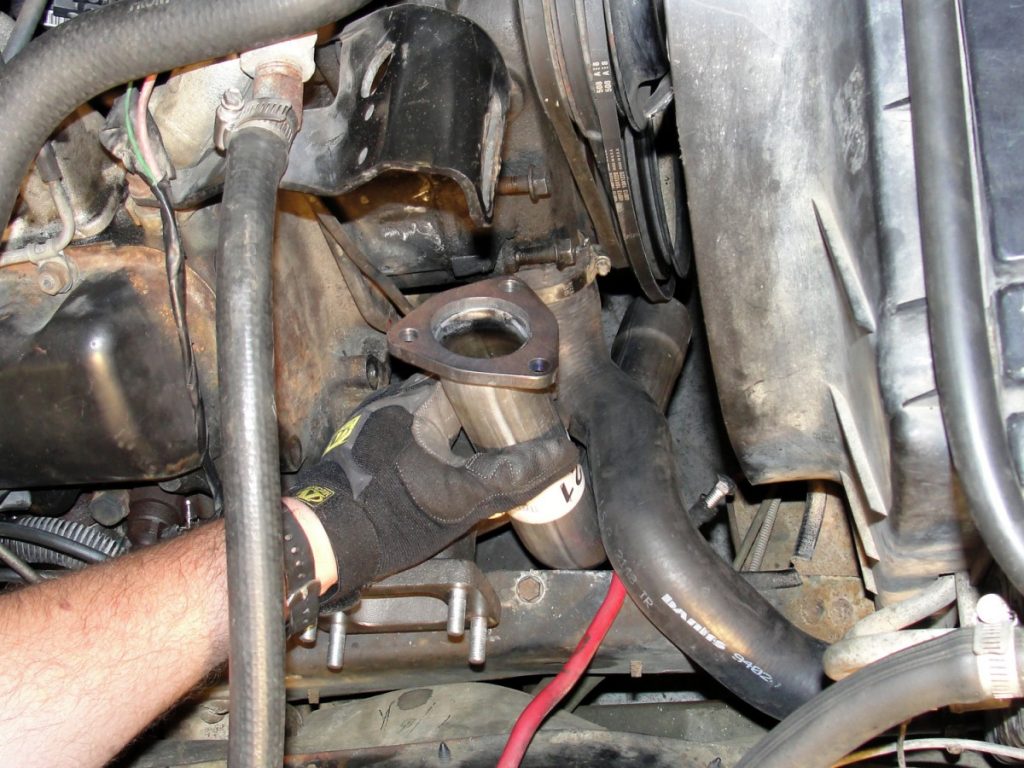
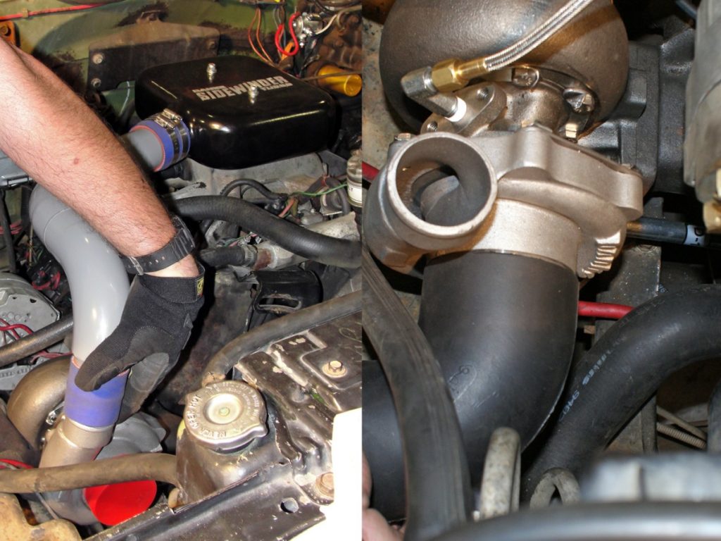
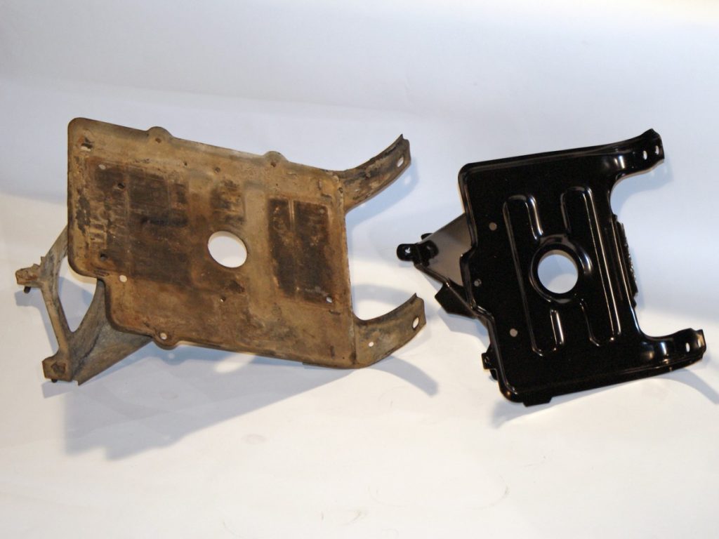
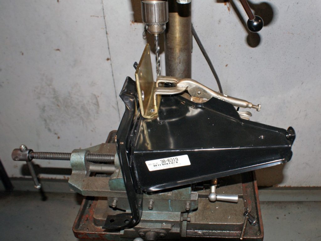
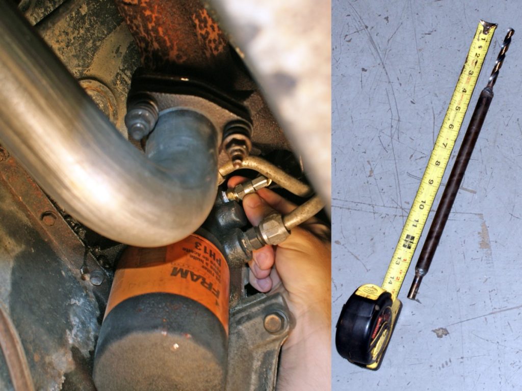
A great entry-level diesel vehicle that is found readily on the government auctions is that mid-80s K5 Blazer with the 6.2L diesel.It ain’t pretty, and sure looks a lot like a small-block Chevy gas motor, but the 6.2L in our auction find supposedly only had in our auction find was a runner.The Banks Sidewinder kit for the 6.2L diesel comes complete with everything you need for the swap including new intake and exhaust manifold and a detailed instruction book. The first step with any installation like this is a thorough read-through of the instructions followed by a check-off of all the parts from the parts list.Disassembly begins by disconnecting the batteries, removing the air cleaner, air cleaner brackets, mounting studs, inlet gasket, and the crankcase vent tube assembly. After covering the intake opening with a clean rag and cleaning the area surrounding the injection pump and pump itself; the fuel rate must be turned up. This is accomplished by removing the top of the injection pump and locating an Allen head screw visible through an adjustment slot in the bottom of the pump.To access the adjustment screw, the pump cover is removed. To make things easier, we ended up siphoning some of the diesel from the pump bowl. The governor spring assembly is then removed by removing the guide stud and sealing washer located at the rear of the pump. After removing the spring assembly, the adjustment slot is clearly visible. If you cannot see the adjustment screw in the slot, the engine must be rotated by hand to bring the Allen screw into view. Once visible, use a 5/32” Allen wrench to rotate the screw 1/4″ turn clockwise. The screw turns tight so be sure you have a good bite before making the adjustment.After adjusting the injector pump, you can re-install the governor spring assembly, sealing washer and guide stud, re-fill the injector pump with clean diesel and re-install the pump cover. New mounting studs for the air chamber/plenum are then installed with 5/16” spacers between the stud and the intake manifold. Two 3/4” caps and spring clips are used to cover the vent nipples left open by removing the crankcase vent tube assembly. A new gasket is provided for the air chamber to intake surface and the air chamber is then installed using sealing washers and locknuts. The air chamber is pre-drilled and tapped for a boost gauge fitting, the fitting or a plug must be installed.The exhaust can now be removed. You must retain one exhaust to manifold flange and hardware for re-use as well as one doughnut gasket. In our case both doughnut gaskets were pretty much shot, so we picked up a new one anyway. (ref: rusty underneath pipe)The fuel lines are then disconnected at the lift pump. The lift pump and factory spacer plate are removed. The fuel pump rod will want to slip out, but a good coating of grease will help keep it in place while the mounting surface is cleaned and a new spacer plate is installed before re-attaching the lift pump. The new spacer plate contains a tube used for the return of oil from the turbo.The right side glow plugs are then removed as well as the factory exhaust manifold. Twenty-six years can create one incredible bond as the studs were not the easiest to remove. To gain greater access the batteries and battery trays were removed. Despite the additional clearance one exhaust manifold bolt still had to be cut.After removing the factory manifold, a bolt was welded to what was left of the stud and the bolt was removed.
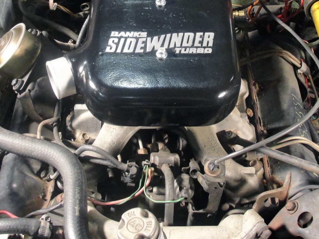
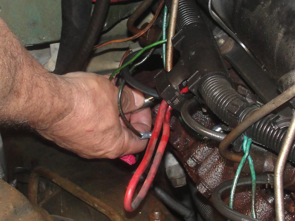
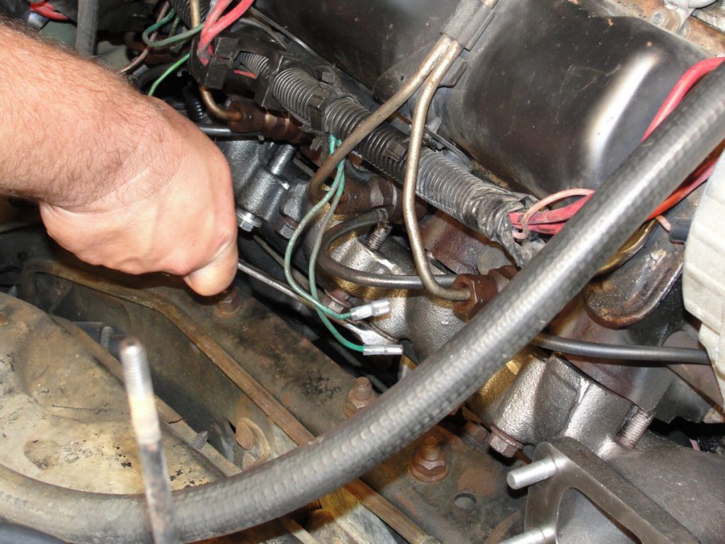
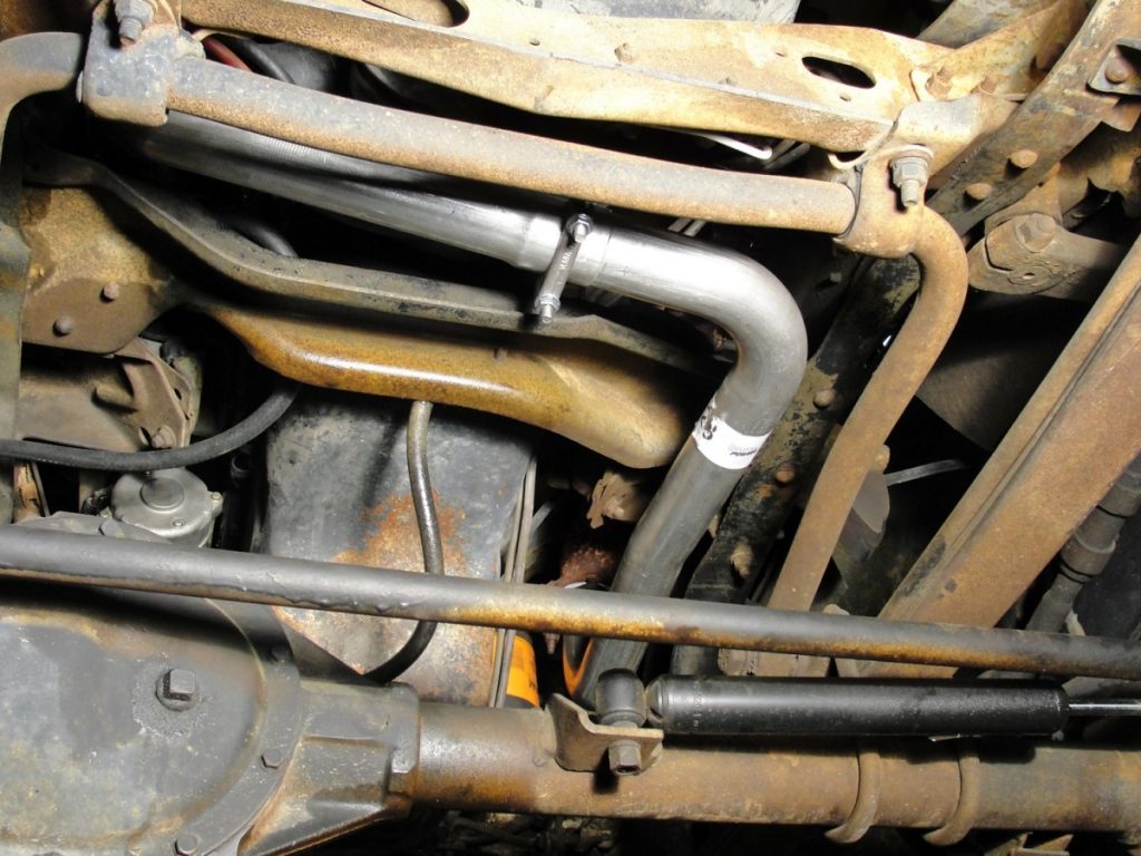
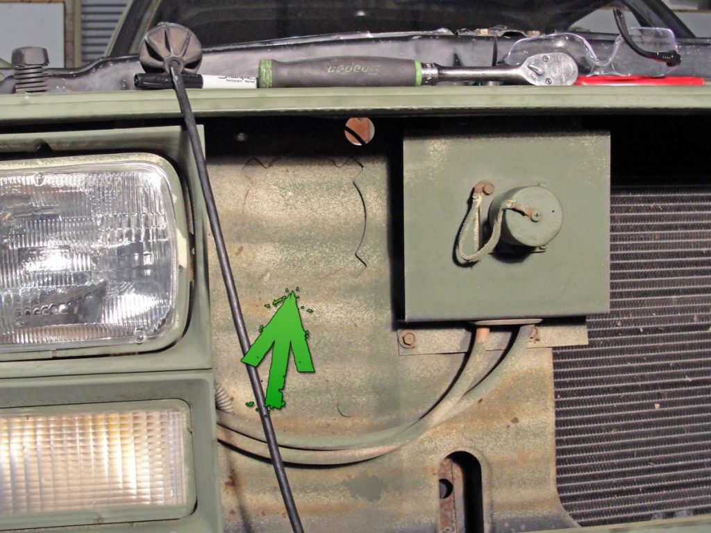
The coolant is then drained from the radiator so the new lower radiator hose can be installed. There is a ground wire to frame attachment bolt that must be relocated to prevent chafing of the new hose. Once the new hose is installed, the radiator can be re-filled. (photo ref: red wire left, black hose right)
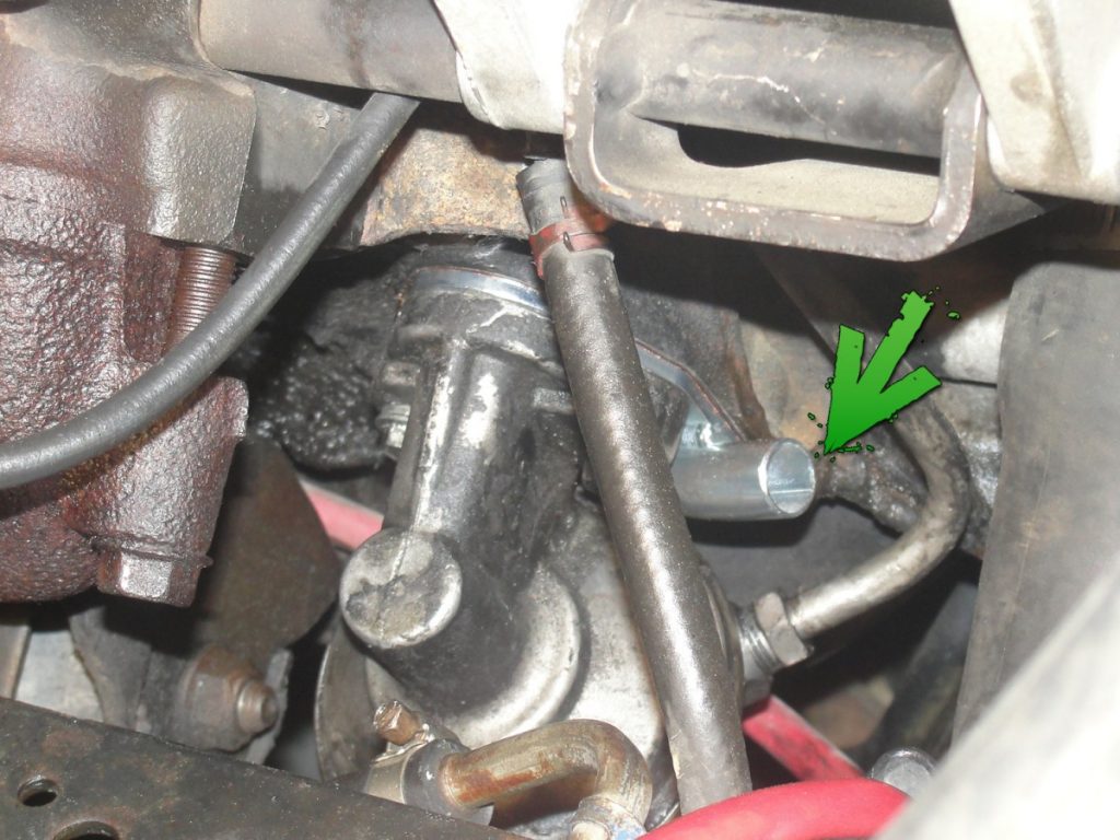
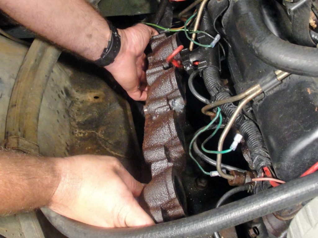
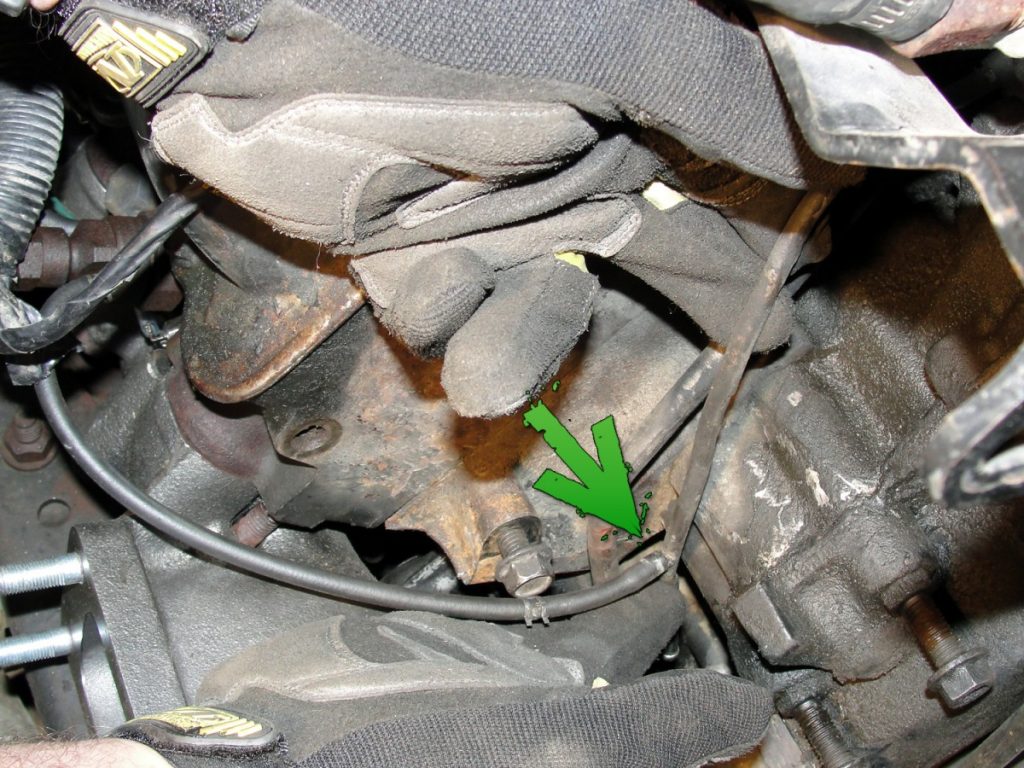
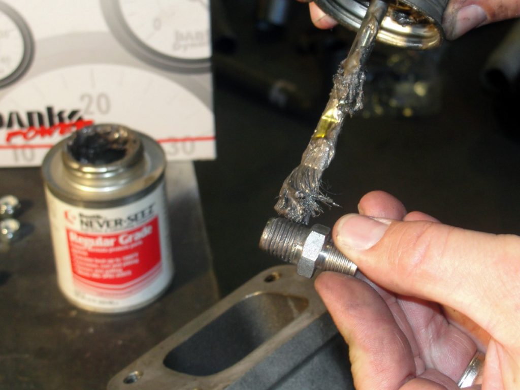
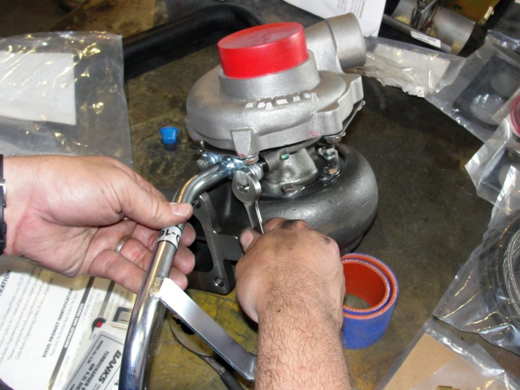
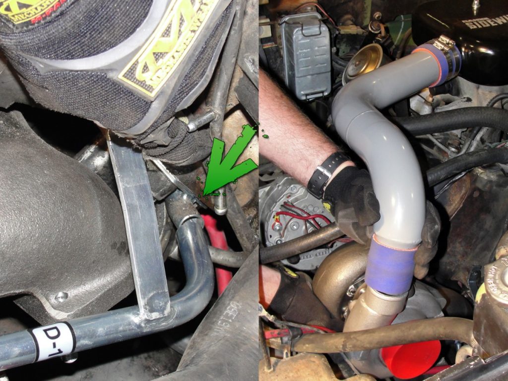
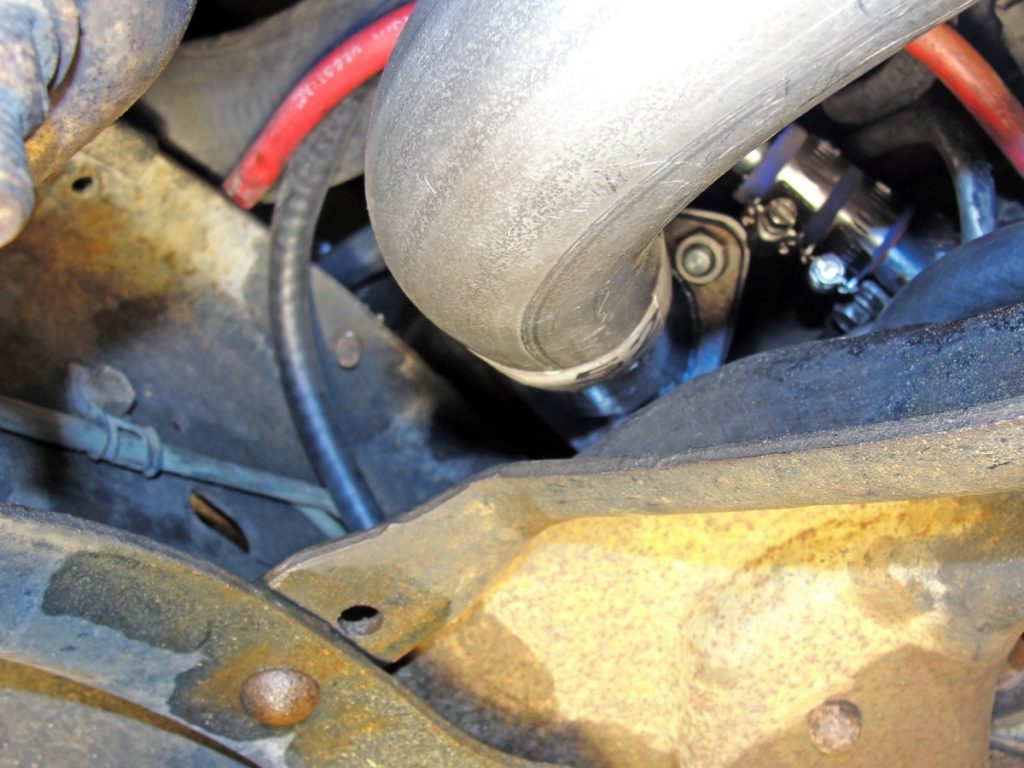
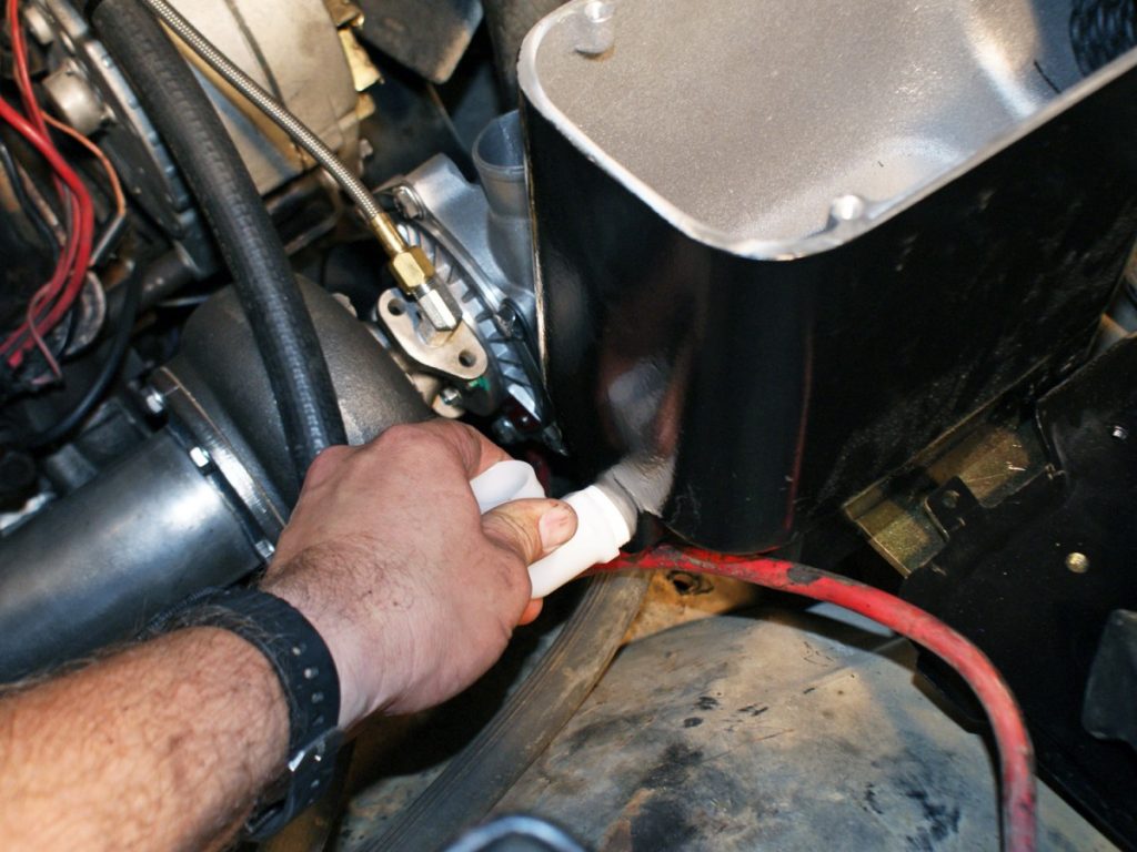
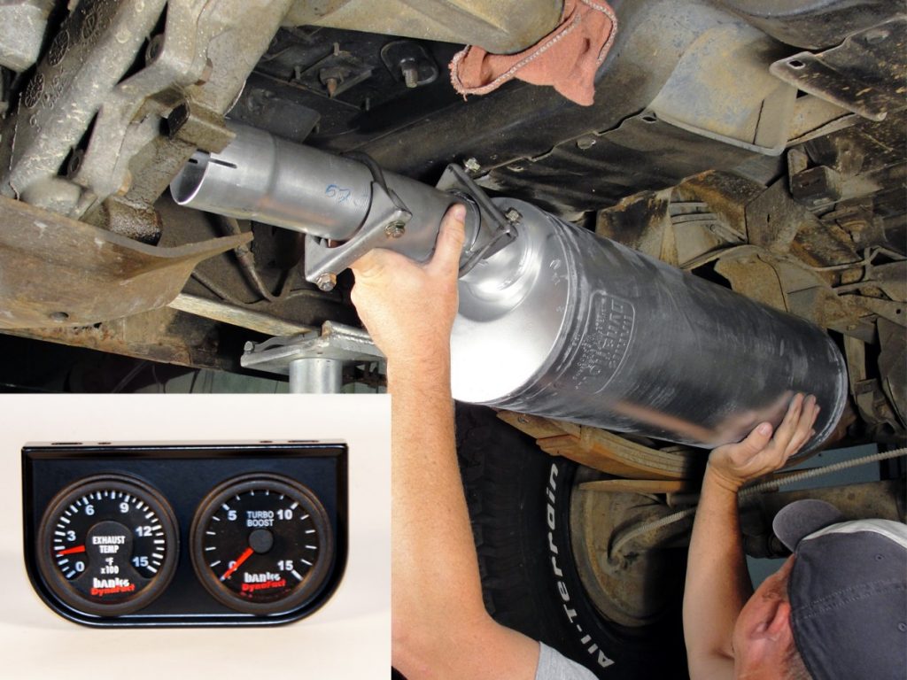
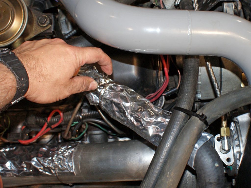
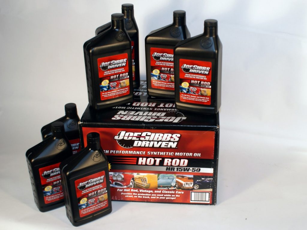
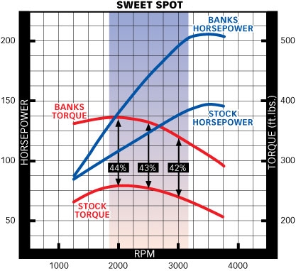
The return fuel line to the injector pump is located on the front side of the right cylinder head. This line must be carefully bent and re-routed to keep it as far away as possible from the new exhaust manifold. As you can see, we removed the right-hand alternator to gain more access to the line.A pyrometer probe adapter is installed in the new exhaust manifold using anti-seize on the threads. The new exhaust manifold can then be installed using the original mounting bolts. The Banks instructions recommend that the bolts should be inserted into the manifold and then secured using rubber bands until the bolts are started. We thought we knew a better way and didn’t need the rubber bands. After several failed attempts due to bolts falling out and a good bit of cursing, we can say from experience that a small package of rubber bands is money well spent! Once the manifold is in place the glow plugs can be re-installed and the glow plug wiring and fuel return lines between the injectors should be routed up and away from the manifold. (photo ref: rubber cement)A drain tube used to connect the new lift pump spacer plate can now be mounted to the center bearing assembly of the turbo. (photo ref: hands, turbos w/ red caps)The turbo is then temporarily mounted to the exhaust manifold and the center bearing assembly is rotated so that the drain tube aligns with the spacer plate tube on the lift pump. Lightly snug one of the six bolts on the turbo to secure the position of the turbine housing. The boost tube is then temporarily installed between the air chamber and plenum. The turbo compressor housing is rotated to align with the boost tube and a bolt tightened to secure its position as well. The boost tube and turbo are then removed and all twelve bolts are tightened and pre-installed locking tabs are folded into place to secure the bolts.The new exhaust cross-over pipe is dropped into position and the new head pipe is positioned between the engine end the right frame rail.The turbo can now be installed. Use a piece of blue silicone hose and hose clamps to attach the turbo drain tube to the lift pump spacer plate and tube. The turbo is secured to the exhaust manifold using stainless collet locknuts. After the turbo has been installed, the boost tube can be re-installed.Bolt the exhaust pipe to the new manifold using the supplied gasket and stainless collet locknuts. A heat shield is positioned on the head pipe to help protect the lift pump from direct heat. The factory floating exhaust flange is slipped on the new cross-over pipe and the new doughnut gasket is installed in the manifold before installing the cross-over pipe between the new head pipe and the left side exhaust manifold. The cross-over pipe slips into the new head pipe and is secured using a 2” exhaust U-clamp. The head pipe and gasket is now mounted to the turbo as well.This is a good time to make sure all fuel lines have adequate clearance from the new exhaust head pipe. In this instance, all the fuel lines required re-routing, but Banks includes plenty of new fuel hose to allow for this.The new airbox assembly gets its fresh flow of air through an inlet duct in the radiator support. If not removed (as in this case) the duct is pre-punched and requires removal before you can install the plastic inlet hood.When we started, we weren’t sure if there were any differences in the military version that would present any issues or require modification. In the end, there were only two such issues. The first of which is a result of the 24V charging system. On a normal everyday K5 you would find one battery on each side of the vehicle. However, ours has dual batteries located on the right side of the vehicle. The New Banks air filter housing mounts to the front right battery tray, however as you can see in the comparison, the battery tray used in the military truck is considerably larger than those normally found. This meant we must heavily modify the existing tray, manufacture a new one or replace it with a tray from a civilian style K5. Looking at how the box mounted quickly sent us searching for a replacement. Within minutes we had located what we needed at www.lmctrucks.com. (photo ref: two parts on table)The airbox mounting bracket mounts to the battery tray supports and requires drilling. Using the bracket as a template, we drilled the mounting holes and installed the new tray, bracket, airbox and filter assembly.After mounting the airbox you can now install the connection hose between the anti-depression valve and the airbox. The hose hooks to the airbox via a plastic nipple screwed into the rear of the box. We had to modify the supplied hose as the anti-depression valve is located above the right valve cover rather than over the alternator like the civilian trucks. We used a piece of stainless tubing and some hose clamps to extend the hose the correct distance.The turbo receives oil from the engine from an oil port located just above the oil filter. Fittings and a stainless steel braided hose are provided to make the connection. Beware: The port is not easily reached! The 1/4” square drive factory plug can easily be stripped, Oops. After stripping the plug, we had to make a custom 11/32” drill bit long enough to reach the plug so we could get a remover tool in the correct position for the plug to be removed. Once out, installing the fittings and routing the hose was a snap. The hose should be left loose where it connects to the turbo to ensure that oil is flowing prior to starting the engine. (photo ref: tape measure)We were ready then to install the rest of the exhaust system as well as the pyrometer and boost gauges. The Banks exhaust system uses preformed pieces that slip fit into one another and exhaust U-clamps to secure them. The exhaust system fit easily and literally fell right into place. Installing the Banks pyrometer and optional Boost gauge was as straight forward as the exhaust system. A dual gauge faceplate and all connectors were provided, making installation quick and easy.Prior to reconnecting the batteries, it’s time to give everything a final double-check. All fuel lines and wiring should be checked to ensure adequate clearance from heat sources. Banks provides some heat shielding that can be installed at this time as well.Finally it was time to re-connect the batteries and turn this baby over – However, the factory batteries which looked to be out of a mid-`60s John Deere combine were way too large to fit the smaller battery tray we installed with the new airbox. We needed 2 smaller yet amped up juice boxes to fit the spots. Optima Batteries’ offer a wide selection of sizes, side & post mounts, and various juice options that gave us the perfect fit for our requirements. We opted for a pair of deep-cycle Yellow Top Optima batteries from AutoZone. The Yellow Top Optima’s have excellent cranking power, are vibration resistant and are known to cycle extremely well.Now we were ready for the initial run. There was only one thing left to do and that was change the engine oil. Instead of just yanking our favorite brand off the shelf at the local store we had heard that Joe Gibbs Racing has released its own brand of premium oils, so we decided to order some up and give it a try.After the oil change, we were ready for the initial run. The engine cranked right away and didn’t take long to purge any remaining air from the fuel system. As far as results are concerned, Banks claims an increase of up to 60+ horsepower and 115+ lb-ft torque.