


FMEA: What is it and what benefit does it provide the customer
FMEA: What is it and what benefit does it provide the customer?
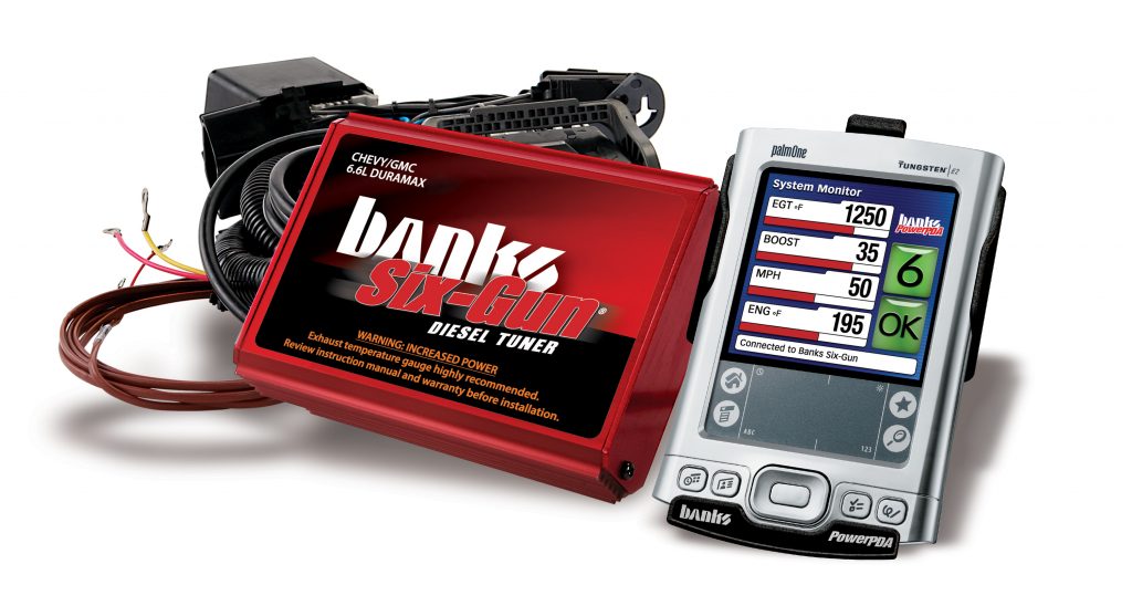
Banks’ electronic products offer customers exclusive ActiveSafety™ redundant design. ActiveSafety is an easier way of saying what Banks engineers refer to as Failure Modes Effects Analysis, or FMEA for short. This paper explains what FMEA is, how it makes our products different and what benefit it provides to our customers. I’ll warn you up front though, it gets a little deep, but if you’re interested, it is worth the read.
FMEA is an acronym for Failure Modes Effect Analysis. This is really a design process and standard that Banks applies to its electronic products. In order to understand this, it’s important to understand how late model vehicles are designed from an electronics standpoint.
The Modern Vehicle
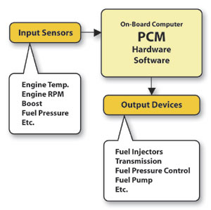
As you probably already know, newer vehicles are a marriage between highly sophisticated electronics and mechanical devices. The heart of the electronic system is an on-board computer system that rivals the power of your desktop PC, but built rugged enough to withstand the harsh automotive environment. The on-board computer, usually called a Powertrain Control Module (PCM), literally controls the operation of the engine and transmission. To do this the PCM is connected to numerous sensors on the engine and transmission that monitor such parameters as engine speed, temperature, gear position, throttle position, manifold pressure and a whole host of other items. These are referred to as inputs to the PCM. In order for the PCM to control anything it must have some type of output actuator that performs the actual control. For instance, the PCM controls the fuel injectors to precisely control the amount of fuel delivered to the engine. Every item the PCM is responsible for controlling must have some type of output actuator. On a newer vehicle it’s not uncommon to have over 15 input sensors and 20 output actuators. (See Figure to Left)
Hardware & Software
Just like your home PC, the vehicle computer has software that controls how it operates. Without this software the computer would just be a bunch of electronic parts inside a box, without function and unable to perform any tasks. The software on your vehicle is very sophisticated and contains thousands of lines of code. This code is flashed or burned into the microprocessor in the PCM. It’s this code that controls how much fuel is delivered, when and at what speed the transmission shifts, etc. In many respects it has to be much more reliable than the software on your PC. You wouldn’t exactly appreciate your PCM locking up on you as you were merging on the freeway. Because of this, manufacturers spend millions of dollars testing and debugging software before it is released for production. Even then it is sometimes necessary to update the software after the vehicle is in the field to correct or improve vehicle operation. This is commonly referred to as a “reflash.”
On-Board Diagnostics
Events happen very quickly in the world of automotive electronics. The computer system must execute several thousand lines of code in a fraction of a second. A fuel injector may only need to be held open for a few milliseconds to deliver the proper amount of fuel. If a sensor or actuator fails it can wreak havoc on the system and possibly render the vehicle disabled. Because of this, one of the most important functions of the PCM is to perform diagnostics on the vehicle. This occurs continuously as soon as the vehicle is turned on. It’s here where you really begin to appreciate what goes into one of these vehicles. The basis for these diagnostics is a control loop that uses a sense and control strategy. The computer senses a parameter and then controls something based on that parameter. But what happens if the sensor goes bad, or just becomes unplugged? How can the PCM discern the difference between a defective sensor and actual output value? Two strategies are employed to accomplish this: Design Strategy and Comparative Analysis.
Design Strategy deals with the actual design and output characteristics of sensors used on your vehicle. For this discussion we’ll talk about a boost sensor. Most analog sensors on the vehicle are capable of output voltages from 0-5 volts. However, the design strategy ensures the actual sensor range is usually between .5-4.5 volts. The voltages below .5 volt and above 4.5 volts are considered reserved and are considered failures by the PCM. The PCM knows that if these values are seen, the sensor could be unplugged, shorted or may have completely failed. In this case the PCM would ignore this input and may use the last known good value or try to calculate an estimated value based on inputs from other sensors.
Comparative Analysis is a software feature that compares sensor values to each other to determine if the system is functioning properly. In the example above, the Design Strategy wouldn’t detect that the sensor is out of range if its output was within the .5-4.5 volt operating range. Let’s assume that the boost sensor is designed to provide 3.25 volts at 15 pounds of boost but the actual output is 2.00 volts because there is a leaking hose near the sensor. The 2.00 volts is within range but still not correct for the actual boost present. The PCM could detect this by comparing the measured boost value to a calculated value which is determined by analyzing and comparing to other engine parameters. For instance, if the PCM measures that the engine is operating at 2,500 RPM and is at wide-open throttle, it could calculate an “expected” boost value. It would then compare the measured value to determine if it is in range. In this example the PCM may calculate the expected boost value to be between 3.00-3.5 volts. If the measured value is 2.0 volts the PCM would consider this out of range and use the calculated value instead.
In either case, if the PCM determines that the output of the boost sensor is incorrect, it will set a Diagnostic Trouble Code and illuminate the Check Engine Light to indicate a failure to the driver. There are hundreds of diagnostic codes that help the technician diagnose the vehicle. Each code represents a specific type of failure. The codes are stored in the PCM’s memory and can be retrieved by the technician using a diagnostic scan tool.
As you can see, the manufacturer has gone through a lot of trouble to ensure that your vehicle is as reliable as possible. It contains sophisticated diagnostics and is designed to constantly monitor itself to detect any anomalies or failures.
Aftermarket Products & FMEA
There are numerous aftermarket products out there for your vehicle. At first glance they all may look like the same type of electronic control module even though they may have been engineered in a completely different way. First, we need to understand what these products do and how they affect the operation of the vehicle. Typically, these modules install in-between the PCM and its sensors and actuators. If the product was not designed properly, it becomes the weak link in the system and literally undoes everything the manufacturer has done to make the vehicle reliable. This is where FMEA comes to life. FMEA is Banks’ design requirement to maintain the integrity of the vehicle’s electronic control system.
As a result of this design requirement, it is necessary to implement numerous safety mechanisms divided into two layers — a hardware layer and software layer.
Hardware Layer of FMEA
The engineering department at Banks analyzes the vehicle and designs its hardware to integrate seamlessly with the vehicle’s existing electronics. Our design process ensures that our electronics do not adversely affect the vehicle in any way. The hardware is also designed to monitor itself and provide an automatic bypass which restores the vehicle to factory condition should something malfunction. This function is accomplished by incorporating many watchdog circuits to continually watch the operation of the control module. If the module loses power or in the unlikely event of a component failure, this watchdog will place the module into a mechanical bypass. This functionality is critical when installing any type of aftermarket electronic module since the module will be required to regenerate the vehicle’s sensor signals to the vehicle’s PCM. It only makes sense that the aftermarket product be as reliable or more reliable than the vehicle’s existing electronics.
A good example of this design is presented in the control module offered for the Chevrolet Duramax engine. This module controls injection timing, fuel injector pulse width and fuel rail pressure. Our module contains two microprocessors for this application. Each microprocessor is responsible for separate tasks; however, both processors must continually communicate with one another and report normal functionality. In this case the processors watch each other. If either processor goes off-line, the other processor will instantly restore the vehicle to stock form. In addition to this, a separate circuit continually monitors both processors’ activity, and if it detects any abnormal operation it can automatically restore the vehicle to stock, as well. It is this redundant level of design that sets the Banks product line apart from the competition.
Banks also uses the most sophisticated components, manufacturing process and testing procedures to ensure product quality. Products are fully tested prior to shipment using the latest test equipment. In fact, Banks uses LabView, the same testing and simulation software that is used by NASA, JPL and other prestigious organizations. This significant investment in hardware and software is another advantage provided by Banks products.
Software Layer of FMEA
Just like the factory computer systems, Banks control modules include advanced diagnostic features. Our software is designed to continually monitor and diagnose itself. In the event of a malfunction, a diagnostic code is set which can help you pinpoint the problem. Diagnostic codes can be read by viewing the number of LED flashes on the side of the module. This feature is something you won’t find on competitors’ products.
Our software also monitors vehicle parameters. Our Duramax product monitors automatic transmission parameters and if it detects slippage, it will automatically derate power to compensate, thereby preventing transmission damage. If you install the optional Speed-Loader* with the thermocouple, our module will automatically derate power if exhaust gas temperatures become too high. Our software also detects when the Torque Converter Clutch is locking up and derates power for a fraction of a second to reduce transmission wear.
The Banks Difference
Modern vehicles are a complex synergy of electronics and mechanics. The aftermarket products you choose should not compromise this and should be engineered to the same or higher standard. Although a competitor’s electronic box may work, it may not be engineered to the same standard as a Banks product.
*Please note: The Speed-Loader module mentioned in this article is no longer offered as a separate component. Call Banks Power at (800) 601-8072 to find out what specific products are made for your vehicle.