
Airflow – The Secret To Making Power
The basics of making power are simple. It begins with airflow, but it doesn’t end there.
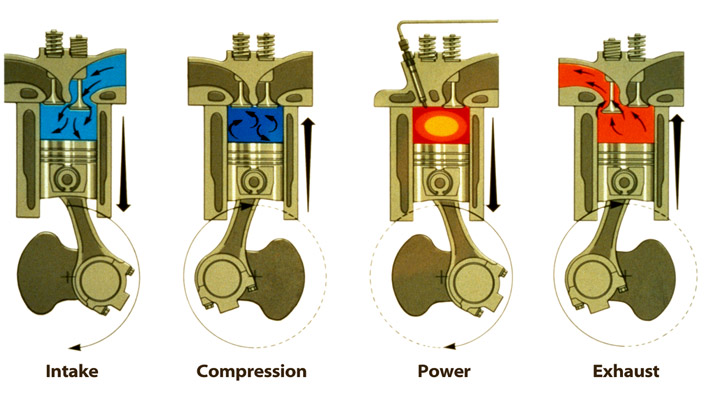
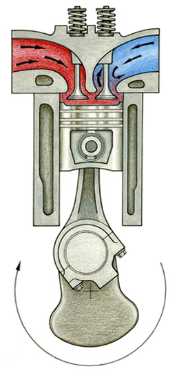
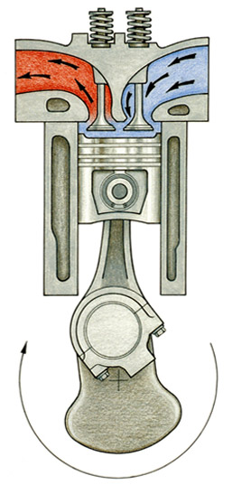
Suppose you have a 300-cubic-inch gasoline four-cycle engine. Most of you know how an engine works, but as a simple review, a four-cycle engine has an intake stroke to draw the air/fuel mixture into the cylinder as the piston moves down the cylinder bore, followed by a compression stroke during the following upward movement of the piston. These first two strokes occur during one revolution of the crankshaft (see Fig.1). On the next revolution of the crankshaft, the power stroke occurs as the air/fuel mixture burns pushing the piston down. The following upward movement of the piston is the exhaust stroke. Two revolutions of the crankshaft, four distinct cycles – it’s the basic Otto-cycle piston engine.
By its very design, this means our 300-cubic-inch engine takes in 300 cubic inches of air every two revolutions of the crankshaft. Now here’s the interesting part. It does this whether the throttle is open or closed. But wait, you say. The engine takes in more air when the throttle is open. And while it is true that more air mass flows into the engine when the throttle opens, the engine’s size, or displacement, never changes, so the only actual difference is the density of the air that fills that displacement.
When the throttle is closed, very little air mass flows into the engine, so that small amount has to expand to fill our 300 cubic inches. Thus, the air will be of very low density. As the throttle opens, more air mass can flow in to fill the engine, and the density will increase. This is often called the “charge density”.
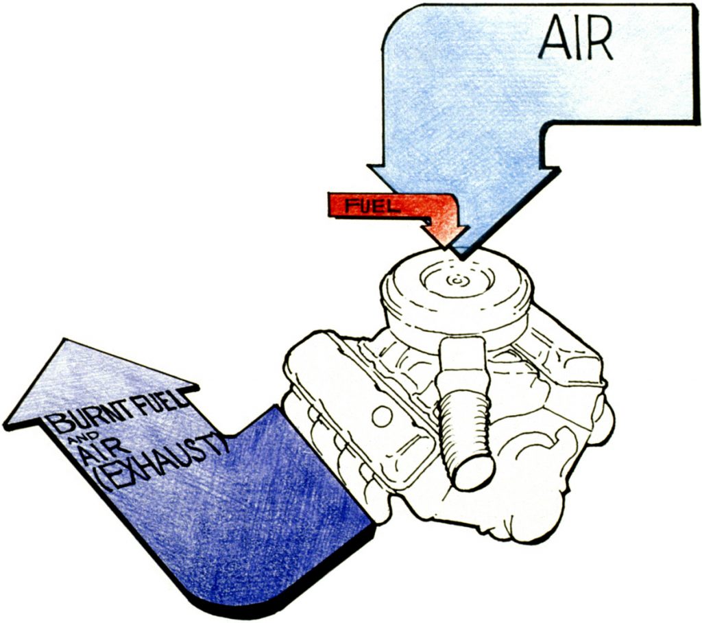
Let’s think of charge density as the amount of oxygen available to support the combustion of the fuel. The more oxygen (air) that flows into the engine, the more fuel that can be burned, and the more power the engine can make. To say it another way, assuming you mix the correct amount of fuel with the air, how much power an engine can make is dependent on airflow. For normal cruising operation, a gasoline engine operates at around a 14.7:l air-to-fuel ratio, so it would need roughly 14.7 pounds of air to mix with every pound of fuel. To make maximum power that ratio would fall to approximately 12.5:l.
Besides throttle position, many things affect airflow, such as restrictions in either the intake or exhaust paths (which can become de facto throttles in themselves), or the design of the camshaft to control valve openings and closings (see below).
Even the temperature of the incoming air will affect its density (see “Cool Air Equals Power” elsewhere on this site). But most of all, the biggest factor is the pressure of the air available to flow into the engine on its intake stroke. For a non-supercharged engine, that’s simply atmospheric pressure, or about 14.7 pounds per square inch, measured at sea level (see below).
If we use some sort of compressor to increase the pressure above atmospheric pressure, that’s called “supercharging” the engine. If that compressor is driven by a mechanical linkage to the engine, such as a belt drive or gear drive, the compressor is simply called a supercharger. However, if the compressor is driven by a turbine placed in the exhaust system of the engine, that combination of turbine and compressor is called a turbocharger (see below).
Supercharging and turbocharging are very potent ways to increase an engine’s power output. Doubling the charge density of an engine more than doubles its power output, provided an optimal air/fuel ratio is maintained. Why does the power output more than double? The answer is that the parasitic losses of the engine, such as friction and pump drives, remains relatively constant, as does relative heat loss to the surrounding air and coolant, so additional power provided by increased charge density is almost totally available to do work.
Going back to our opening description of a four-cycle engine, it should be noted that only one of the four cycles produces power. The other three cycles consume power. Anything that increases the induction pressure of an engine reduces the pumping losses for that engine on the intake stroke (see below).
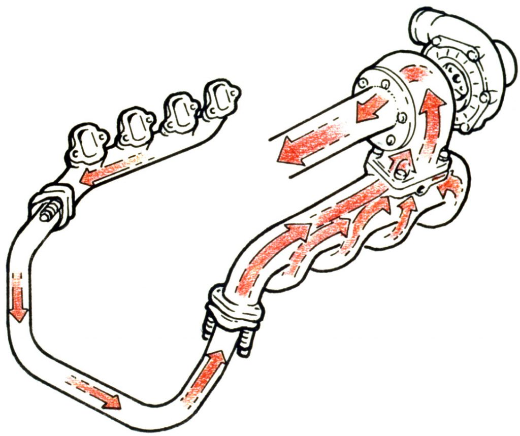
But there is no “free lunch”. It takes power to drive the compressor that creates this increased induction pressure. For a supercharger, that power comes directly off the engine’s crankshaft. In the case of a turbocharger, the turbine creates a restriction in the exhaust path, thus building exhaust backpressure between the cylinder and the turbine, increasing pumping losses on the exhaust cycle.
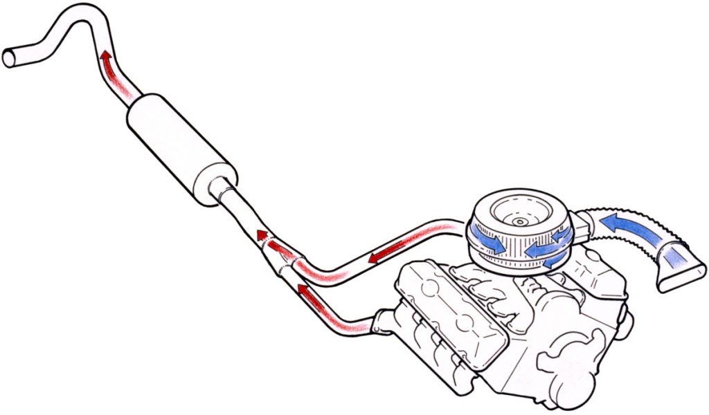
More importantly, if the exhaust backpressure rises higher than the induction pressure generated by the compressor, some exhaust gases will remain in the cylinder after the exhaust stroke to dilute and reduce the incoming air/fuel charge, and in worst-case scenarios, exhaust gases will actually flow backward into the induction system during the “overlap” period inherent in most camshaft designs where both the intake and exhaust valves are open simultaneously (see Fig.6). In this last case, such backflow is very detrimental since it raises the temperature of the incoming air/fuel charge and promotes damaging detonation.
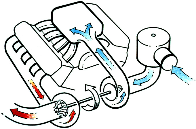
Detonation is uncontrolled combustion of the air/fuel mixture that generates excessive cylinder pressure and temperature. Detonation will quickly break, burn, or melt internal engine parts. Every fuel has detonation limits associated with pressure and temperature where the fuel self-ignites and burns uncontrollably. Thus, the maximum amount of power any spark-ignition engine can make is limited by the detonation resistance of the fuel, which is expressed as the fuel’s octane number. Consequently, being able to both control the induction pressure and the temperature of the incoming air/fuel charge is critical to building reliable supercharged (or turbocharged engines). And in the case of turbocharged engines, the turbine and compressor should be sized and matched to assure that exhaust pressure between the turbine and the cylinder, which is called “turbine inlet pressure”, doesn’t exceed the induction system pressure, which is usually called “boost” (see Fig.7). In fact, optimizing boost pressure over turbine inlet pressure is rarely discussed, yet it is one of the key elements to a successful and reliable turbocharged application, especially for racing.
A great deal of attention is often given to throttle response of turbocharged engines, which refers to the time between when the throttle is depressed and the engine responds. Frequently small, highly-responsive turbines are mated with larger compressors to quicken throttle response, but such small turbines quickly become restrictions in the exhaust system and build excessive turbine inlet pressure, creating the backflow condition commonly called “turbine choke”. Some such systems rely on today’s sophisticated detonation sensors to retard ignition timing and enrich the air/fuel mixture to suppress detonation under adverse conditions, but when these things are done, power output is greatly diminished and fuel economy suffers to the point that the engine might actually be making less power than if it was turbocharged to a lower boost level to keep it out of detonation. A properly designed turbocharger system only relies on detonation sensors as a failsafe for occasional bad fuel or a momentary overboost condition in normal operation.
As mentioned above, controlling peak induction system pressure and induction temperature is key to preventing detonation. Lets look at the temperature issue first. Whenever air is compressed, it is heated. And since heat is an undesirable that promotes detonation, cooling the compressed air is desirable, even though such cooling will lower the induction pressure. On the positive side, cooling will also increase the charge density of the incoming air. The device used to cool the induction charge is properly called a “charge air cooler”, although many people refer to it as an intercooler. Charge air coolers are heat exchangers that can utilize an air-to-air configuration, or they can be of the air-to-liquid variety. Both are effective, although the air-to-liquid variety then requires yet another liquid-to-air heat exchanger to cool the liquid. Hence, the air-to-liquid process is inherently less effective than the air-to-air concept. As a rule of thumb, every 10-degree F. reduction in charge air temperature results in a 1% increase in charge density that equates to approximately a 1% increase in power output. So charge air cooling both helps prevent detonation and increases power output.
Controlling peak induction system pressure can be done three ways. The first way is to install a pressure relief mechanism in the induction system. Such a device is often called a “pop off” or “blow off” valve that simply opens at a pre-set level. The second method is to utilize a device that bleeds off exhaust flow to the turbine. Such a device is referred to as a “wastegate” (see “How a Turbo Wastegate Works” elsewhere on this site). As with the pop-off, the wastegate would be set to open at a pre-set boost level. The third way is to properly match the turbine and compressor sizes to the application and to each other. When this is done correctly, which is called a “floating match”, inherent flow restrictions keep everything balanced.
All of the above is a simplified overview of engine science as it relates to gasoline engines. Diesel engine applications are similar in many ways, although diesels have no air throttle to vary charge density. Instead, diesels are throttled by regulating the amount of fuel injected into the cylinders at precise times. In other words, they are throttled by varying the air-to-fuel ratio. Normally this range is between 50:l (at idle) to about 22:l at full power. Going beyond 22:l produces excessive temperature, soot, smoke, and poor fuel economy. Supercharging and turbocharging do increase charge density and the total power output for diesels, just as it does for gasoline engines, and the same temperature and pressure controls apply to prevent detonation.
The basics of making power are simple. It begins with airflow, but it doesn’t end there. That’s just the beginning. Then fuel must be properly metered to match the airflow. And finally, precise controls need to be put in place to optimize related systems, such as ignition (for gasoline engines), turbocharger boost, etc. When done correctly as a system, not only is power increased, drivability, reliability, and economies are also enhanced. Done incorrectly, the results can be destructive to the engine, pushing it beyond the factory-specified safe operating limits. At Banks Power, we’re experts at doing it correctly.
Whatever power enhancement products you consider, use the engine science presented here to evaluate how those products affect the basics of engine operation and how they achieve their gains. Then you’ll be in a better position to make an informed purchase decision.