Fuel System and Plumbing for Jay Leno’s Tank Car
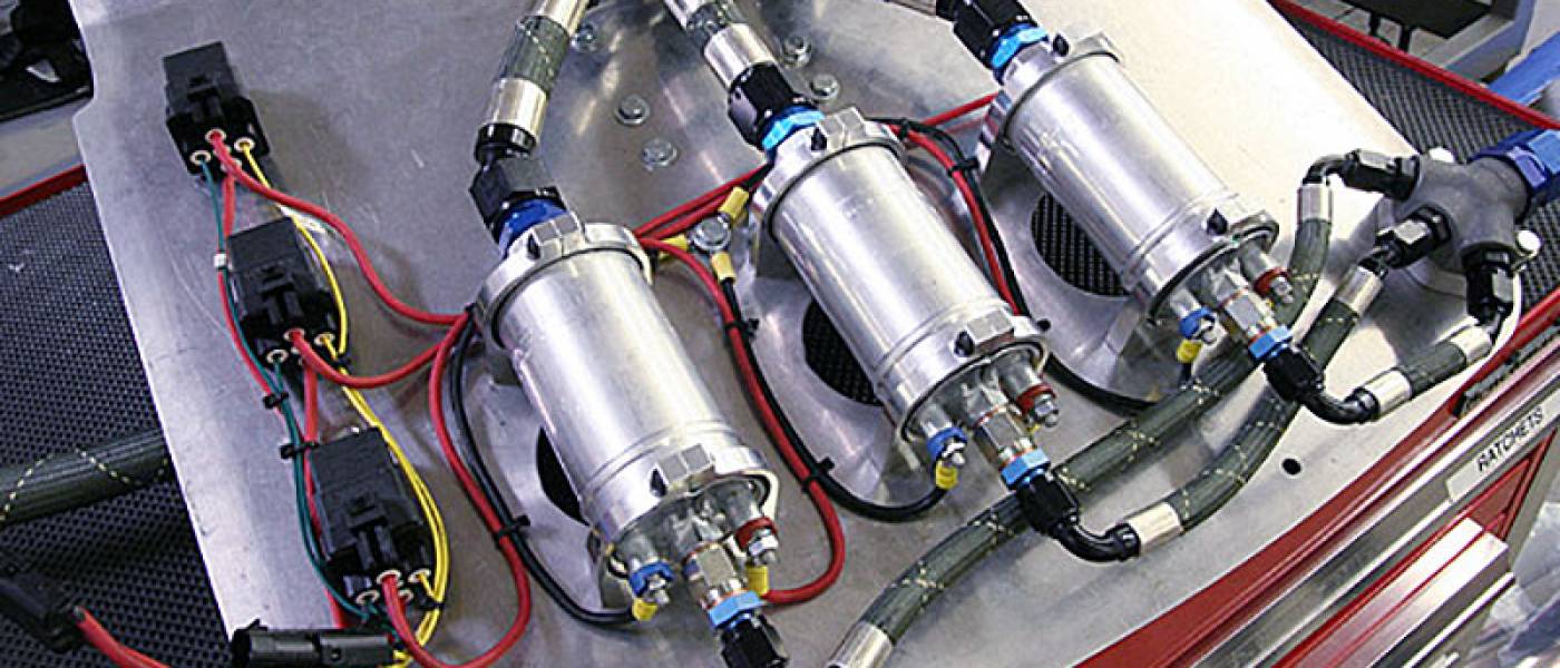
Three pumps, no waiting! On the wet side of the EFI system, Bosch provided us with their 200 liter-per-hour, 5-bar (72 psig) electric fuel pumps. With each pump putting out just under one gallon per minute, it’ll take three of them in parallel to feed this monster. We mounted the pumps and relays on one side of a vertical panel with twin inlet filters on the other. All of the hose assemblies were made using XRP’s HS-79 smooth-bore Teflon/Kevlar hose and crimp-on hose ends.
Keep your shades on when you look at this thing! And it’s not done yet, the shuttle valve outlet horns are not finished, and we still have throttle linkage and other things to hook up. Now we’ve got to switch over to the exhaust side and start cutting and fitting big stainless tubing to get those turbos spinning. See you next time!
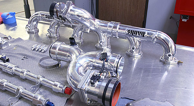
And now for the fun part! We can start to install some of the “bling” onto the engine and see what all this “eye candy” really looks like. Before it could go on, all pieces were cleaned, and any sensors and fittings were pre-assembled to make installation easier. As with the exhaust manifolds, we had new intake gaskets stamped so our manifolds would have a good seal at the ports.
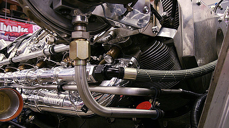
Turbocharger oil returns to the oil pan through this 5/8-inch stainless tube connected to the turbocharger support bracket. Each rocker box on the AV 1790 engine has an external oil drain tube which is paired with an adjacent cylinder. We fabricated special fittings to tie the turbo oil drains into the rear rocker box drains where they enter the crankcase.
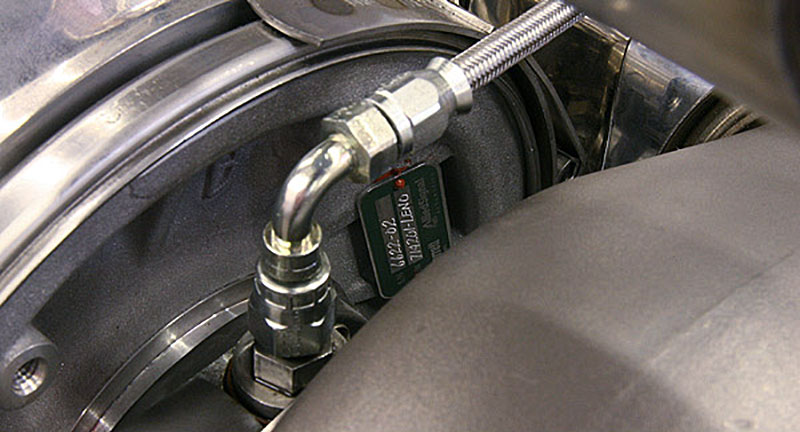
While we were routing hose, we made up the oil feed system to the turbocharger bearings. These Honneywell/Garrett ball-bearing turbos don’t require much oil volume, so a single -3 line supplies each turbo. The AV 1790 V12 engines had an oil pressure driven speed governor linked to the throttles. Of coarse Jay had already ditched the governor, so its oil supply fitting was used as a source for turbo lube.
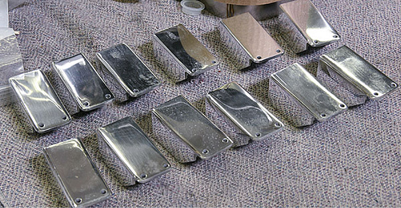
To make it less obvious that the engine has been “modernized”, these machined aluminum covers were made to go over the injectors. All of the injector and sensor wiring has been hidden as much as possible to retain the “50’s look of the components. Fittings and hose ends were gold zinc or black anodized to go with the original military/industrial look of the hardware. Although there are a few red/blue anodized fittings on the car, these are hidden when the bodywork is in place.
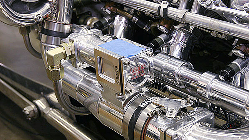
A high-capacity fuel pressure regulator bypasses fuel from the front of the fuel rails to maintain a 50 psig base pressure at the injectors. The regulator’s diaphragm is referenced to intake manifold pressure so the fuel pressure will rise with boost pressure. Bosch fuel pressure and temperature sensors installed in the regulator body signal the EFI controller to adjust fuel delivery.
Prototype fabricator Jim Jensen slides the completed fuel pump panel into place between the massive differential housing and the tail-end bodywork. The fuel tank is just above with two -12 lines feeding the twin filters. A single -12 line runs forward and divides into the fuel rail inlets, while a -8 line sends return fuel from the regulator back to the tank.

