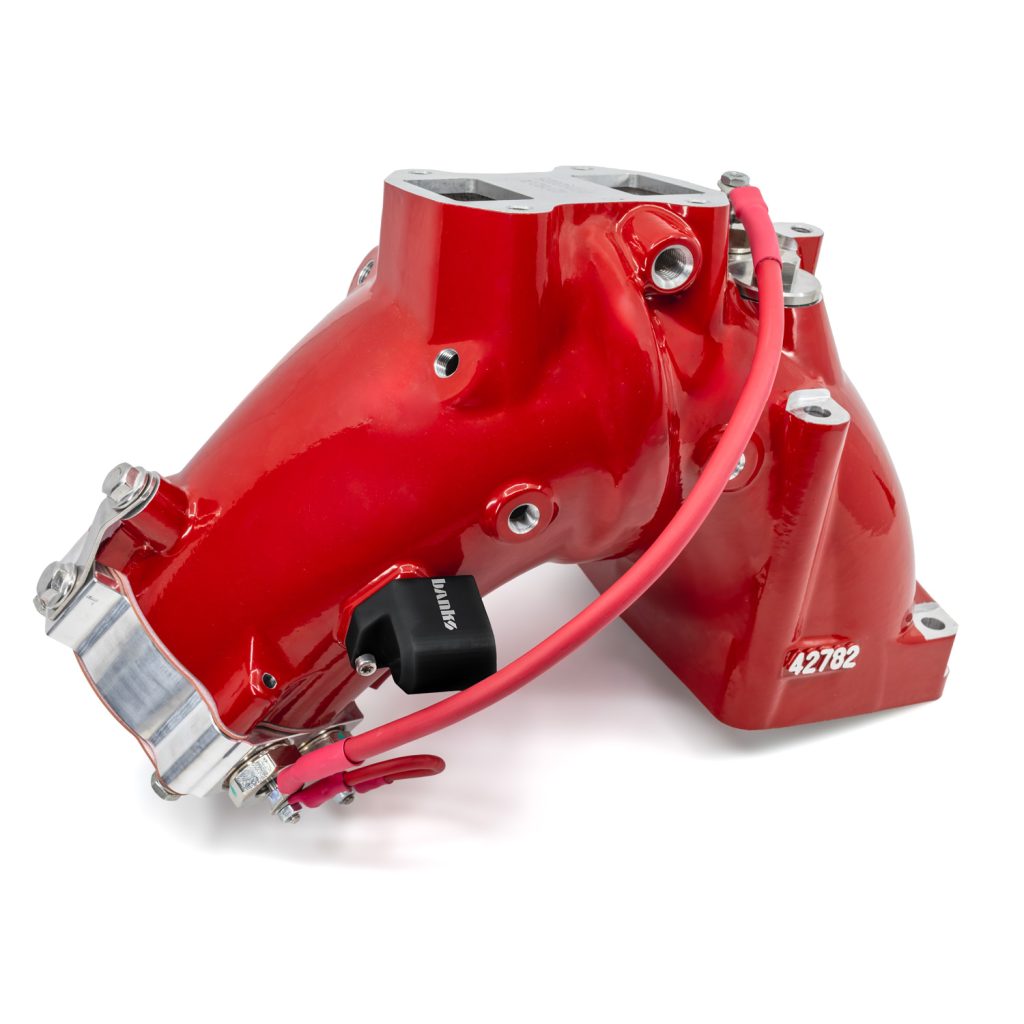
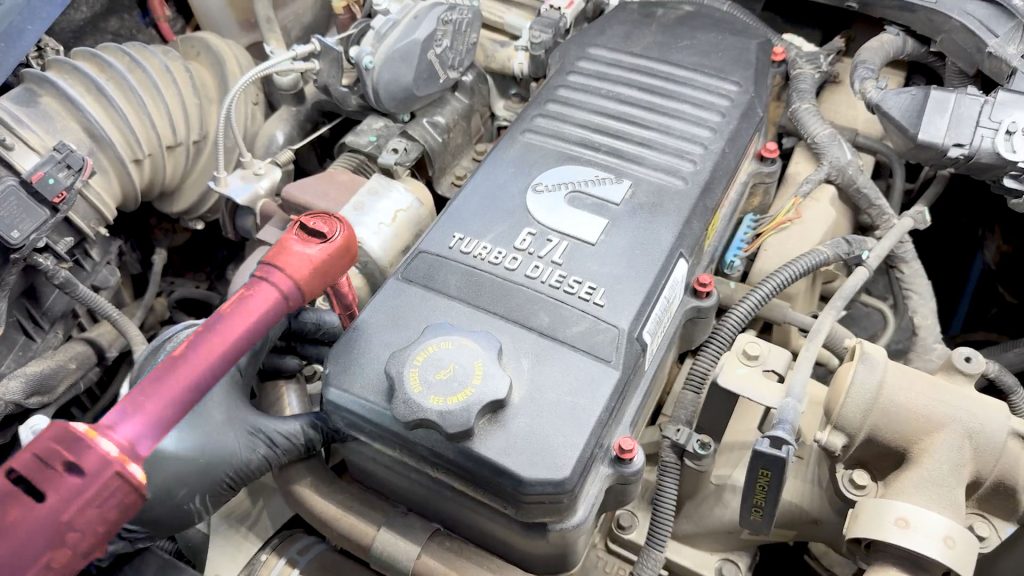
97705 Dual Heat Monster-Ram Intake System w/fuel line 2013-18 RAM 6.7L
INSTALL INSTRUCTIONS
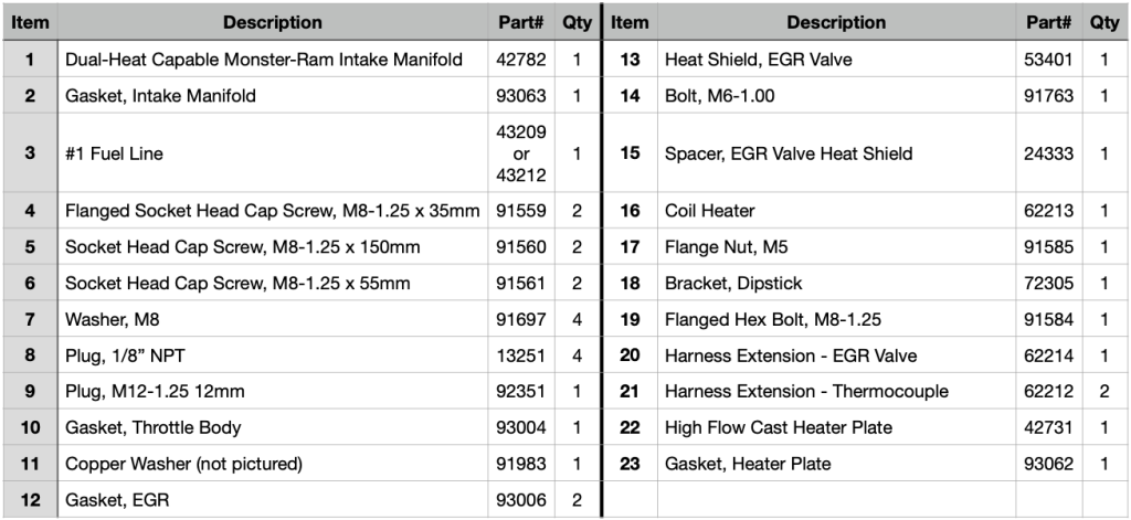
Part #s
42798, 42798-PC, 42798-B
Monster-Ram® Air Intake 2013-2018 RAM 2500/3500 6.7L Cummins
Please read through the following instructions thoroughly before starting your installation. If you have any questions please visit our Support Page.

Dual Heat Capable Monster-Ram w/Intake Plate Install Video

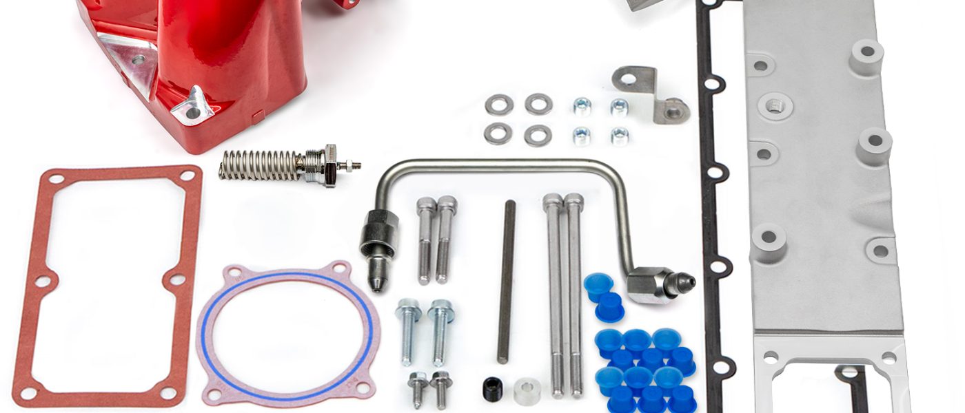
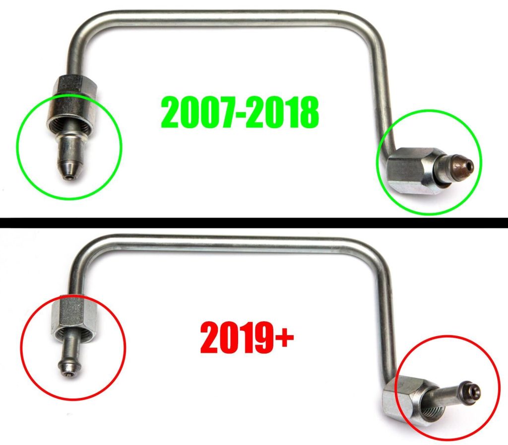
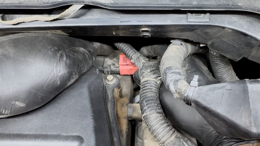
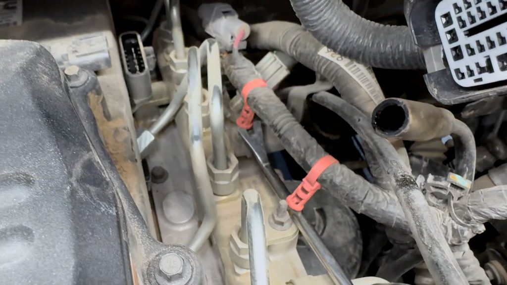
In effort to make sure you have the right kit for your model year. Visually check which fuel line is included in your kit before starting installation.
Important Notes:
IMPORTANT!
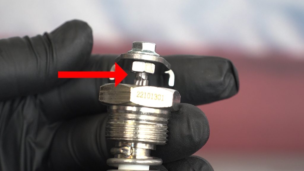
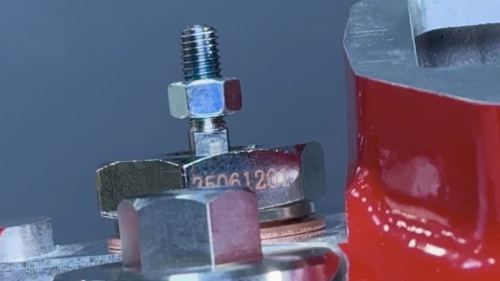
Coil heater preparation: The lower nut must remain 1/8″ above the coil heater body (about 2 threads visible).
Take care when installing OEM heater wire ring terminal, it must be sandwiched between the upper and lower nut. If the lower nut is too low, the ring terminal could contact the body of the coil and will short out.
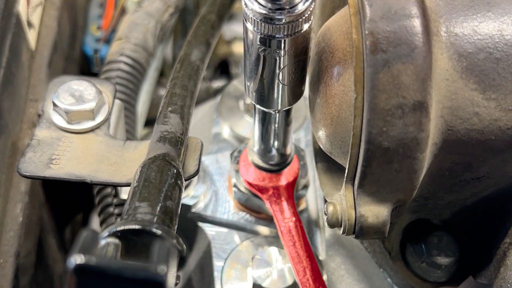
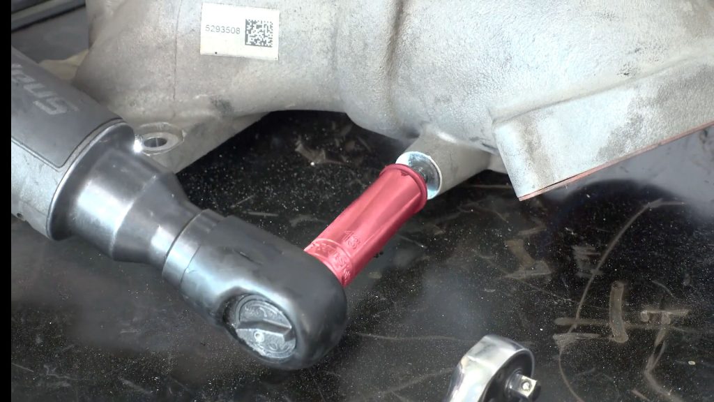
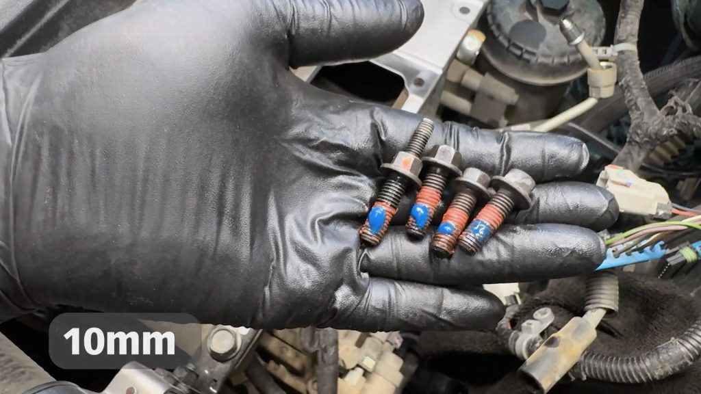
When tightening the nut, it is very important to use a 10mm wrench or socket on the top nut and an 8mm open-end wrench on the bottom nut to prevent the threaded post from rotating. If the threaded post rotates, it can break the ceramic insulation it’s surrounded by.
If the OEM heater wire touches other metal components, an open short will occur.
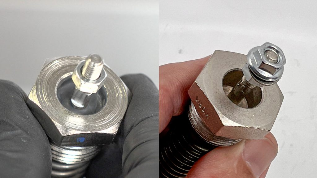
Coil-Heater Variants
Your kit may include one of two different style heater coils. One with a visible ceramic insulator, or one that isn’t visible. Both offer the same level of heating performance.
Copper washer: All kits now ship with a copper crush washer. Place this washer between the coil heater before screwing it into the Monster-Ram.
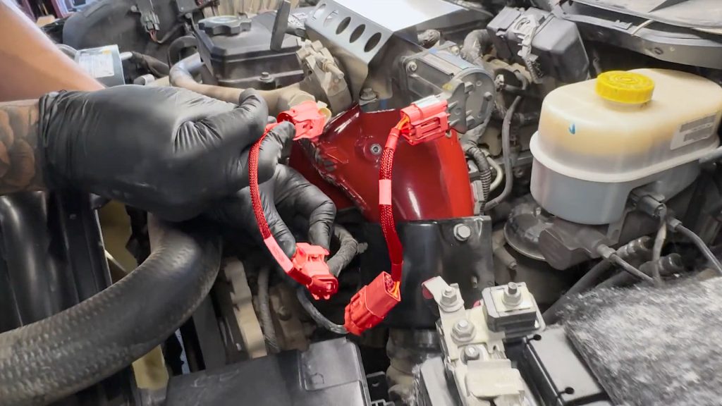
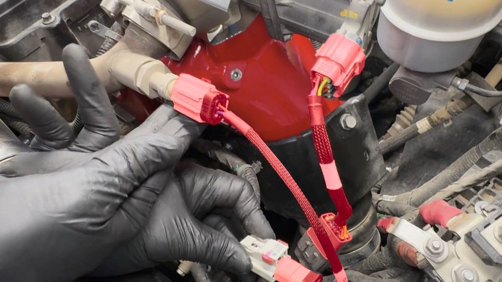
Installing a Dual Heater Upgrade?
See our Dual Heater and Billet Heater Upgrade supplement for important wiring information and diagrams.
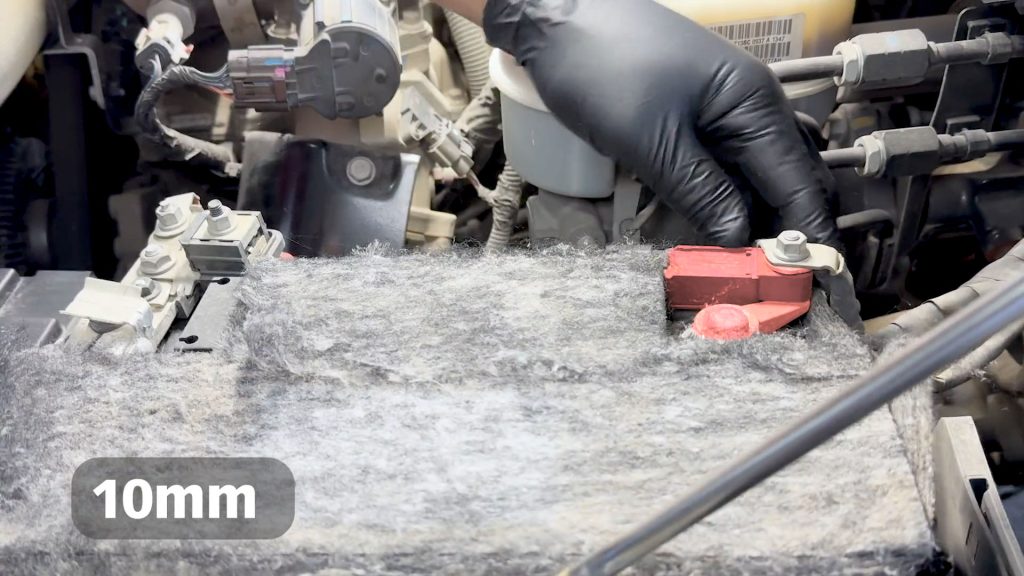
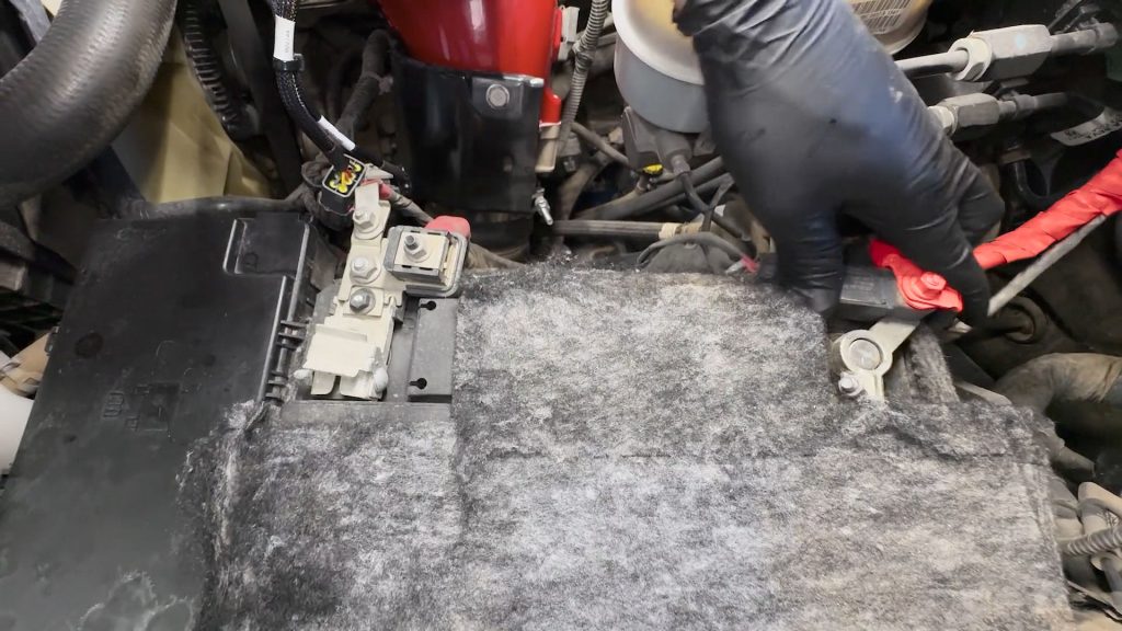
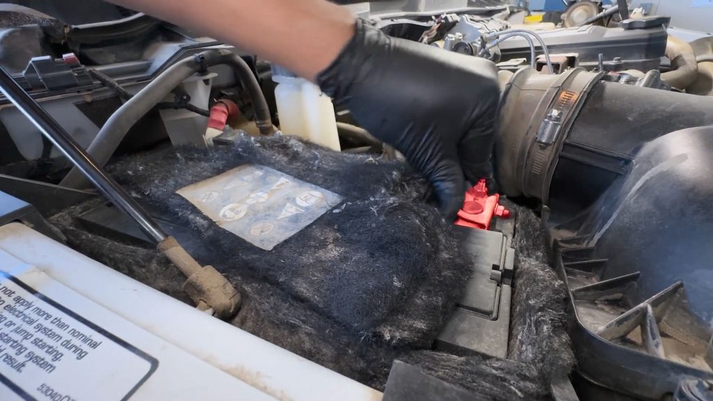
1. Disconnect Batteries
1. Use a 10mm socket to loosen the nut. Place a rag around each of the negative battery cable ends; this will prevent them from touching the battery again and arcing during the install as you work.
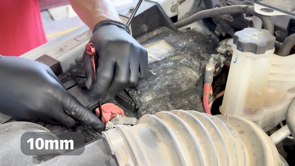
2. There is one on each side of the engine bay.
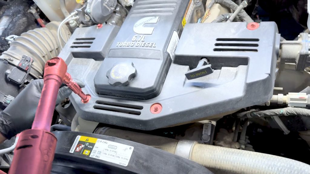
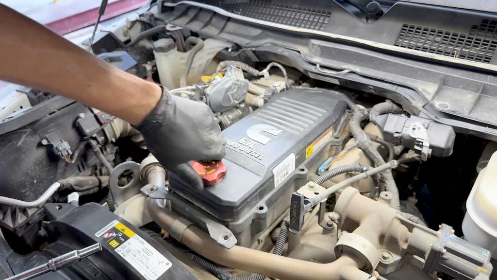
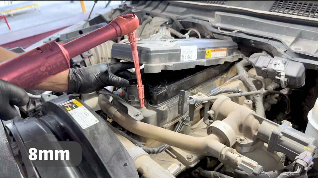
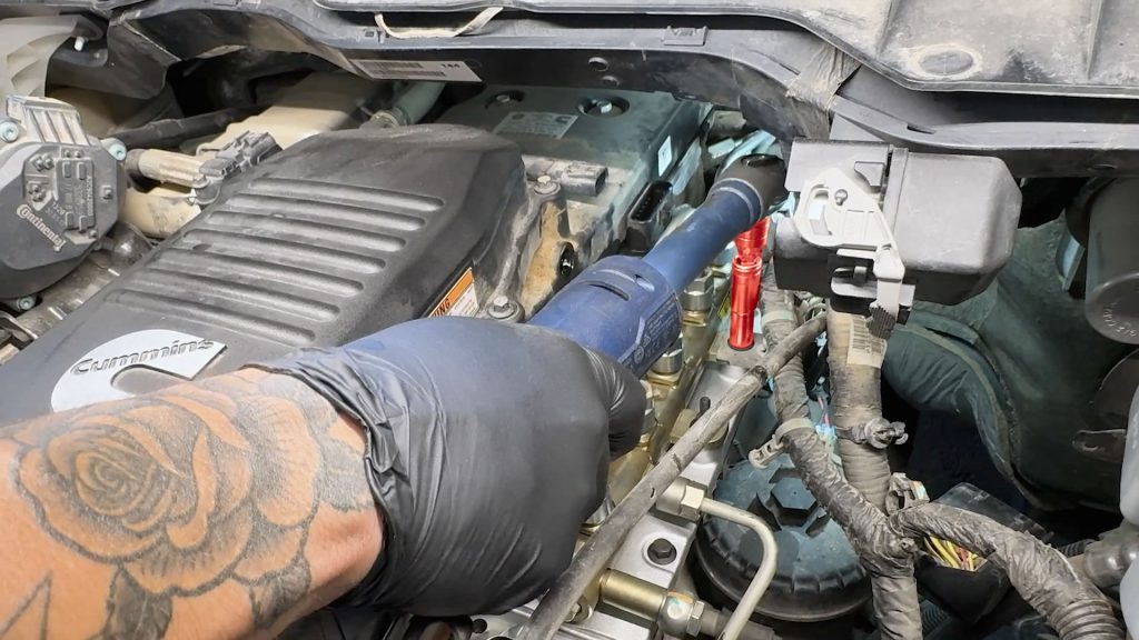
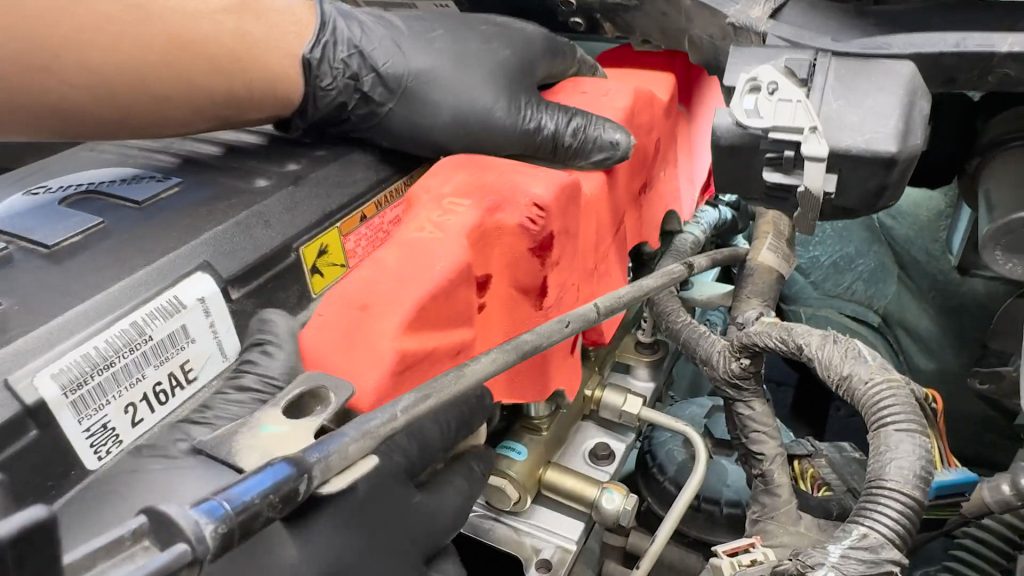
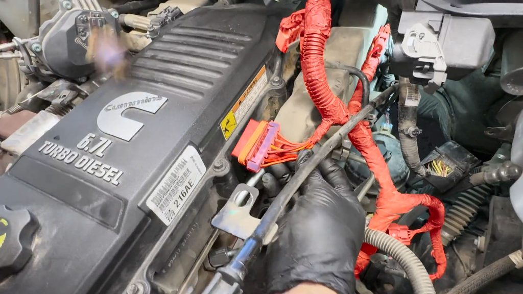
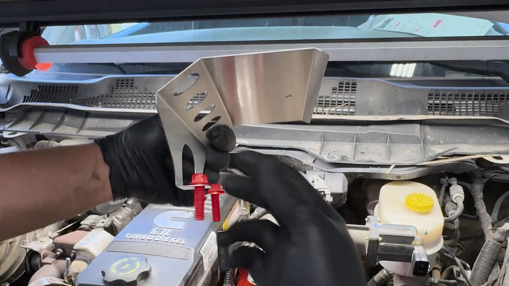
2. Remove Engine Cover
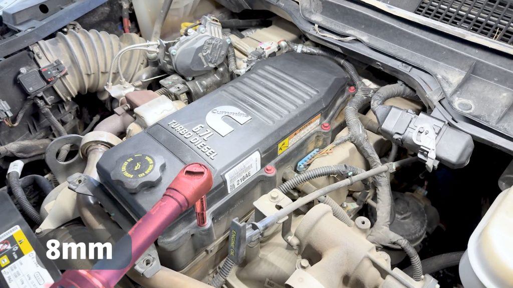
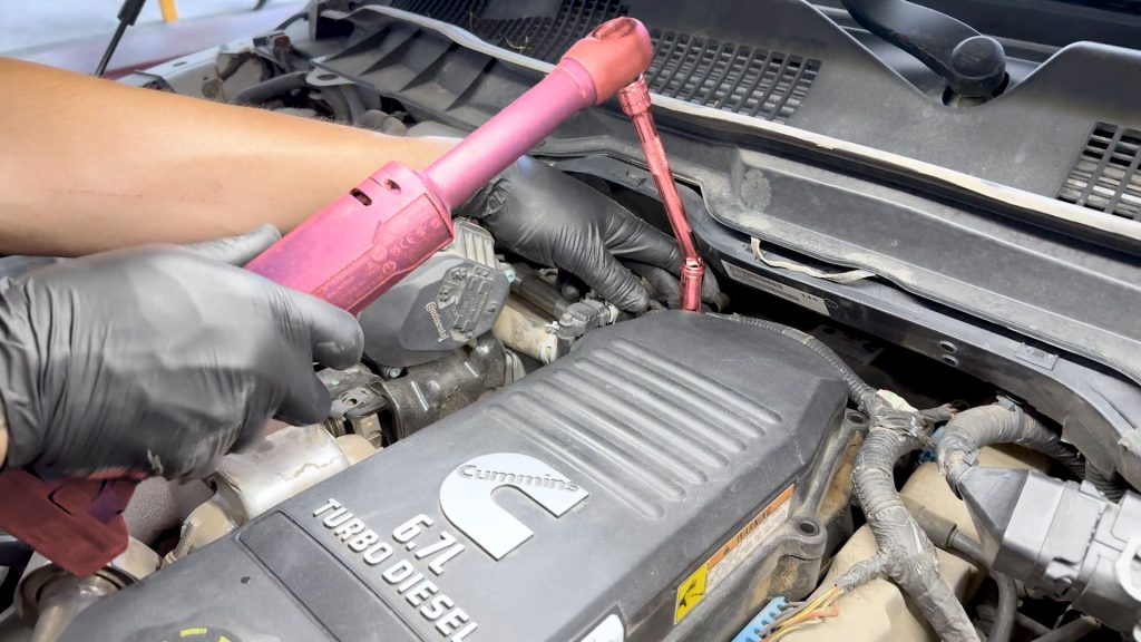
1. Use an 8mm deep socket to remove the four bolts holding the cover down.
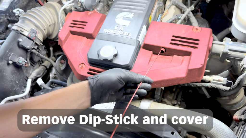
2. The dipstick needs to be removed for the cover to come off.
3. Don’t forget to replace it after the removal of the engine cover.
3. Valve Cover And Engine Harness
1. With an 8mm socket, remove the 8 bolts that secure the valve cover to the cylinder head.
Using a wobble socket is helpful for the rear two.
2. Free the engine wire harness from the valve cover while you continue to remove the remaining bolts.
3. Remove the oil cap.
4. With an 8mm socket, remove the two bolts that hold down the support bracket for the engine cover.
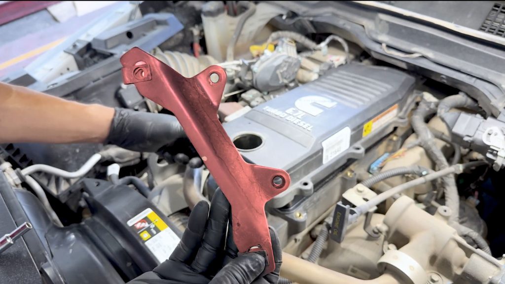
It will not be reused.
5. Reinstall the bolts into the valve cover.
The two with the studs go on the rear passenger side.
4. EGR Crossover Tube Removal
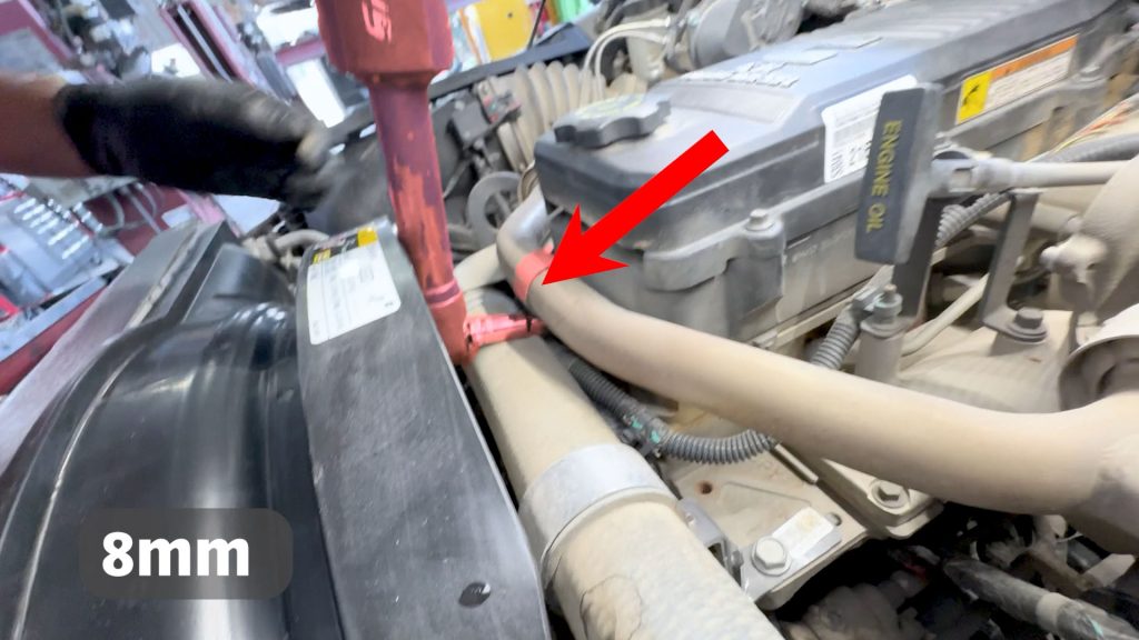
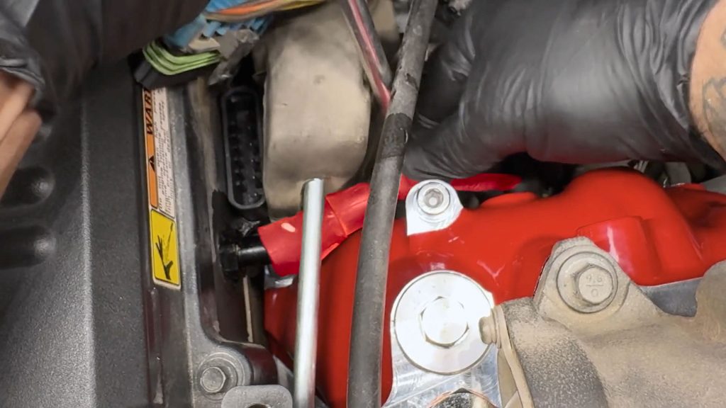
1. With an 8mm socket, remove the bolt that holds the P clamp on the EGR crossover tube..
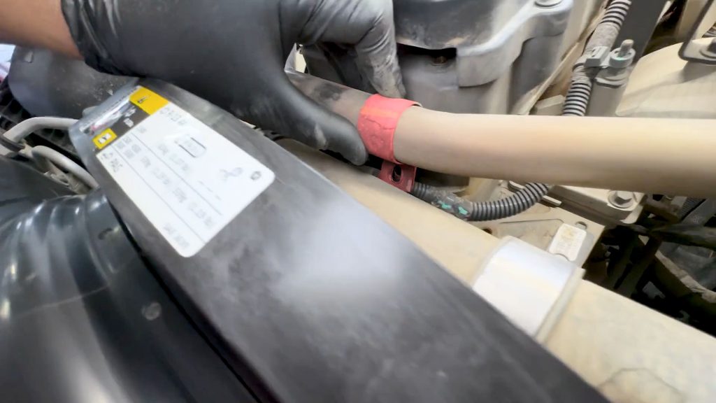
The P clamp will not be reused.
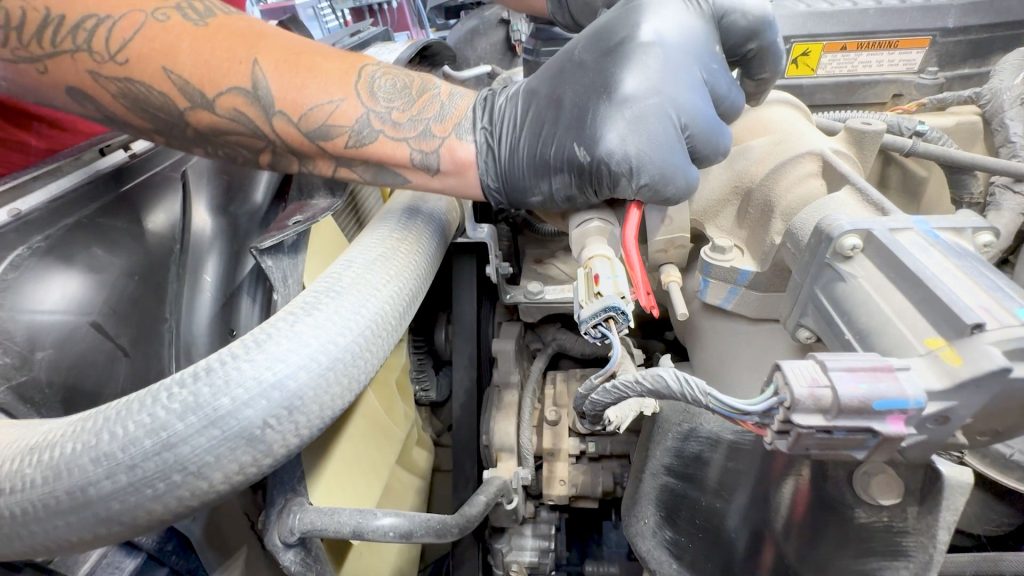
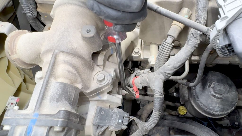
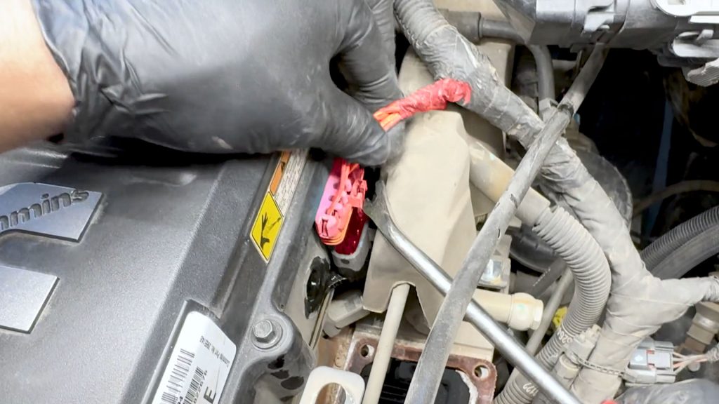
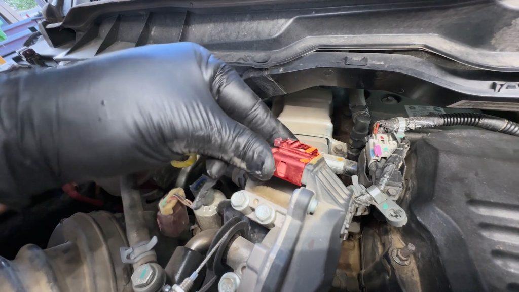
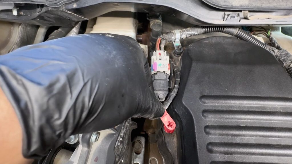
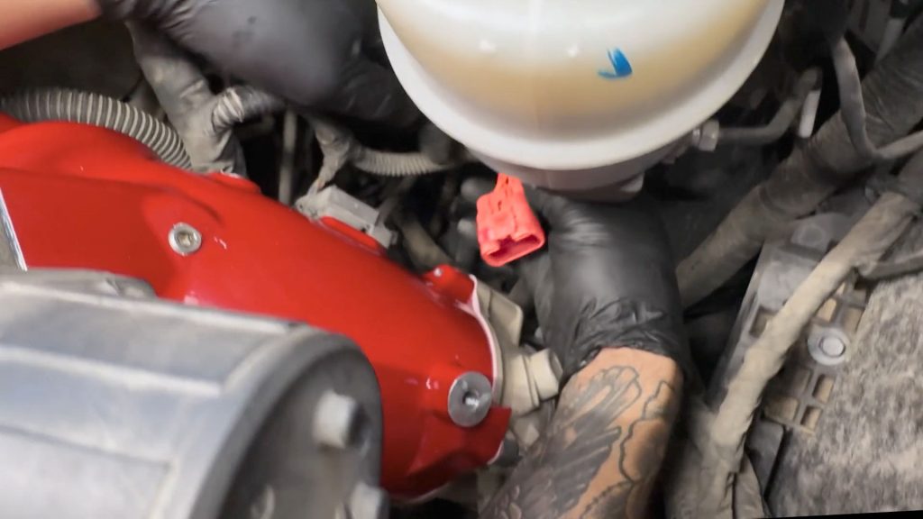
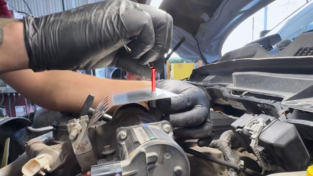
2. With a flat-blade screwdriver, slide the red locking tab on the EGR temp sensor to unlock it.
3. Unplug the EGR temp sensor.

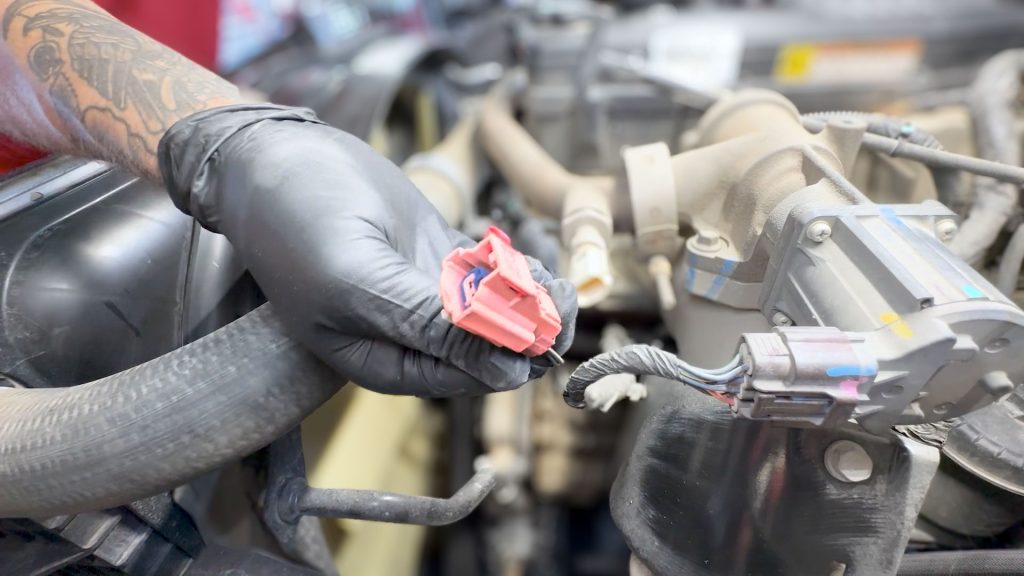
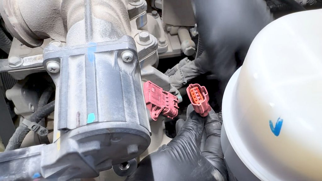
4. Unplug the EGR Valve.
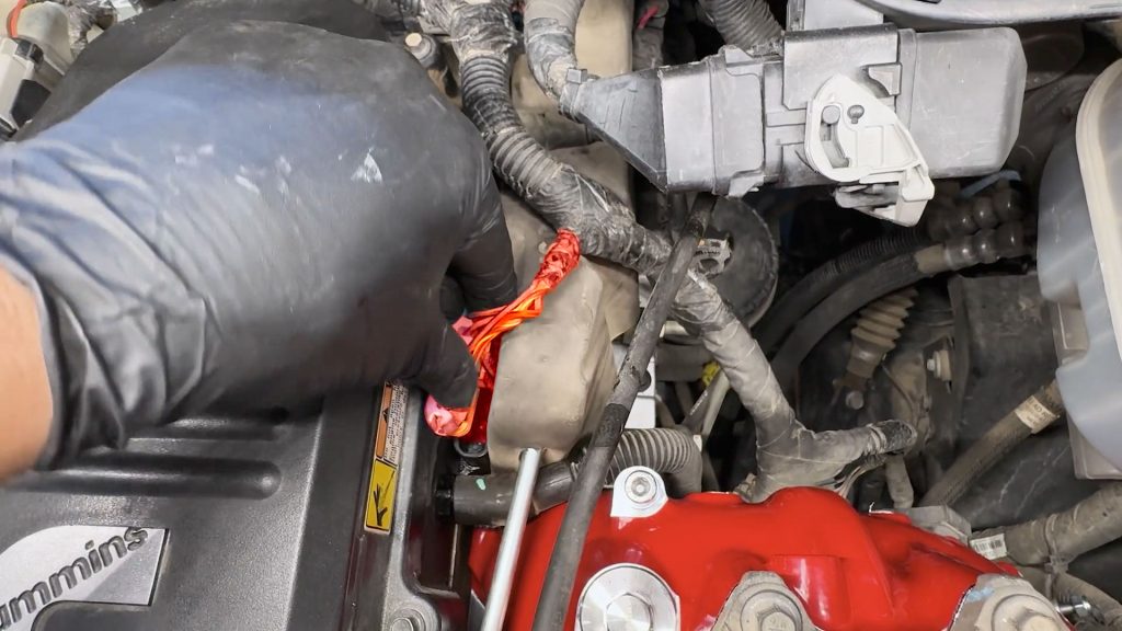
5. With a flat blade screwdriver, free the engine harness from the throttle valve heat shield.
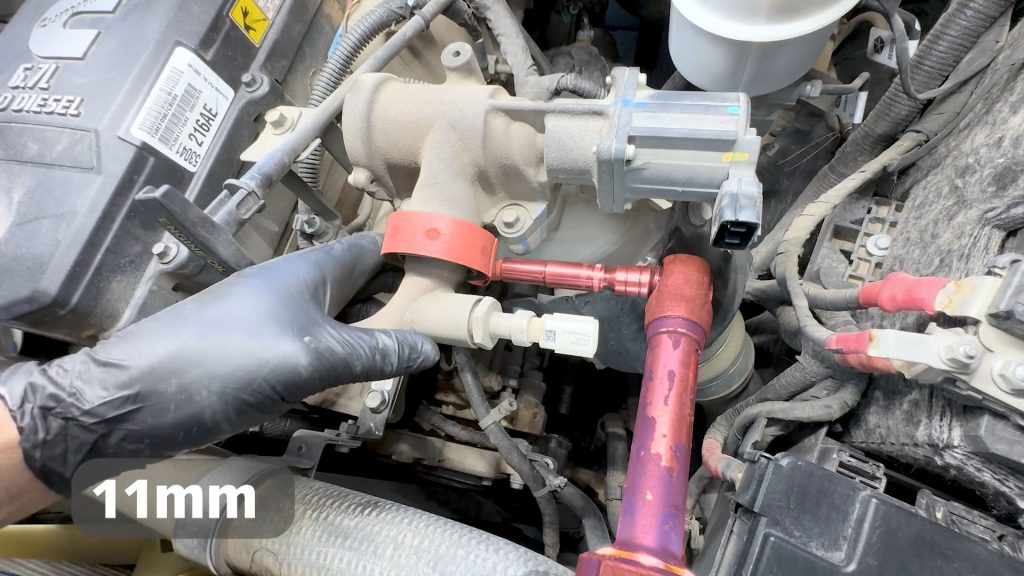
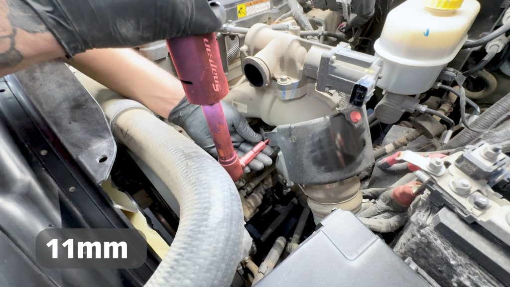
6. With an 11mm socket, loosen the V-band clamp on the driver side.

7. With an 11mm socket, loosen the V-band clamp on the passenger side.
8. Rotate the passenger side clamp so that its facing up.
9. With your hand under the passenger side V-Band, carefully pull away and catch the gasket that is between the tube and EGR cooler.
10. The passenger side gasket is flat.
11. The driver’s side gasket is conical.
5. Engine Harness.
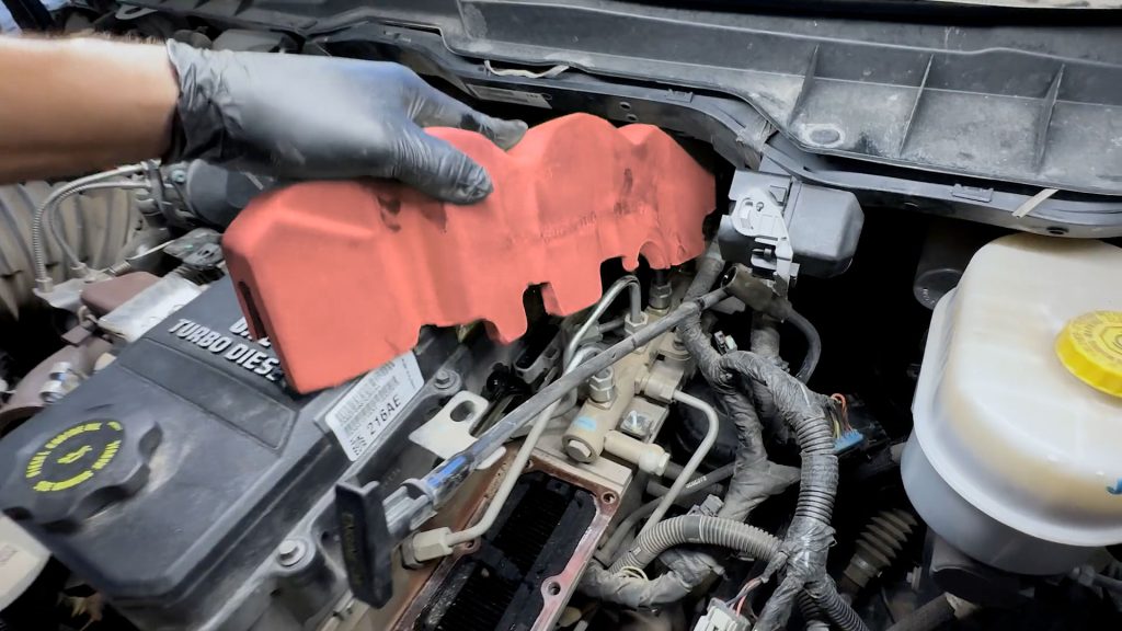
1. With an 11mm socket, remove the two bolts that hold the throttle valve heat shield.
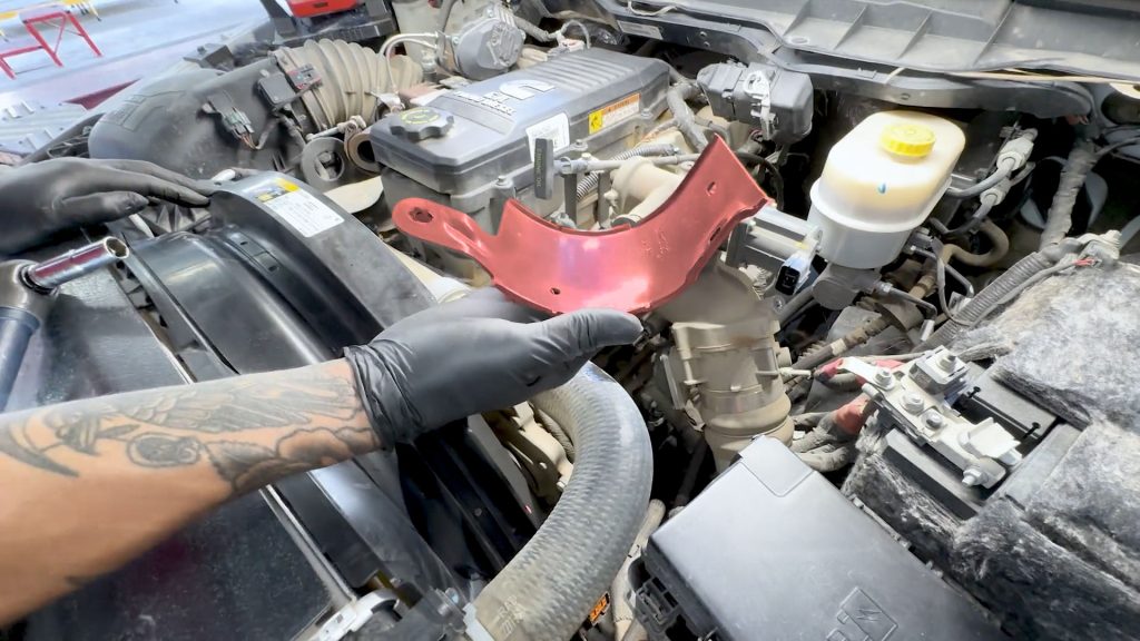
Set it aside for now.
2. Cut the cable tie that is on the dipstick tube.
3. Using a flat-blade screwdriver, free the harness from the stud on the dipstick tube bracket.
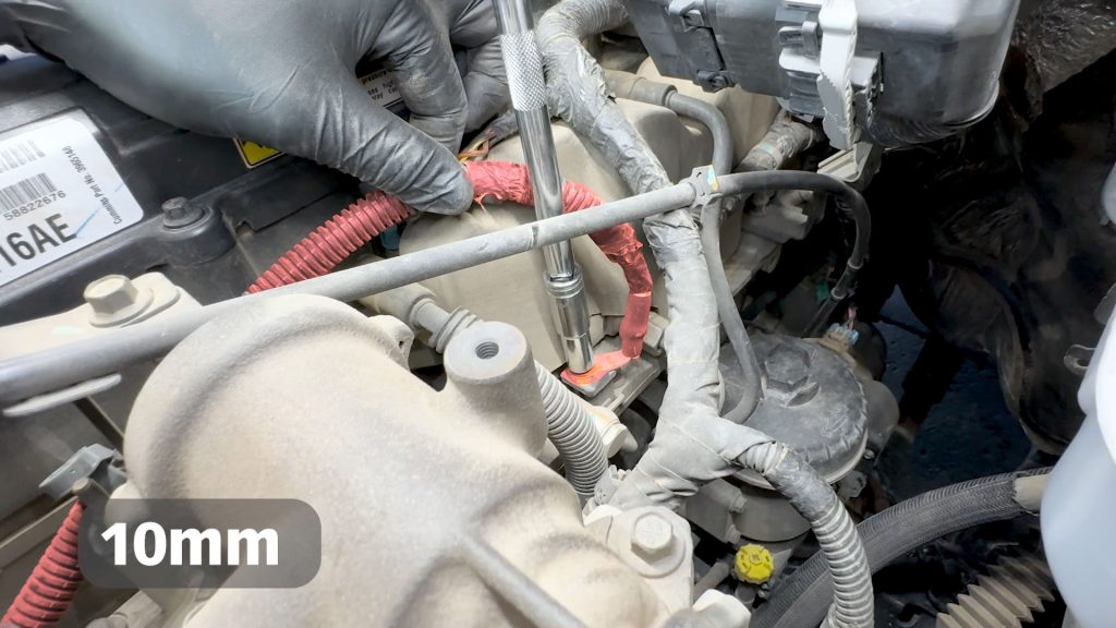
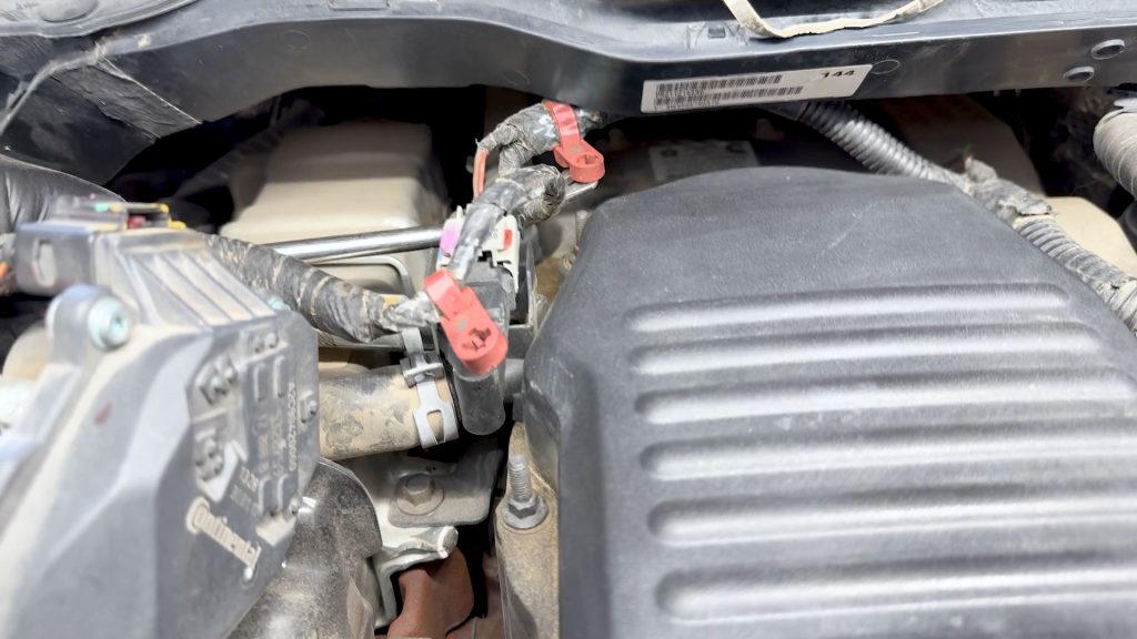
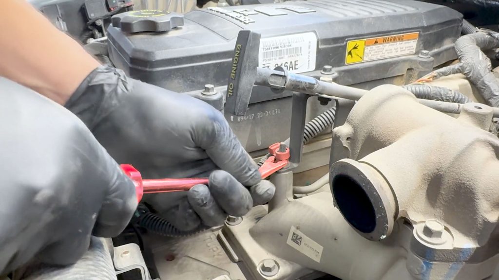
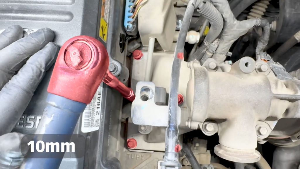
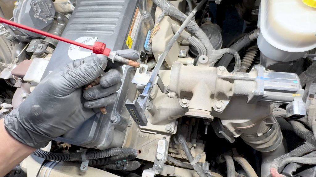
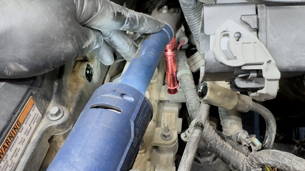
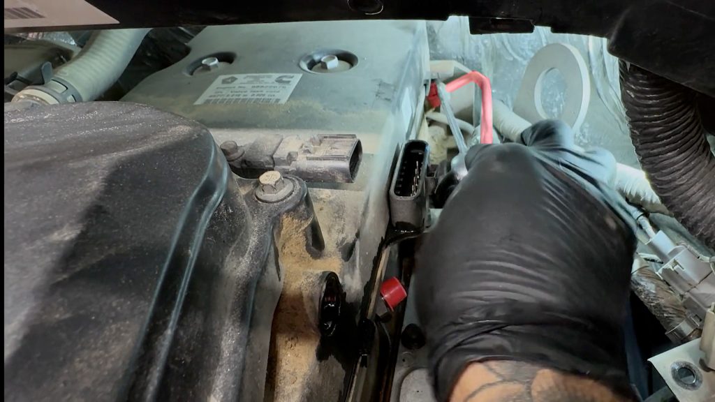
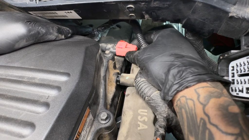
4. With a 10mm socket, remove the nut that holds the 12V power lead to the grid heater post.
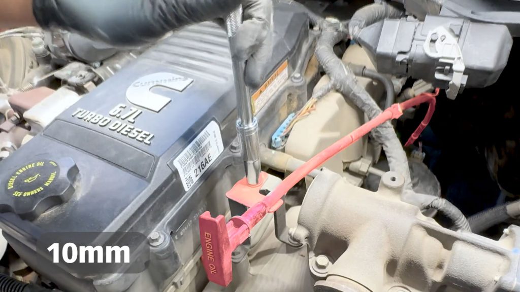
5. Remove the top nut that holds the dip stick tube to its bracket.

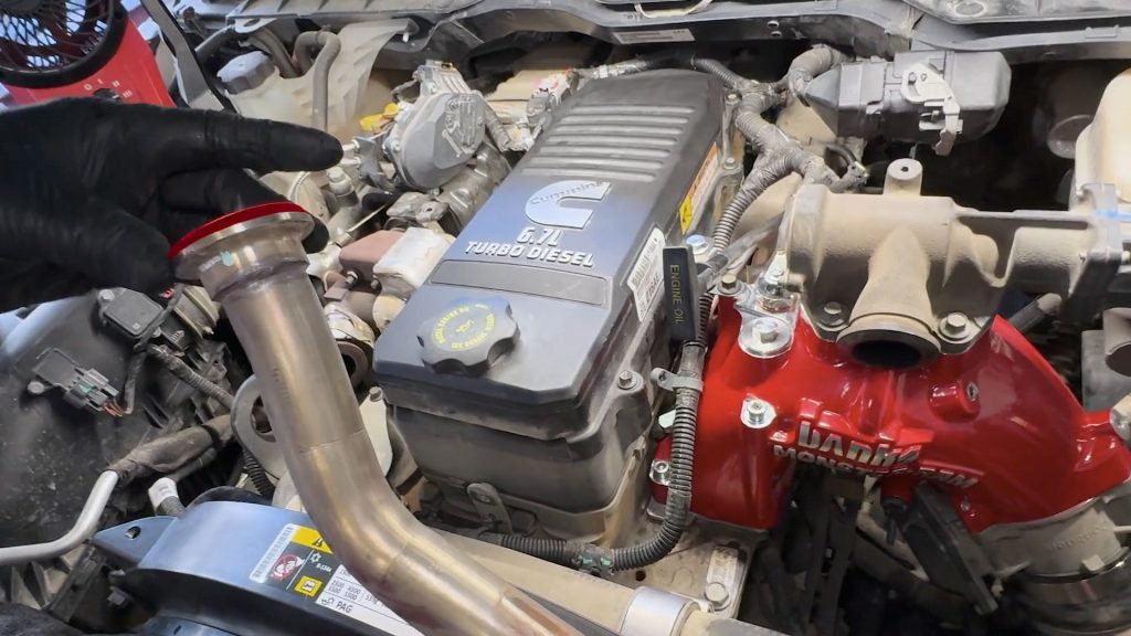
6. Bend the dip stick tube up a few inches; this will allow for extra room for the Monster-Ram.
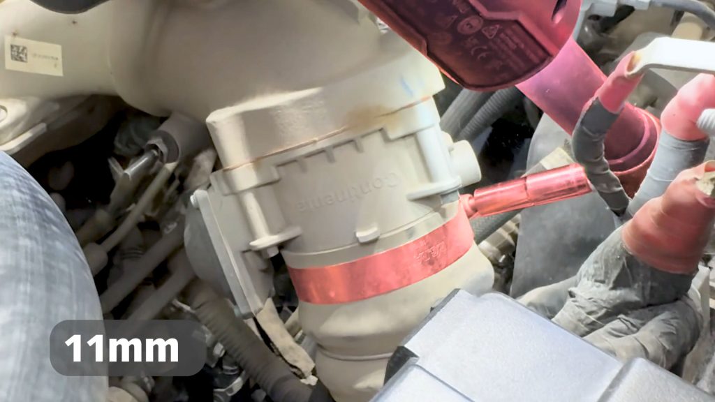
7. With an 11mm socket, loosen the clamp that holds the boost tube to the throttle.
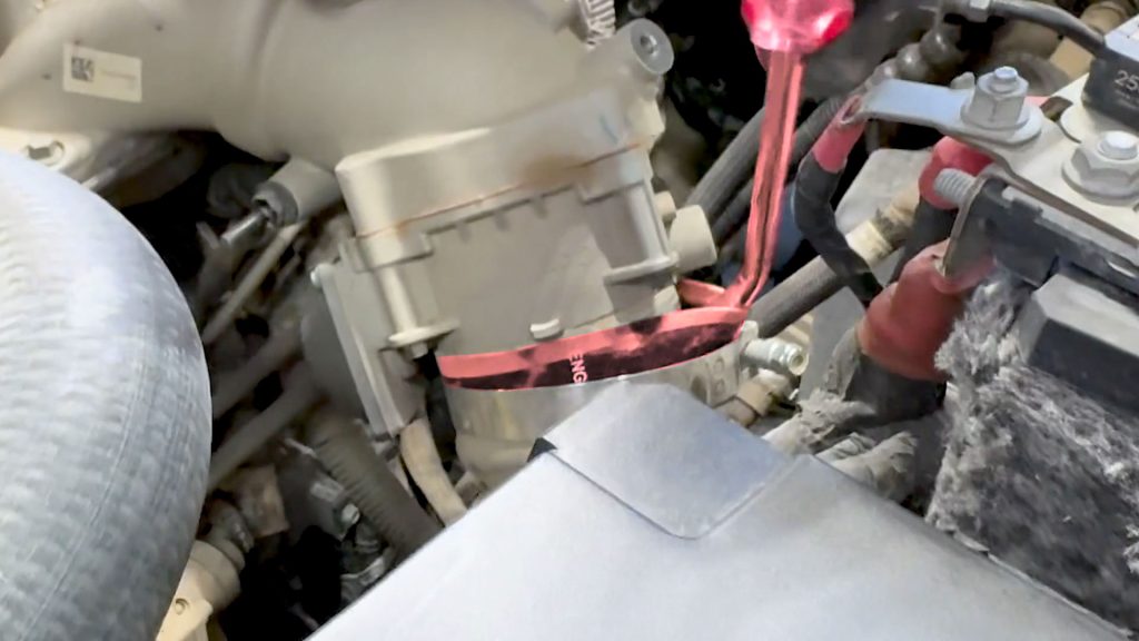
8. With a flat-blade screwdriver, break the boost tube’s grip from the throttle body. This will help in the removal of the intake elbow later.
9. On the backside of the intake elbow, free the engine harness from the stud with a flat blade screwdriver.
10. Unplug the MAP sensor on the back side of the intake elbow.

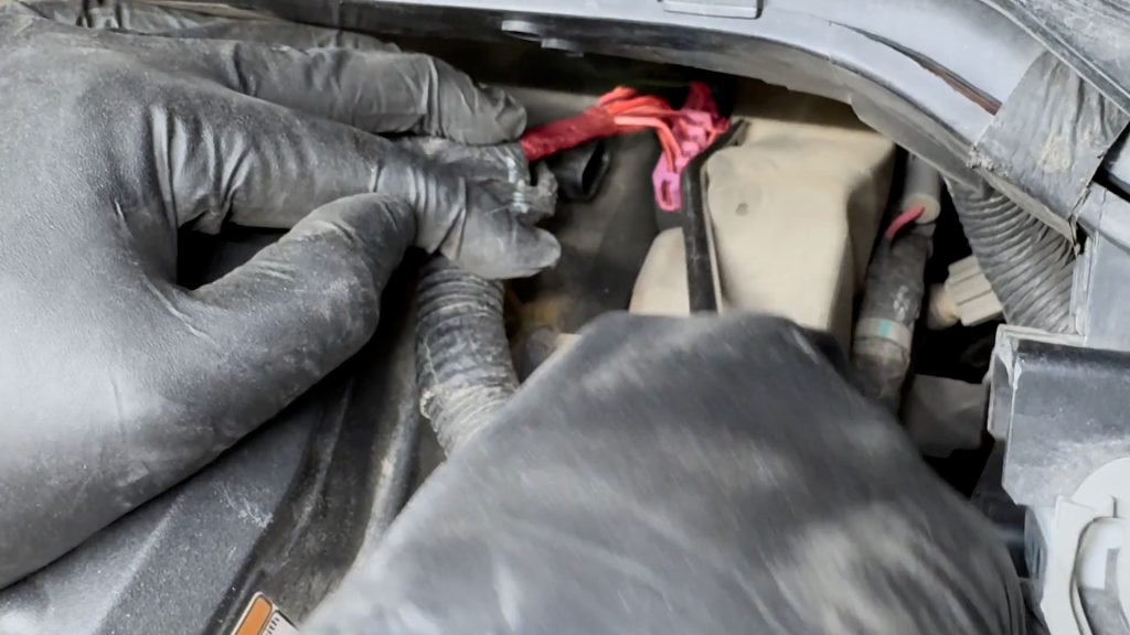
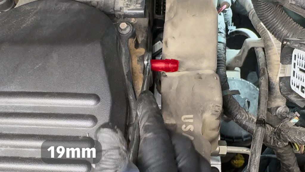
11. With a flat-blade screwdriver, free the PCV hose from the cylinder head.
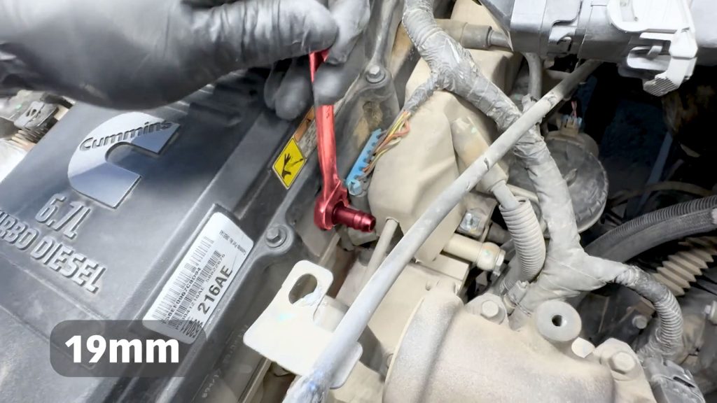
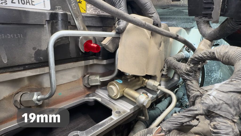
12. With a 19mm wrench, remove the barb from the cylinder head.
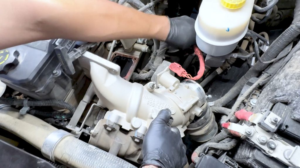
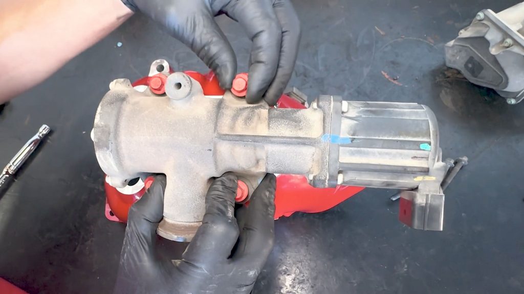
6. Intake Elbow Removal
1. With a 10mm deep socket and extension, remove the 6 bolt that holds the intake elbow.
Use a telescoping magnet tool to reach the hard-to-get bolts.
2. Rotate the intake horn on its side to free it from the boost tube, and locate the throttle valve plug on the back side.
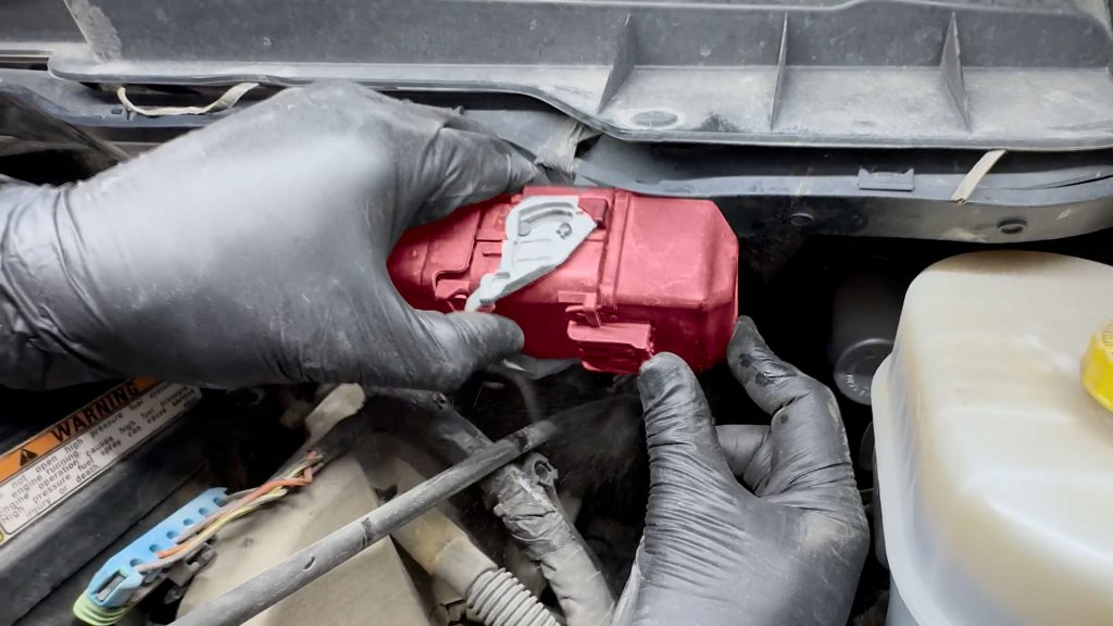
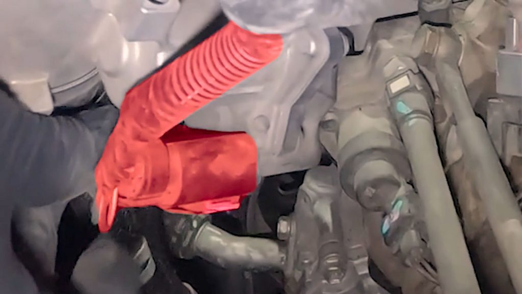
3. Slide the red locking tab to unlock and unplug the throttle valve.
4. Lift the factory intake elbow up and out of the truck, and move it to a workbench.
5. Place a rag over the factory boost tube. Place the clamp back over to hold the rag.
7. Engine Harness Removal
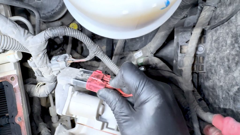
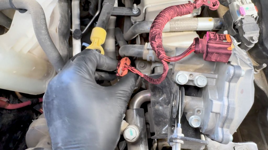
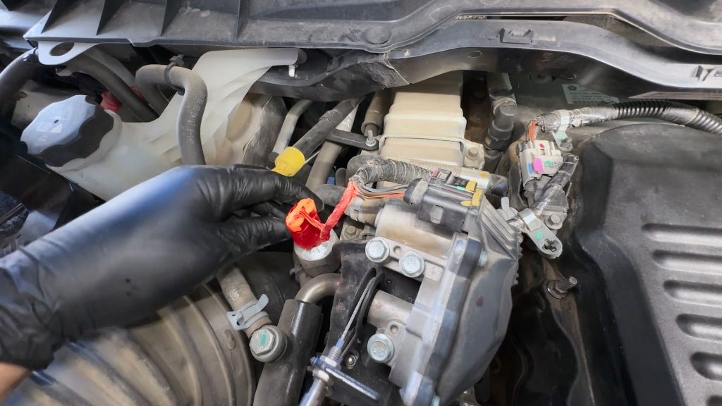
1. Unplug the harness from the passenger side EGR valve and cooler.
2. Slide the pink locking tabs back to free the plugs.
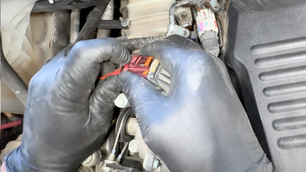
3. Follow the engine harness around the back side of the valve cover. Slide the pink lock to unlock the sensor and unplug it.
4. Continue around to the driver’s side. Slide the pink lock, and unplug the sensor.
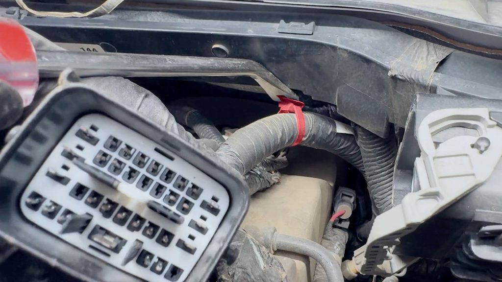
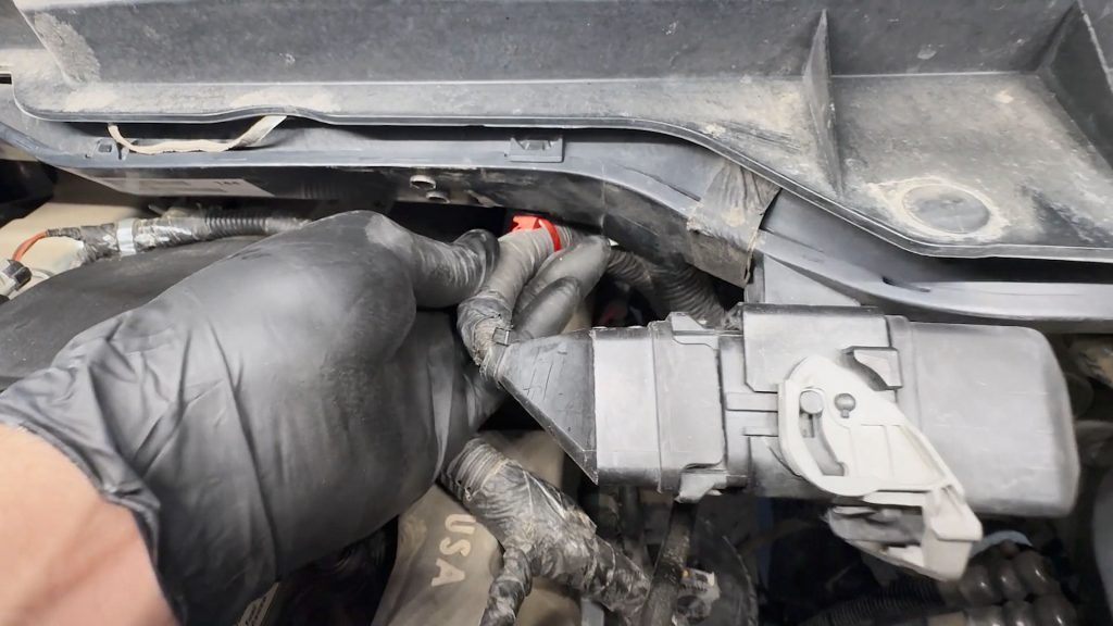
5. With a flat-blade screwdriver, depress the center of the plug to unlock and unplug the large blue/green plug.
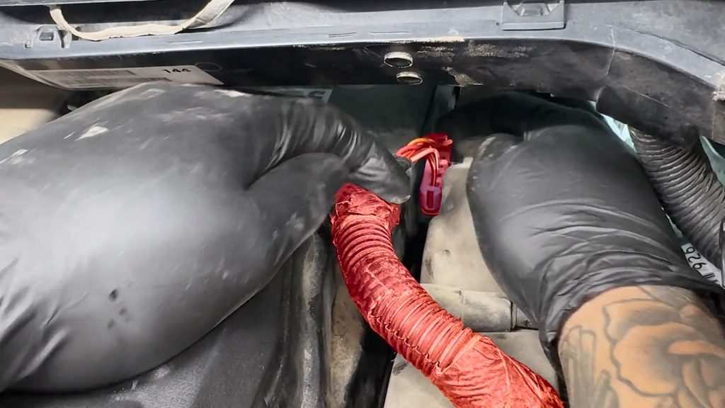
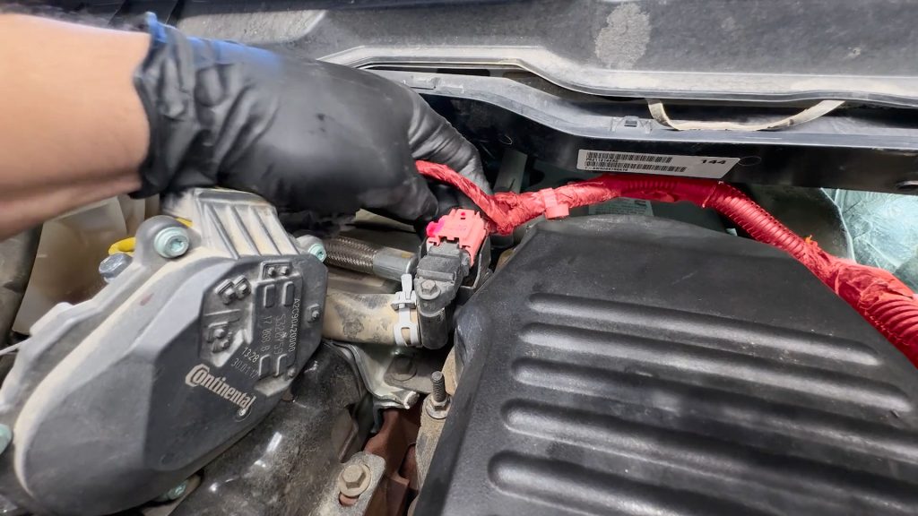
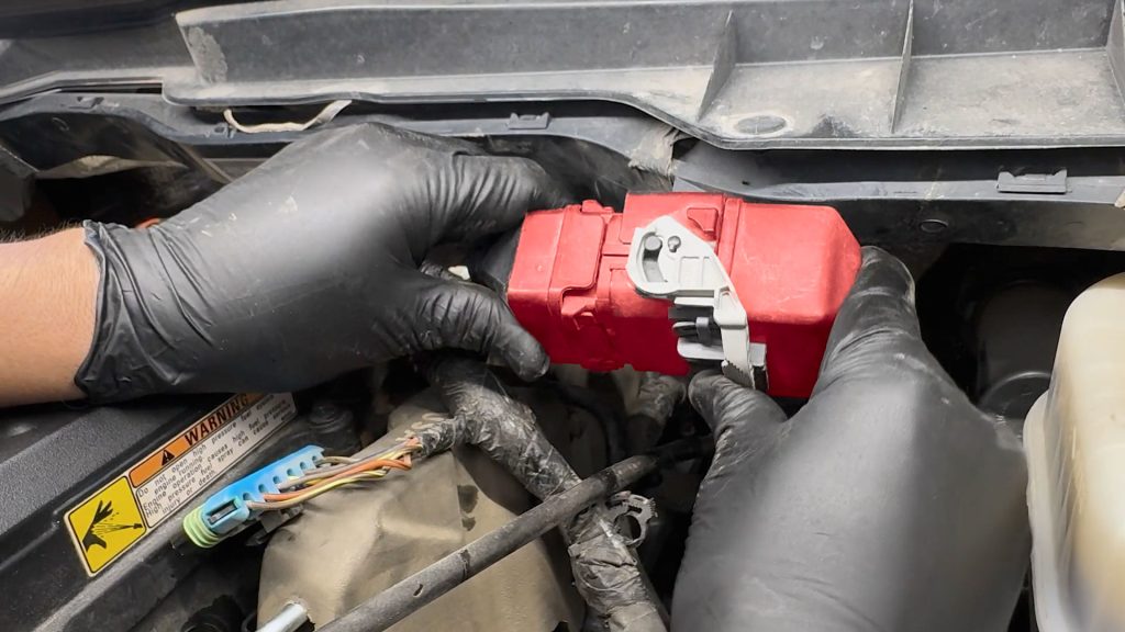
6. Unplug the large rear data plug near the firewall. Slide the white lever to unlock it.
7. With a flat-blade screwdriver, free the cable tie from the firewall.
8. With a flat-blade screwdriver, depress the center of the rear blue/green plug to unlock and remove it.

9. Using a flat-blade screwdriver, gently wiggle the rear PCV hose free from the barb on the cylinder head.
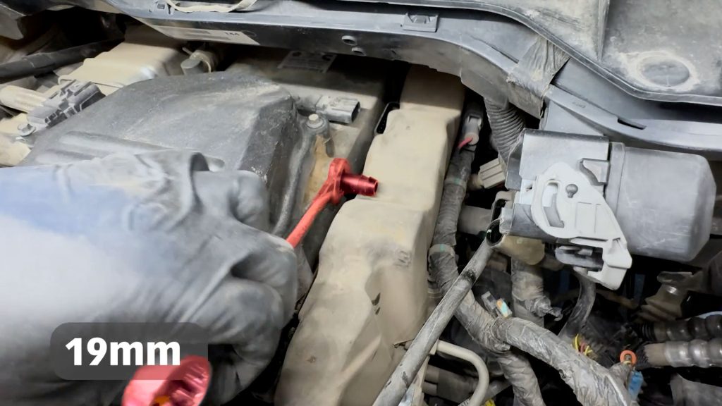
10. Use a 19mm open wrench to remove the rear PCV barb from the cylinder head.
11. Remove the rubber isolator from the fuel rail.
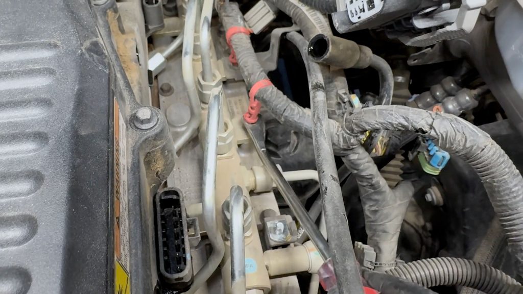
12. Using a flat-blade screwdriver, free the engine harness from the fuel rail studs.
13. There are two cable ties holding the wire harness.
14. With a deep socket, remove the stud that holds down the dipstick tube.
15. With a deep socket, remove the stud that holds down the dipstick tube.
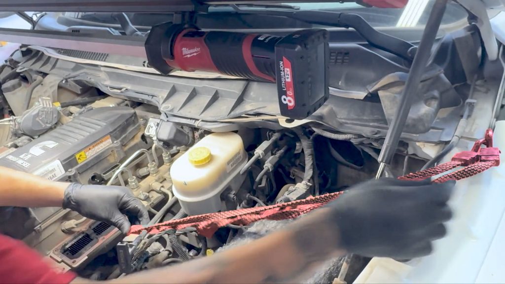
16. Use a bungee cord to hold the dipstick tube out of the way.
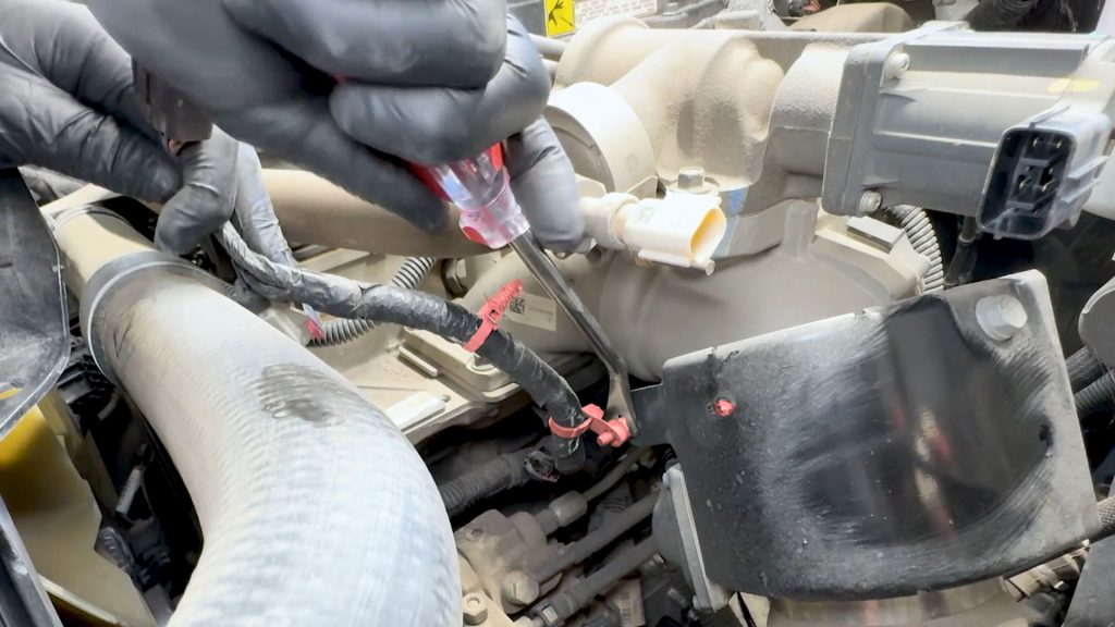
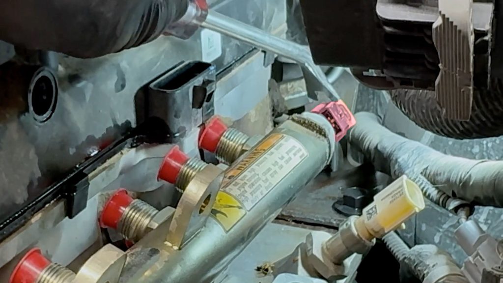
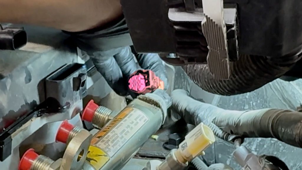
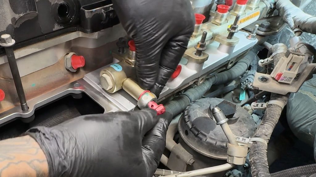
17. At the rear of the fuel rail. Use a flat-blade screwdriver to slide the pink lock and unplug the temperature sensor.
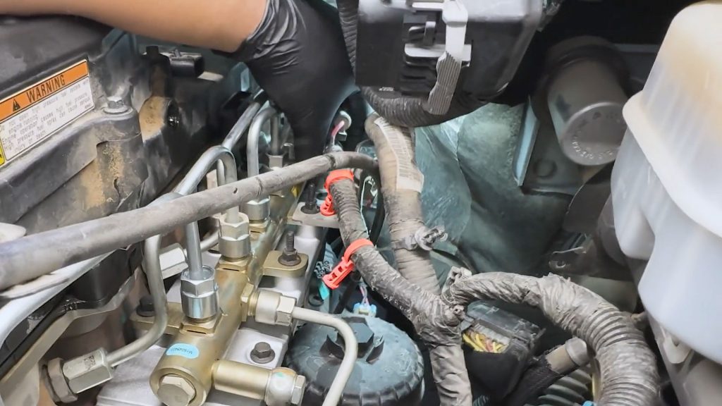
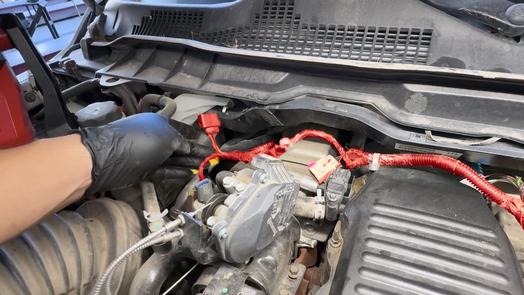
8. Fuel rail and Grid Heater Removal
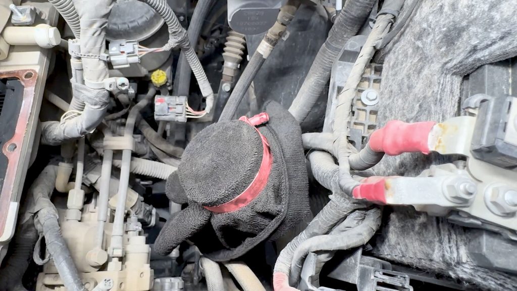
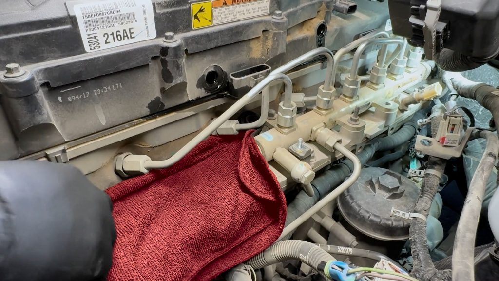
1. Place a rage over the grid heater to prevent debris from entering the intake manifold .
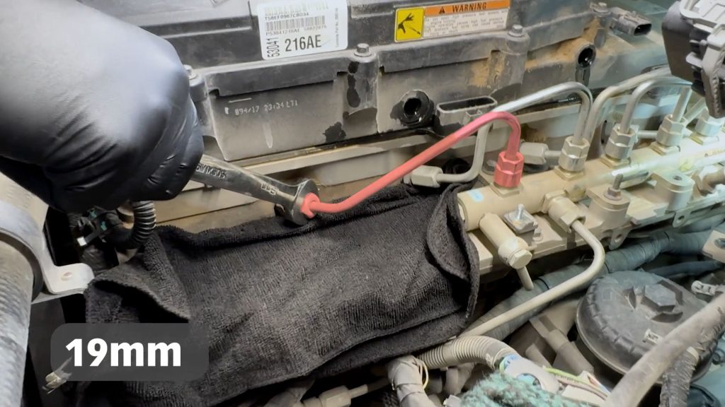
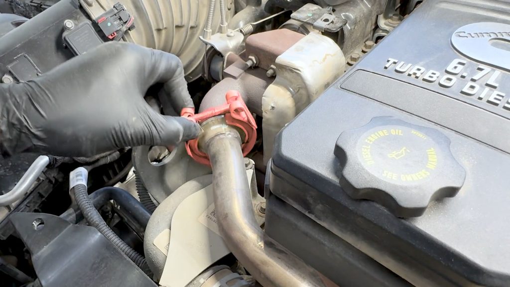
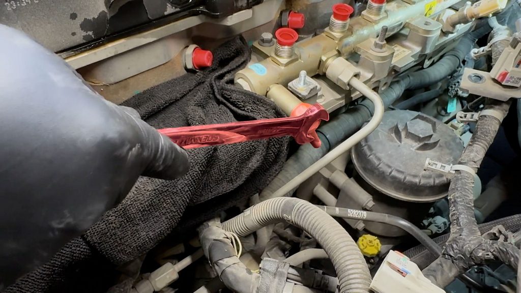
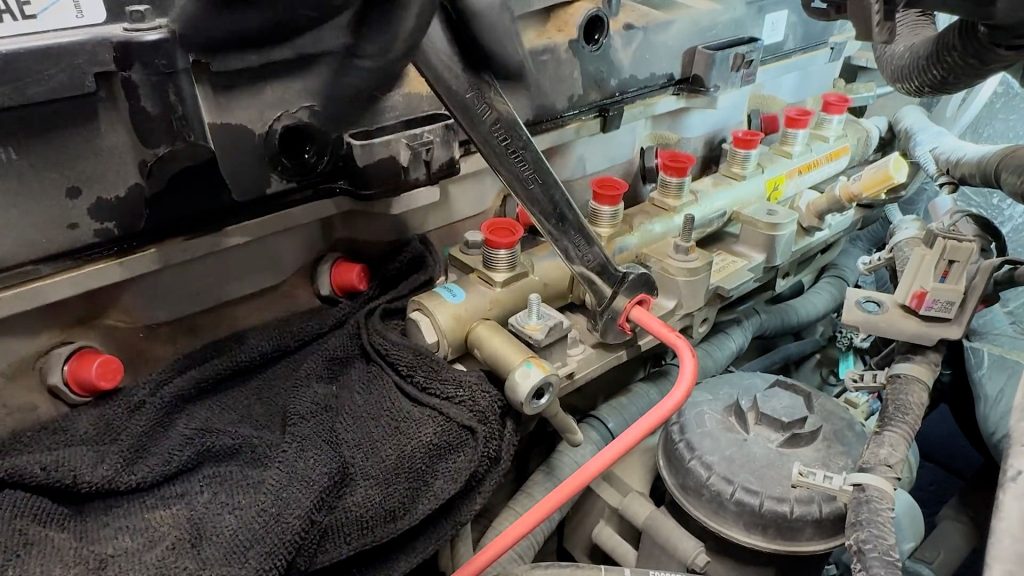
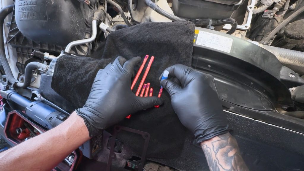
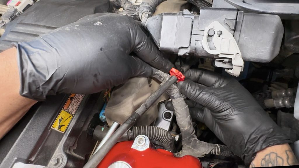
2. With a 19mm wrench, loosen both ends of each fuel line, and set them aside.
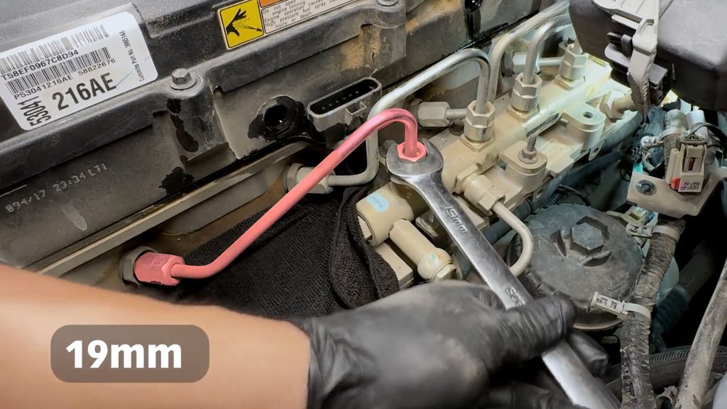
3. With a 19mm wrench, loosen both ends of each fuel line, and set them aside.
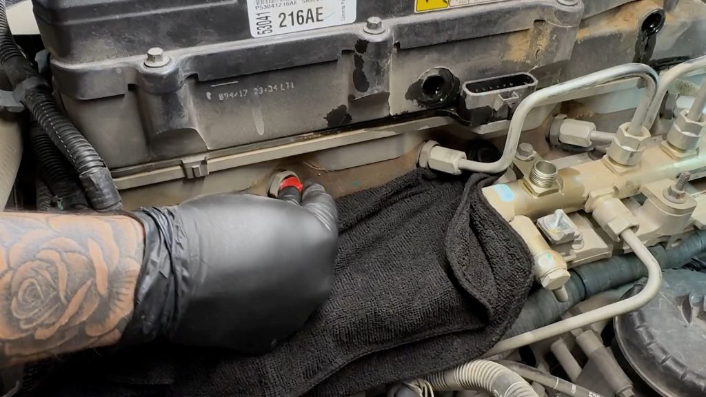
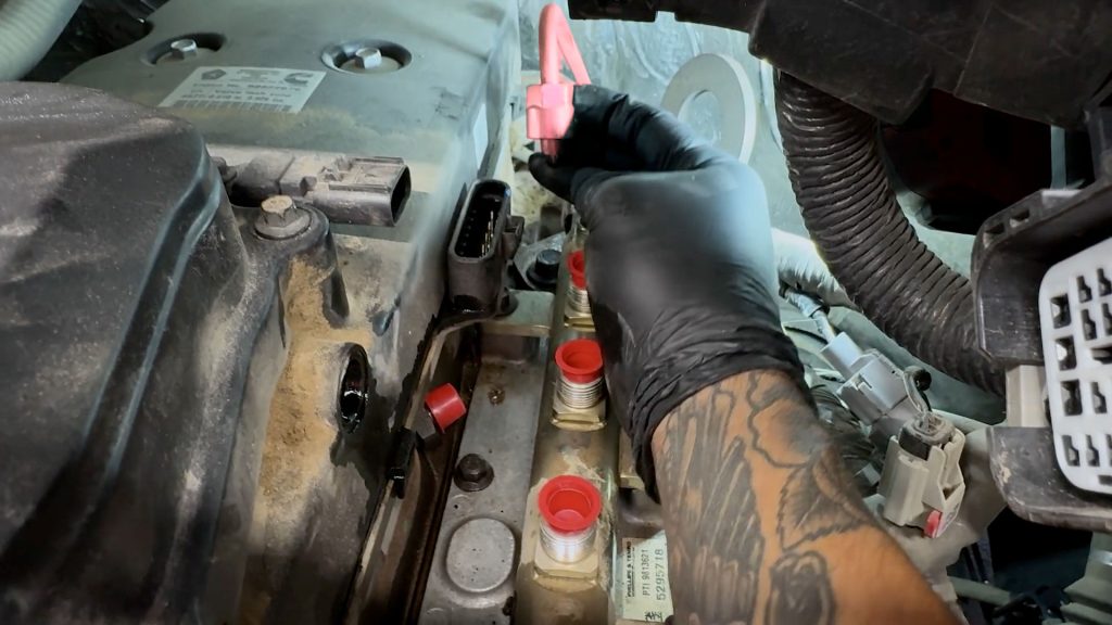
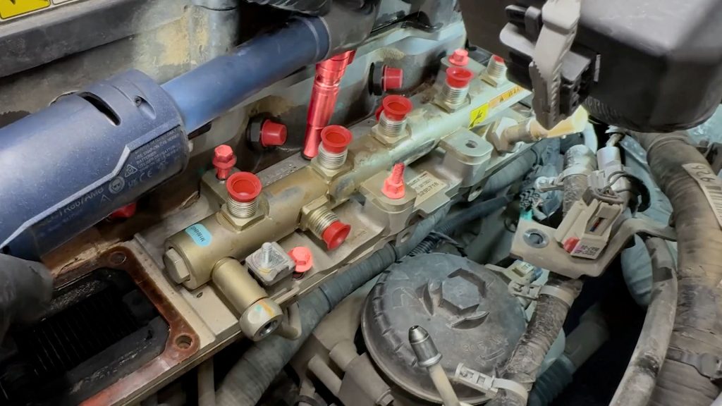
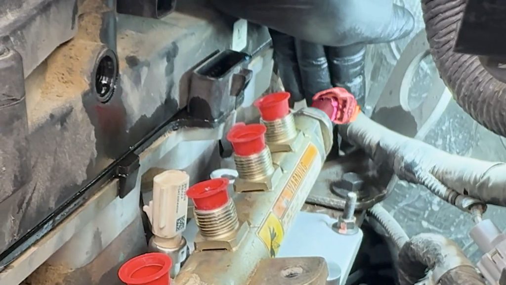
4. After removing each fuel line, use a dust cap over each exposed hole.
Repeat these steps untill reaching the rear #6 fuel line.
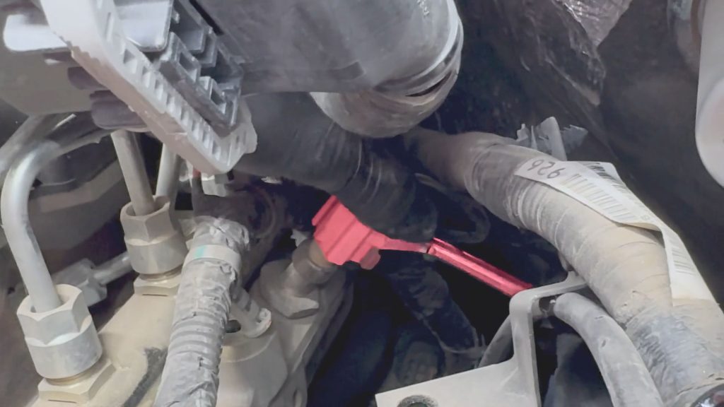
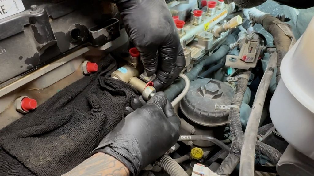
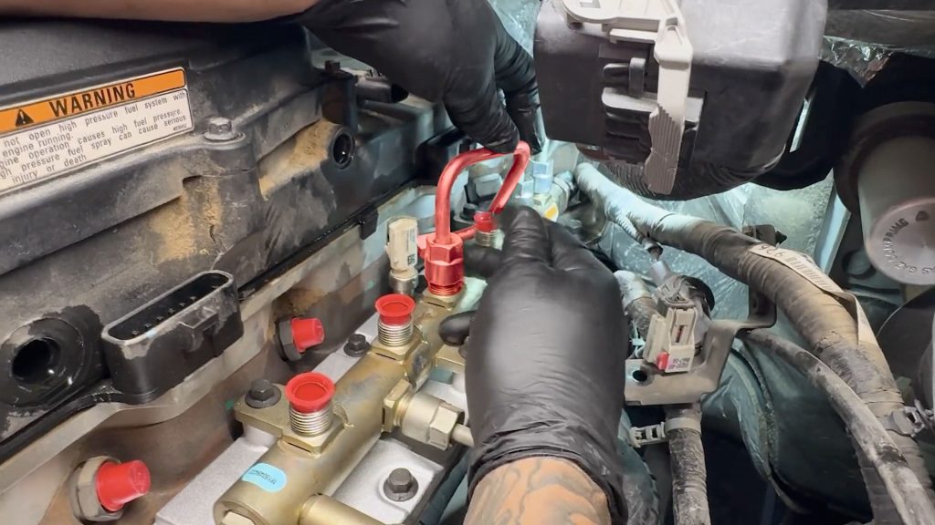
5. The last fuel line is difficult to reach.
You only need to loosen the end of the fuel line that is attached to the cylinder head a few turns. Do not fully remove it.
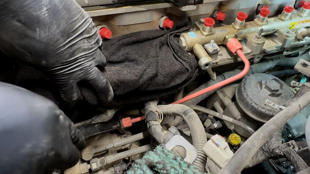
6. Fully loosen the opposite end of the #6 fuel line, and lift the line up and out of the way.
Be sure to cap all exposed fuel line openings.
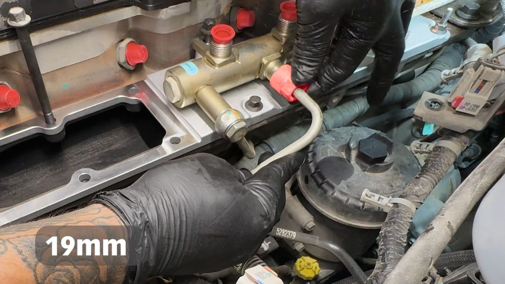
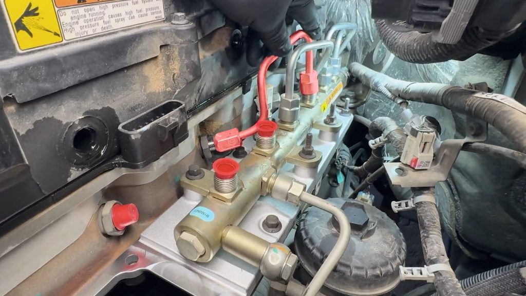
7. Remove the banjo bolt on the front of the fuel rail.
Be sure to catch the banjo bolt washer.
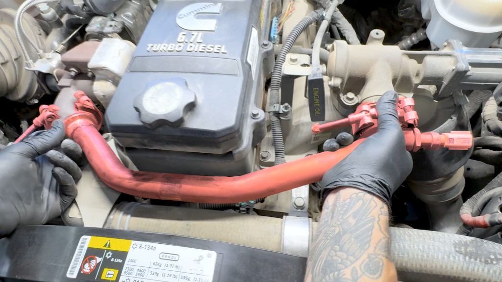
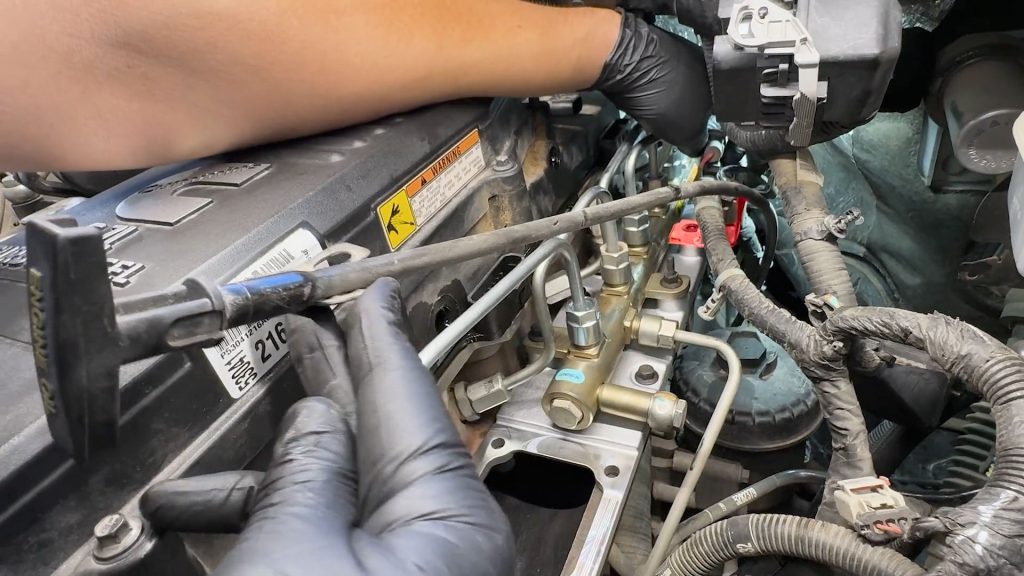
8. With a 19mm wrench, loosen the high-pressure fuel line from the fuel rail.
9. Follow the hard line down to the high-pressure fuel pump and loosen that end slightly.

10. This will allow you to rotate the hard line out of the way.
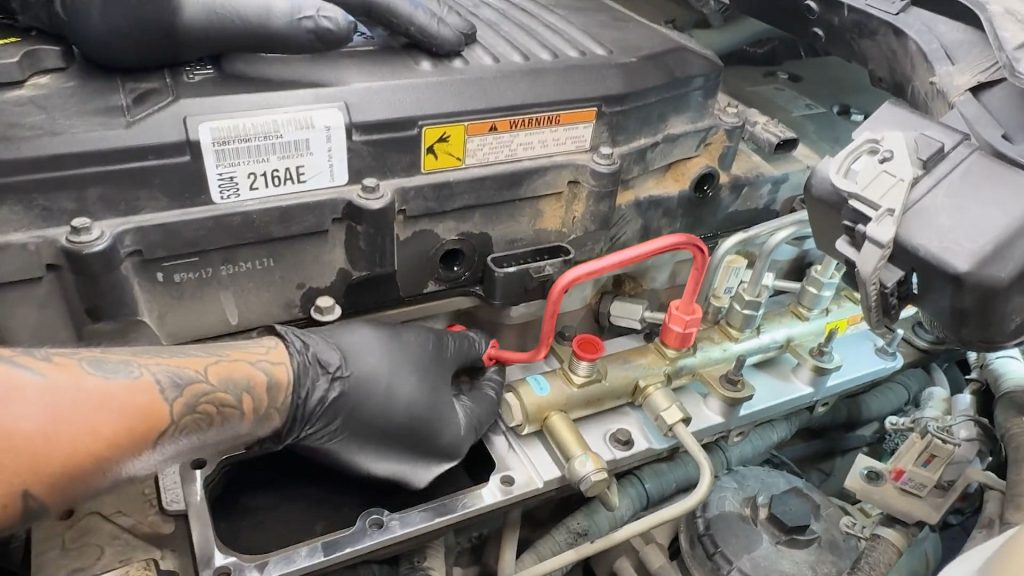
11. With a 10mm deep socket, remove the remaining bolts that hold down the fuel rail and grid heater plate.
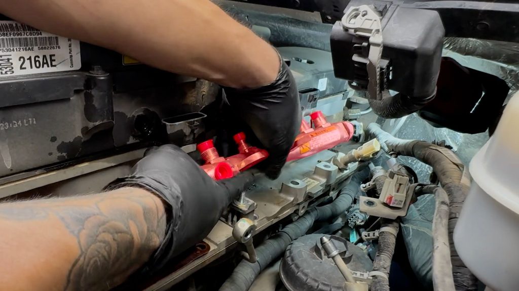
12. With the bolts removed, reach for the fuel rail and locate the pressure sensor at the rear.
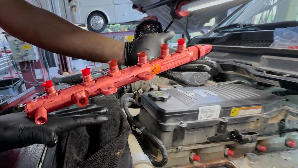
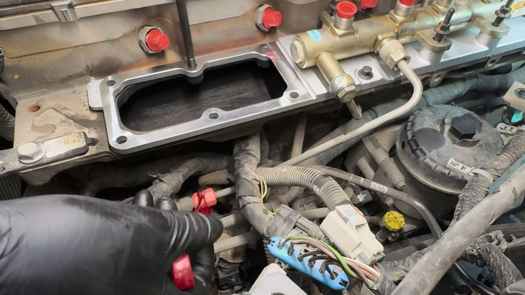
13. Remove the fuel rail, and set it aside.
14. Remove the grid heater and set it aside.
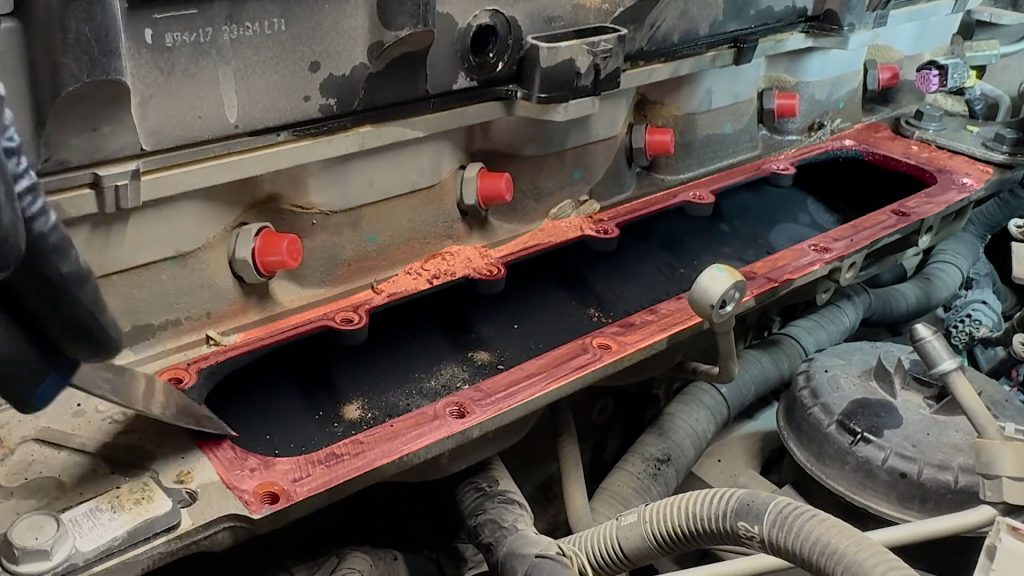
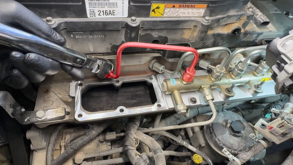
15. Carefully remove any old gasket material left on the intake manifold surface.
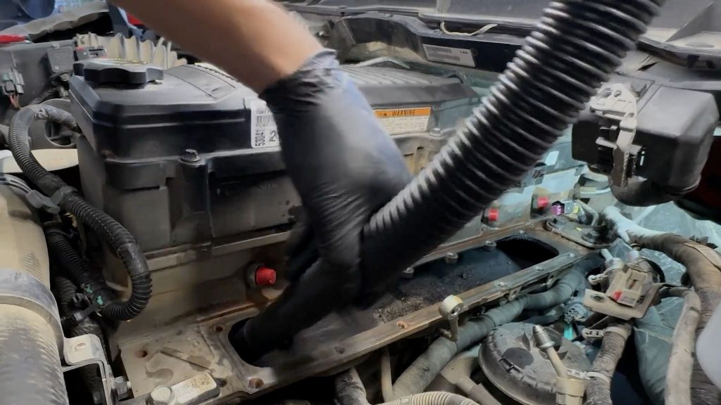
16. Use a shop vac to remove any remaining debris that may have fallen in the intake manifold.
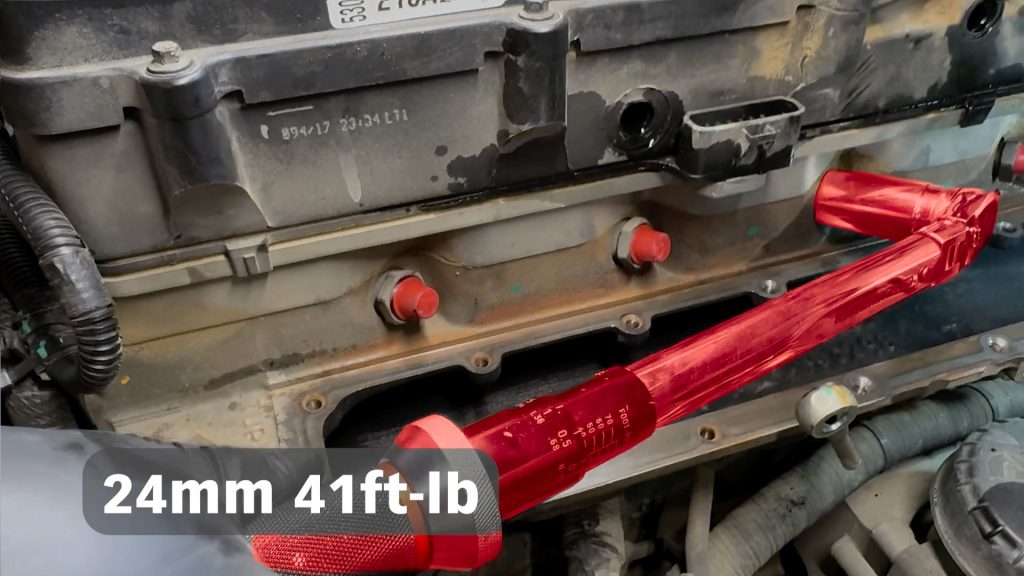
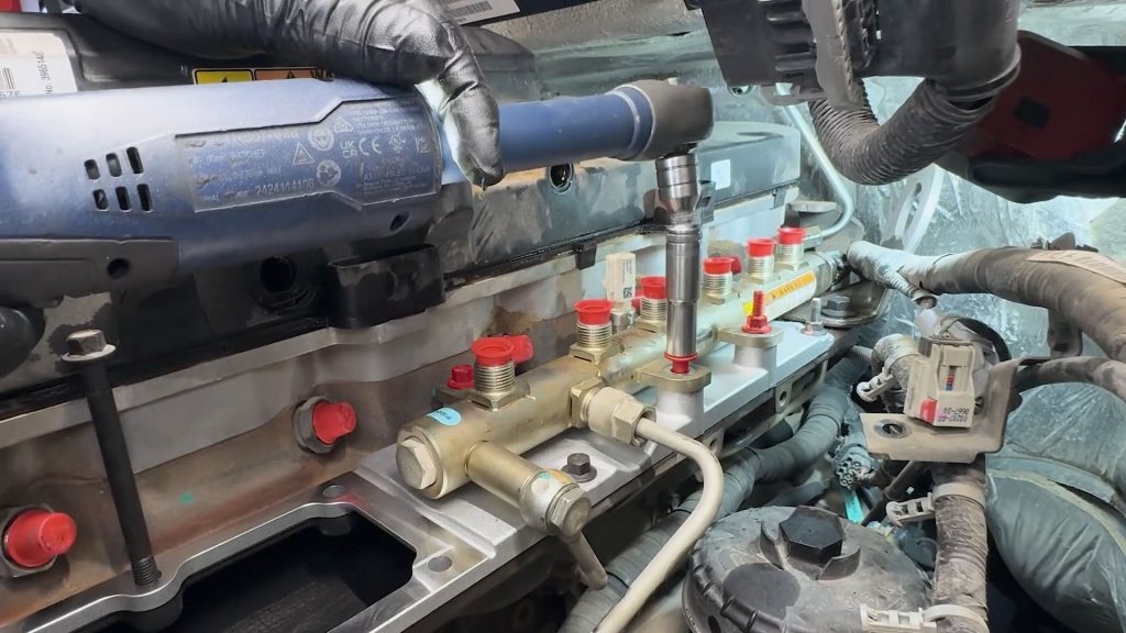
17. With a 24mm socket, Re-torque each of the 6 fuel injector tubes to 41 ft-lb. Use a 24mm crows foot for the #6 fuel line.
This step is critical to prevent possible leaks as these injector tubes may have backed out during the removal of the fuel injector lines.

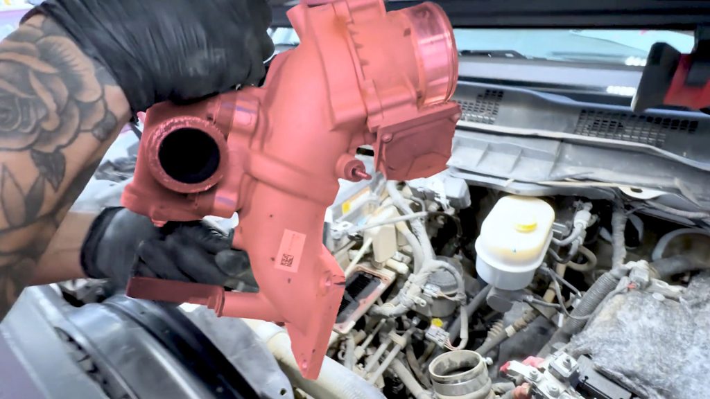
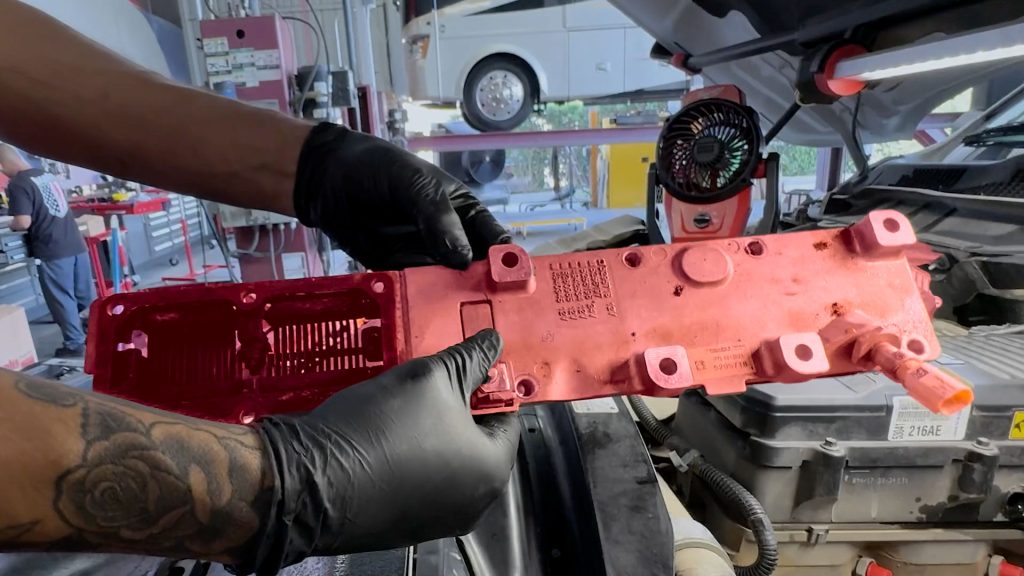
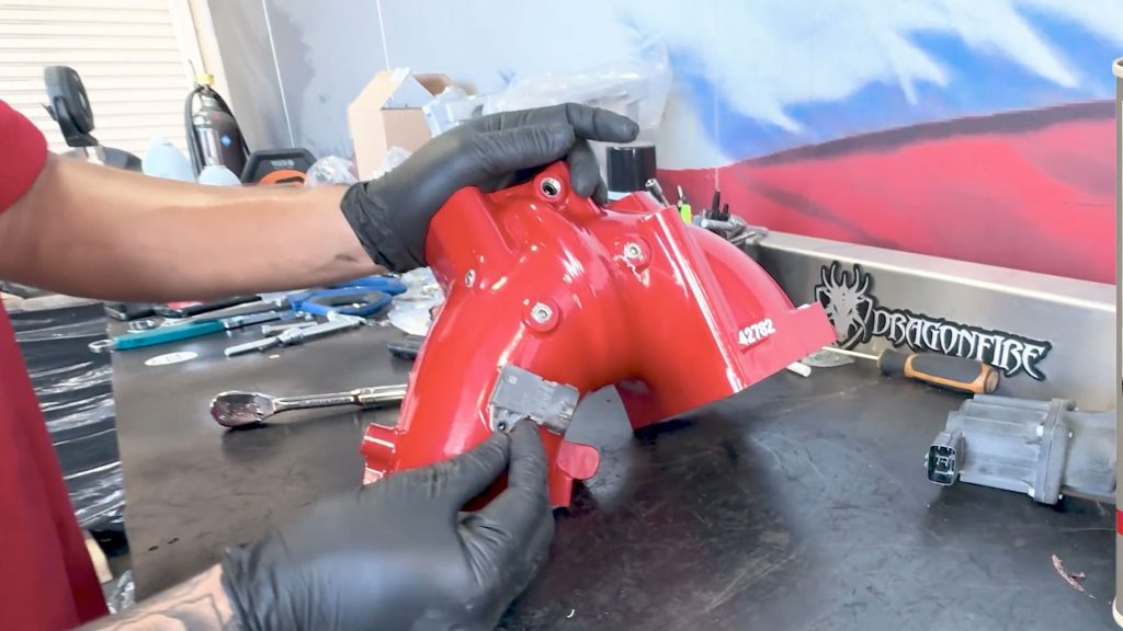
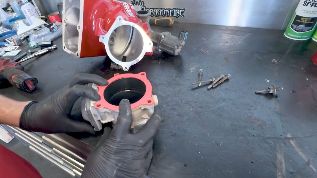
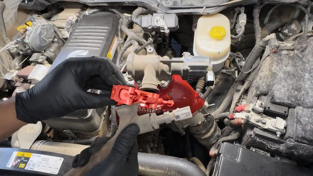
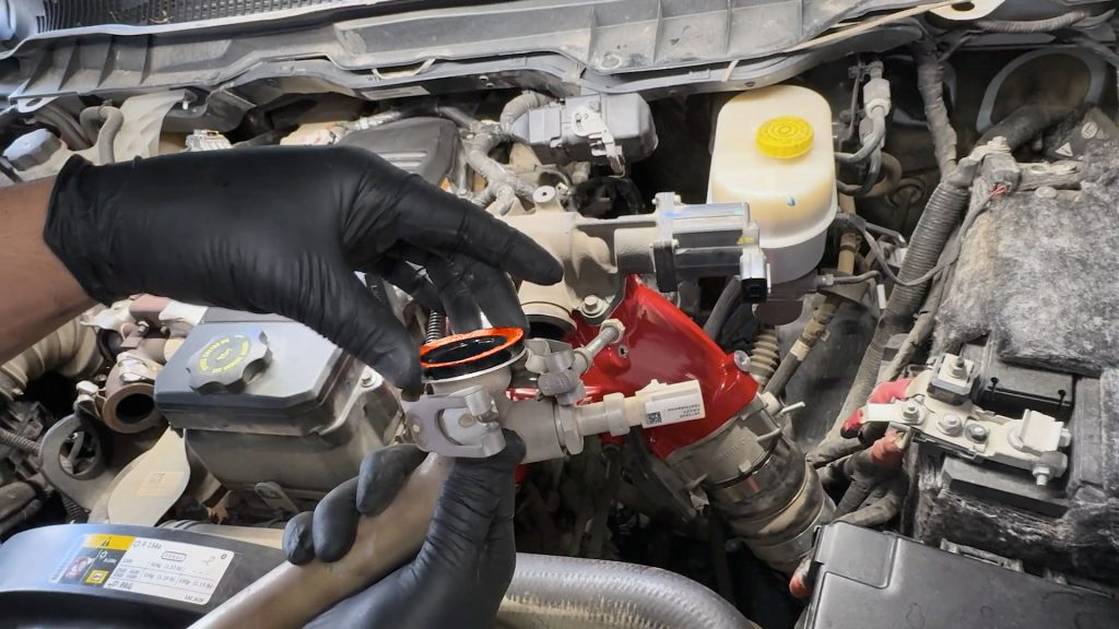
9. Preparing the Monster-Ram
1. Using a 10mm deep socket, remove the four bolts that hold the EGR valve in place on the stock intake elbow.
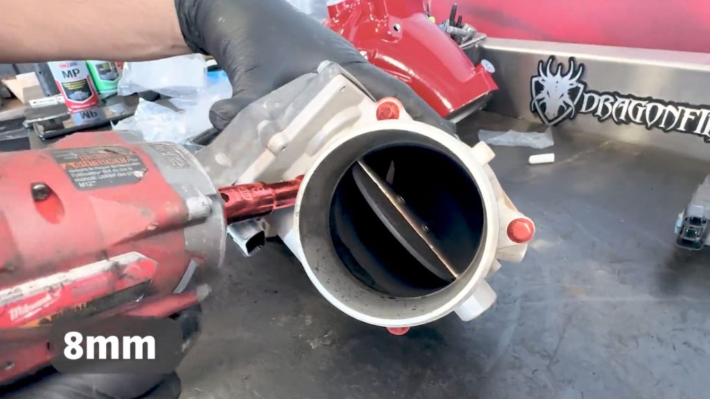
2. With an 8mm deep socket, remove the 4 bolts that hold the throttle body onto the stock intake elbow.
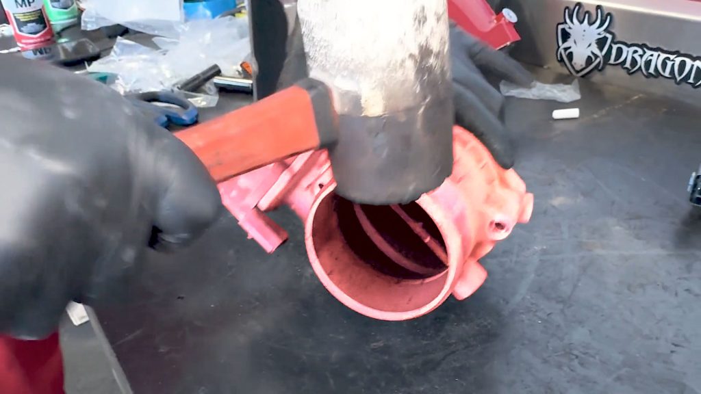
3. Given the vehicle’s age, the throttle may still be stuck after removing the bolts. A tap with a mallet will break it loose.
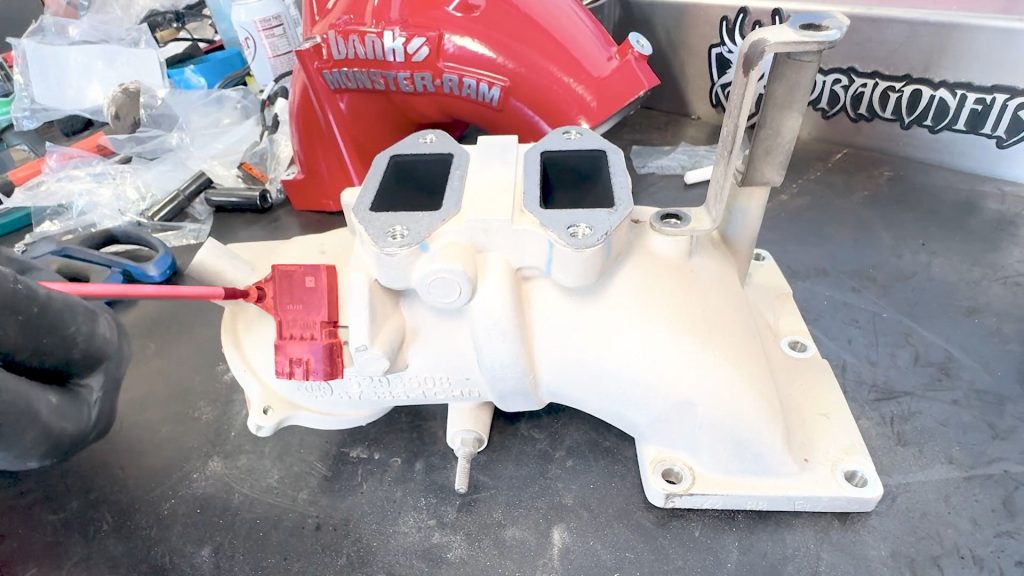
4. With a torx bit screw driver, remove the MAP sensor from the side of the stock intake elbow.
5. The MAP sensor can get filled with soot after years of use. Now is a good time to clean the sensor with some Mass Air Flow cleaner or replace it.
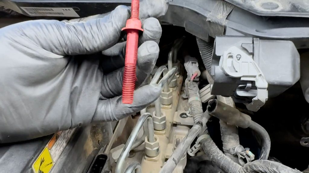
6. On the front of the stock intake elbow, remove the stud. It will be transferred over to the Monster-Ram.
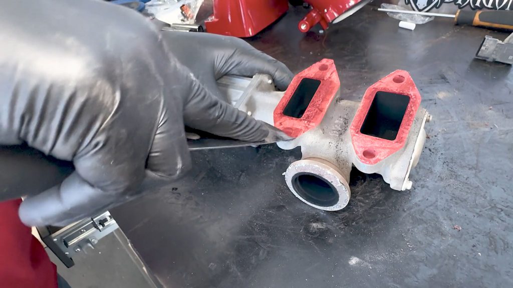
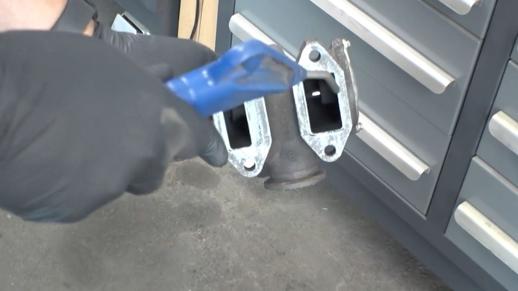
7. Carefully remove any extra gasket material left on the EGR valve.
8. Carefully remove any extra gasket material left on the throttle valve.
9. Blow out any remaining debris with compressed air.
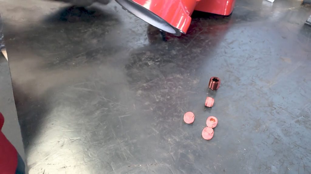
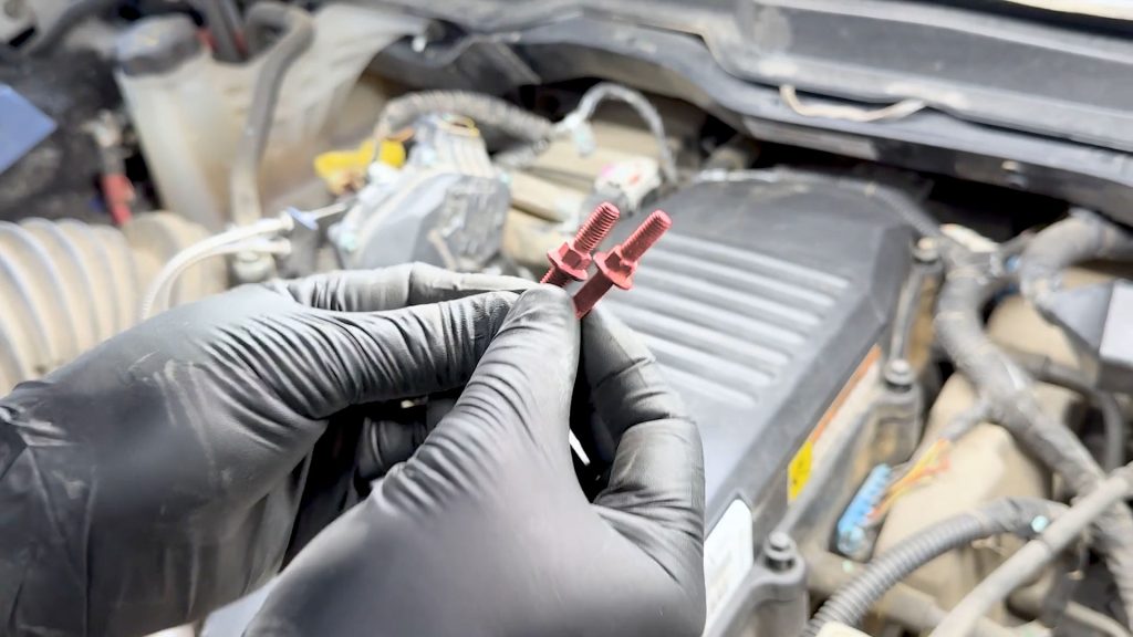
10. Locate the 4 NPT plugs and the larger black plug.
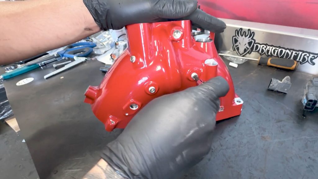
11. Thread the 4 smaller NPT plugs into the rear and side of the Monster-Ram.
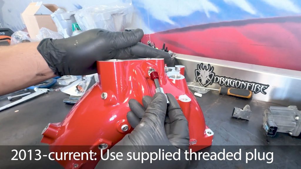
12. The larger black plug threads into the EGR ring.
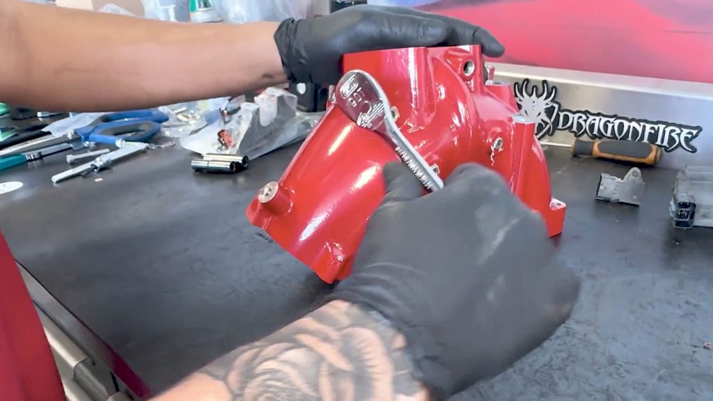
13. Snug down all 4 NPT plugs; the top larger one will fully bottom out.
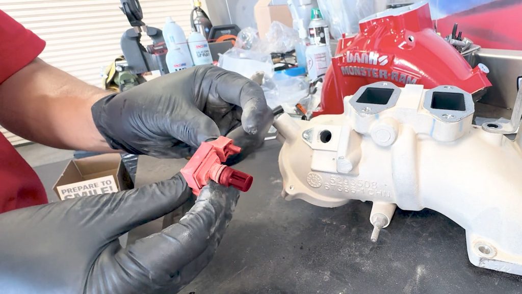
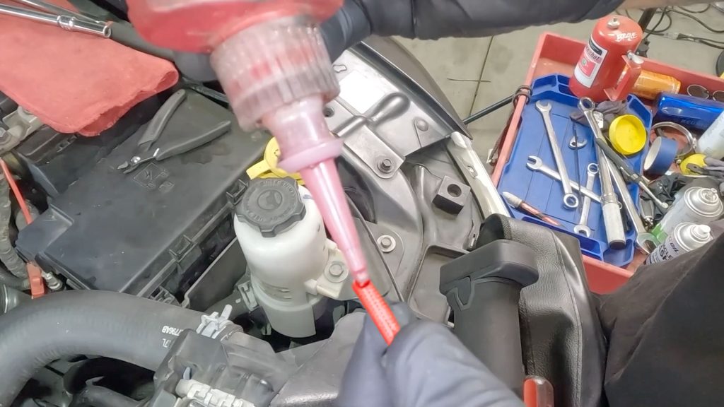
14. Transfer the MAP sensor into the Monster-Ram.
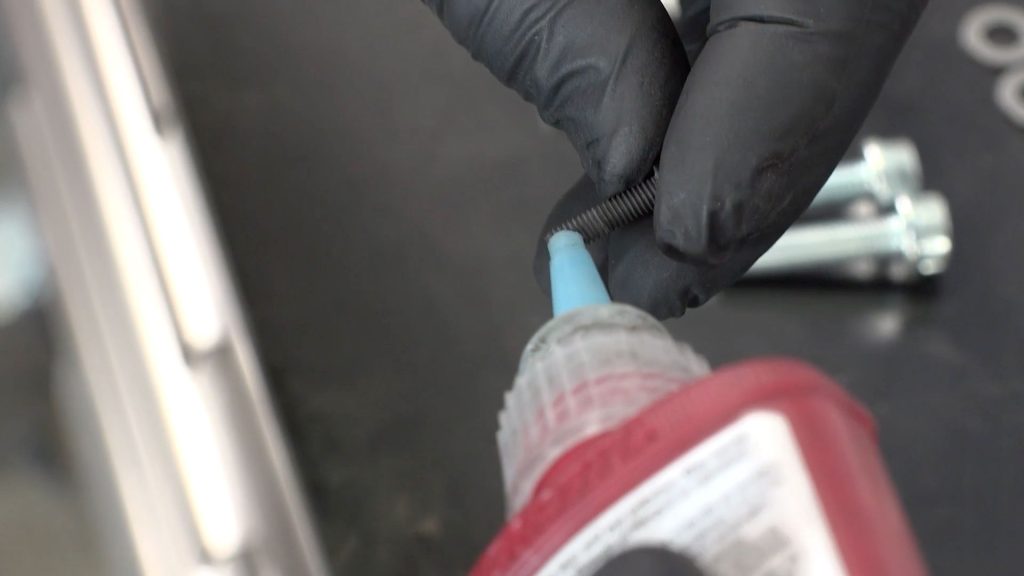
15. Apply a drop of thread locker to the screw.

16. Tighten the screw with a Torx bit screwdriver.
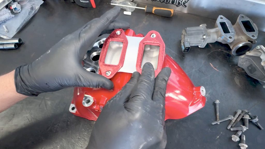
17. Place the two EGR gaskets on top of the Monster-Ram.
18. Grab the EGR valve and accompanying bolts.
19. Start threading the four bolts in by hand.

20. Then snug them down.
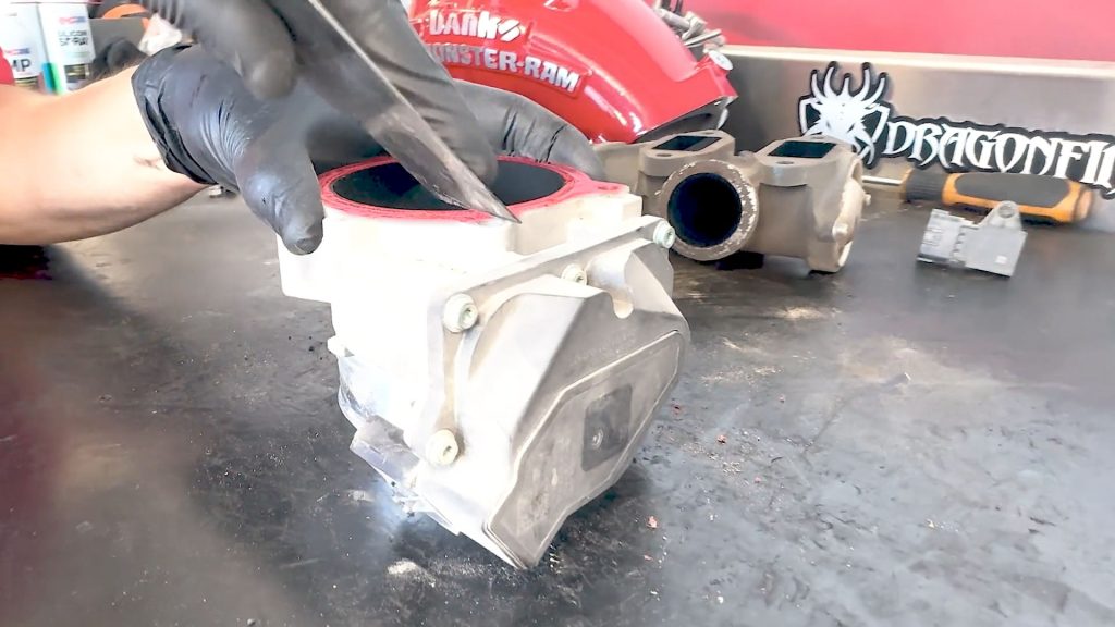
21. Place the supplied gasket on the back side of the throttle body.

22. Install the throttle body onto the Monster-Ram and snug down the 4 bolts. (7.5 ft-lb | 89 in-lb)
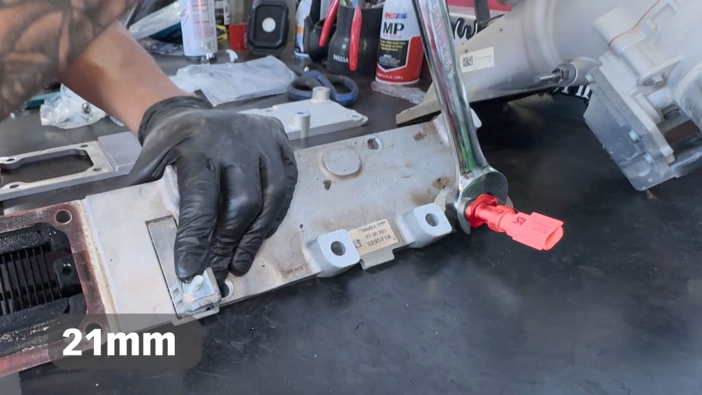
9. High Flow Cast Intake Plate & Fuel Rail Install
1. With a 21mm open-ended wrench, remove the temperature sensor from the factory intake manifold plate.
2. With the sensor removed, now is a good opportunity to clean off any carbon buildup on the sensor.
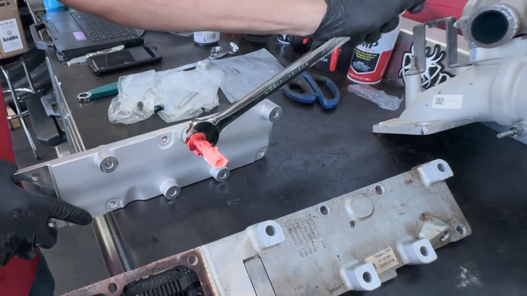
3. Swap the temperature sensor into the Banks cast high-flow intake plate. Snug it down with a 21mm open-ended wrench.
Take care not to over-tighten the sensor, as the steel threads could damage the aluminum.
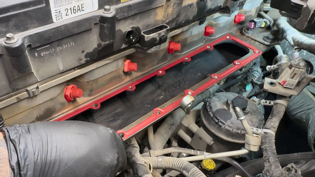
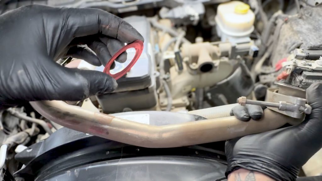
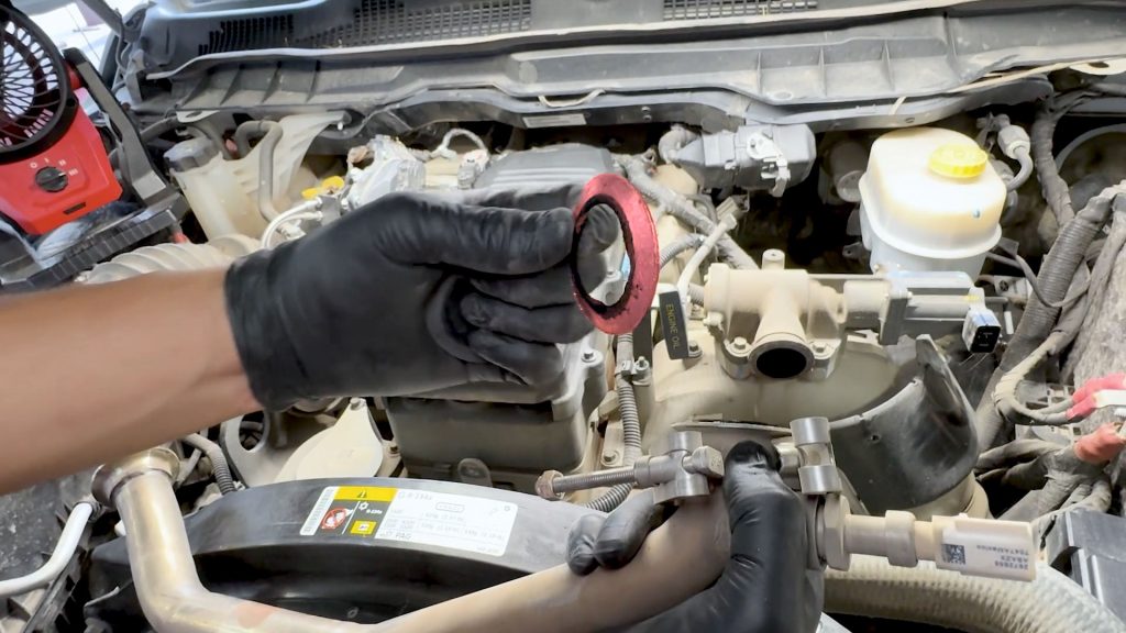
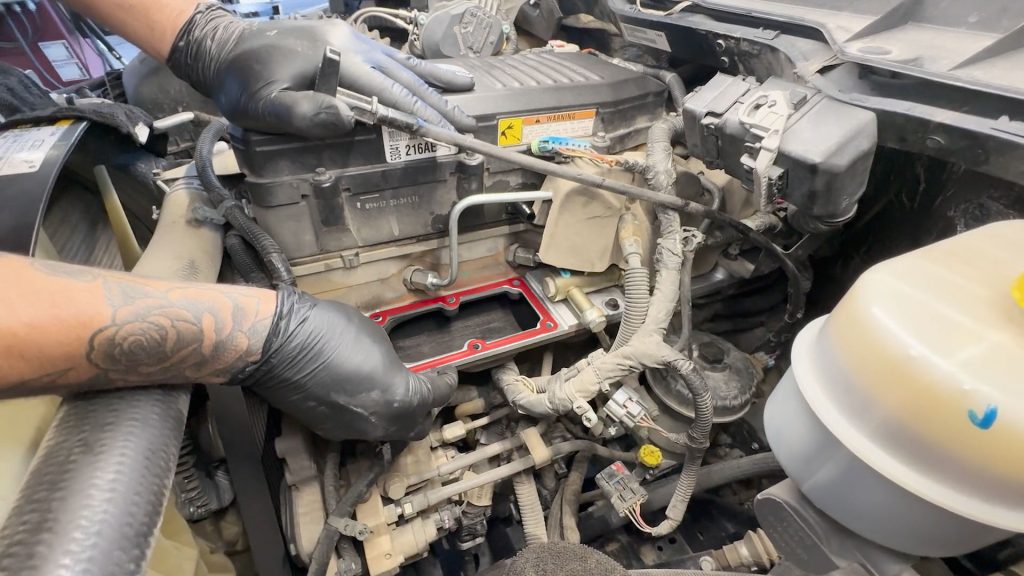
4. Place the supplied gasket on the intake manifold.
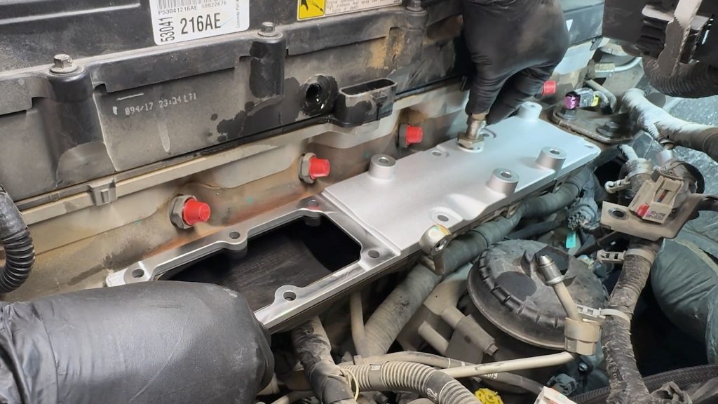
5. Place the Banks high flow plate on the gasket.
6. Use one of the stock bolts to act as a guide to keep the gasket and plate aligned.
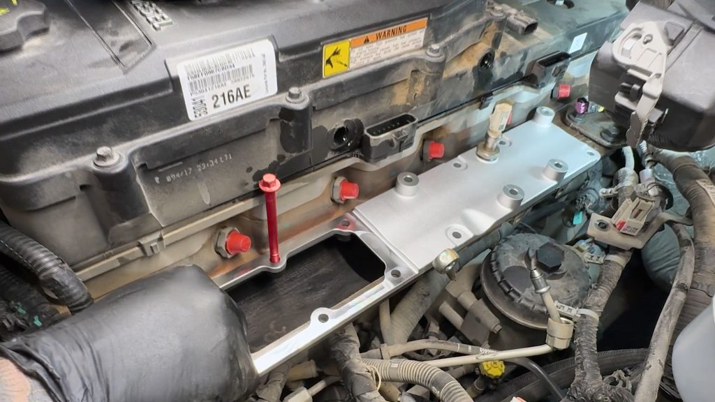
7. Grab the 3 short bolts and the stud that held the intake manifold plate down. Apply a drop of threadlocker to each.
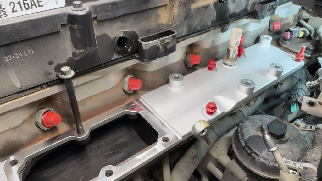
8. Thread them into the four spots where the fuel rail spacers are not. The one with the stud goes in the far right corner.
9. Snug the four bolts down; they will be torqued later.
10. Bring the fuel rail back over to the truck and line it up with the four spacers on the high-flow plate.
11. Plug in and lock the sensor at the rear of the fuel rail.
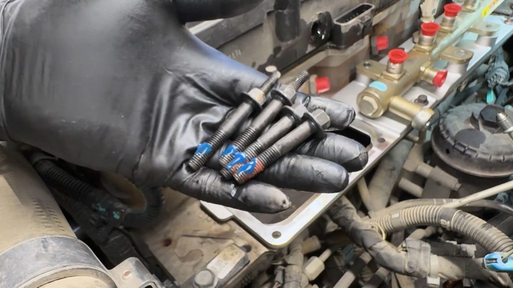
12. Apply a drop of thread locker to the three bolts and stud for the fuel rail.
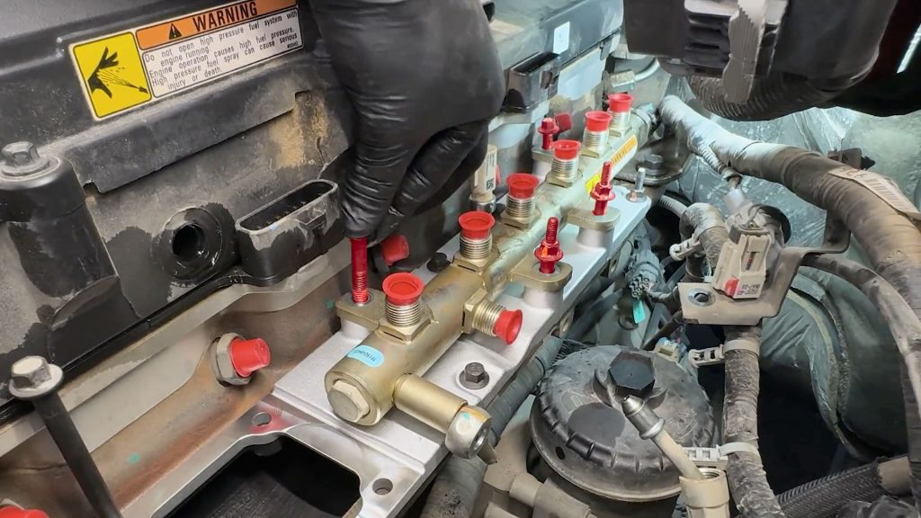
13. Thread them in by hand first, leave them loose until the hard lines from the fuel pump are attached.
The studs go on the driver side, away from the cylinder head.
14. Carefully slide the washer back into place between the fuel rail and the fuel line.
15. Then run the banjo bolt and its washer through into the fuel rail. Tighten the bolt by hand for now.
16. Rotate the high-pressure fuel line from the pump back into the fuel rail. Hand-tighten it for now.
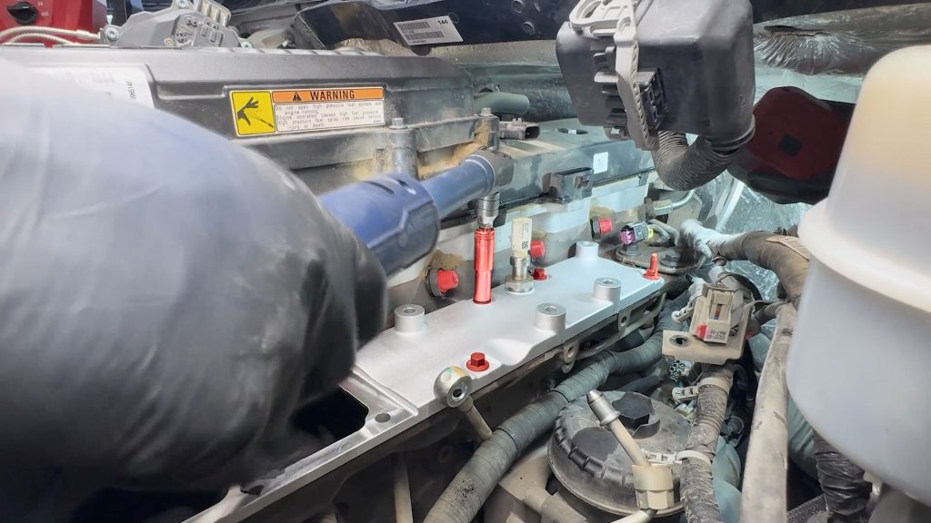
17. With a 19mm wrench, snug down the lower nut on the high-pressure fuel line. This will be torqued down later.
18. With a 10mm deep socket, snug down the four bolts that hold the fuel rail down.
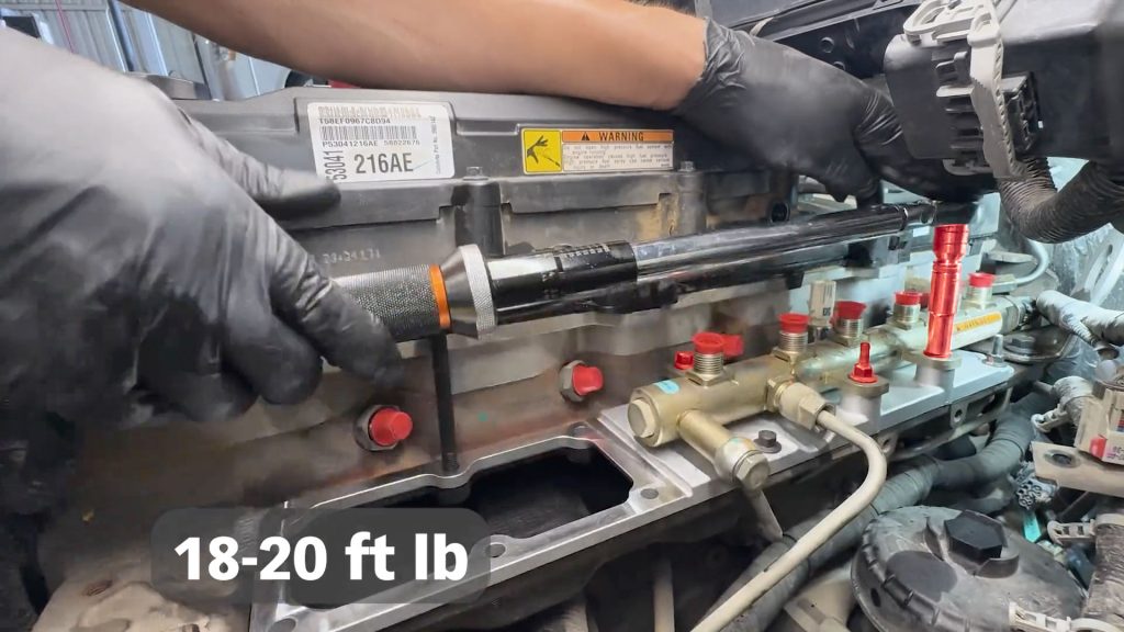
19. Torque down all eight fuel rail and intake plate bolts to 18-20 ft lb.
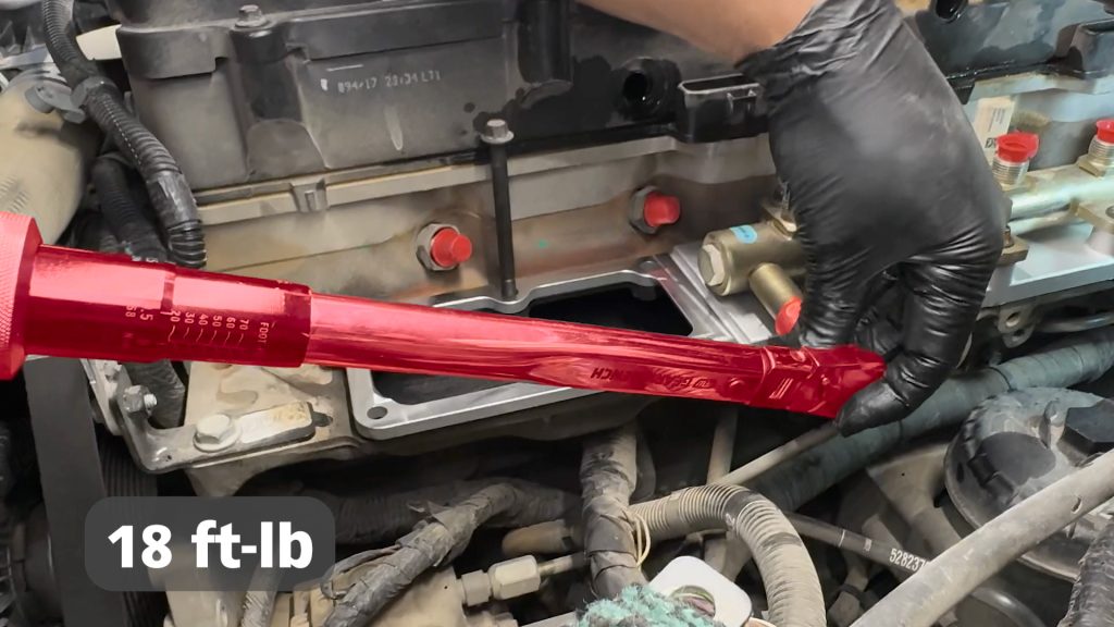
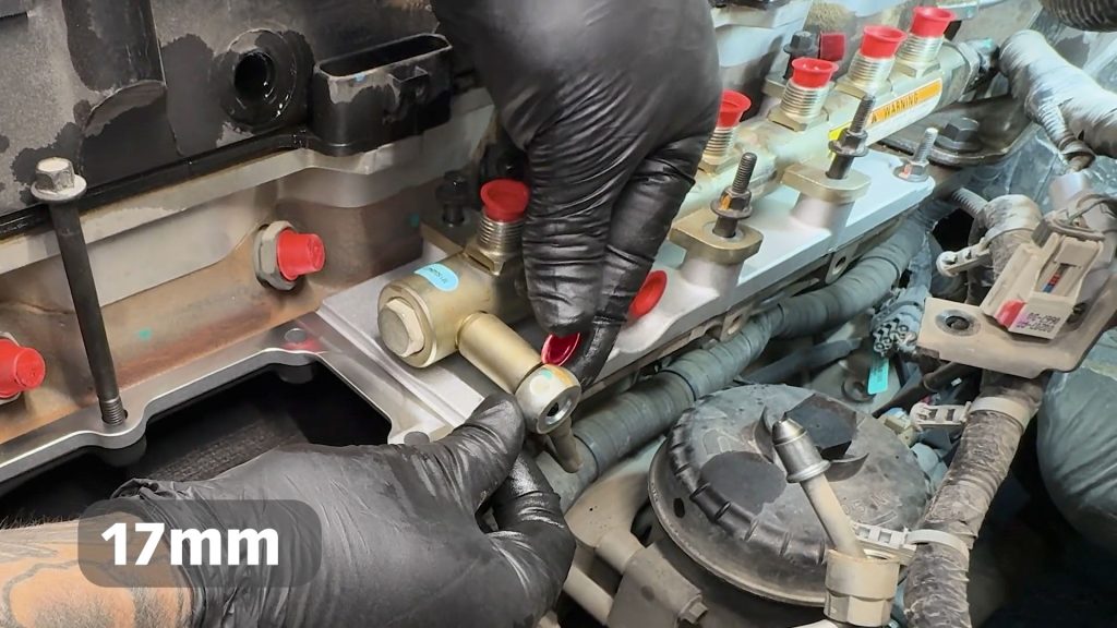
20. With a 17 mm socket, torque the banjo bolt to 18 ft-lb.
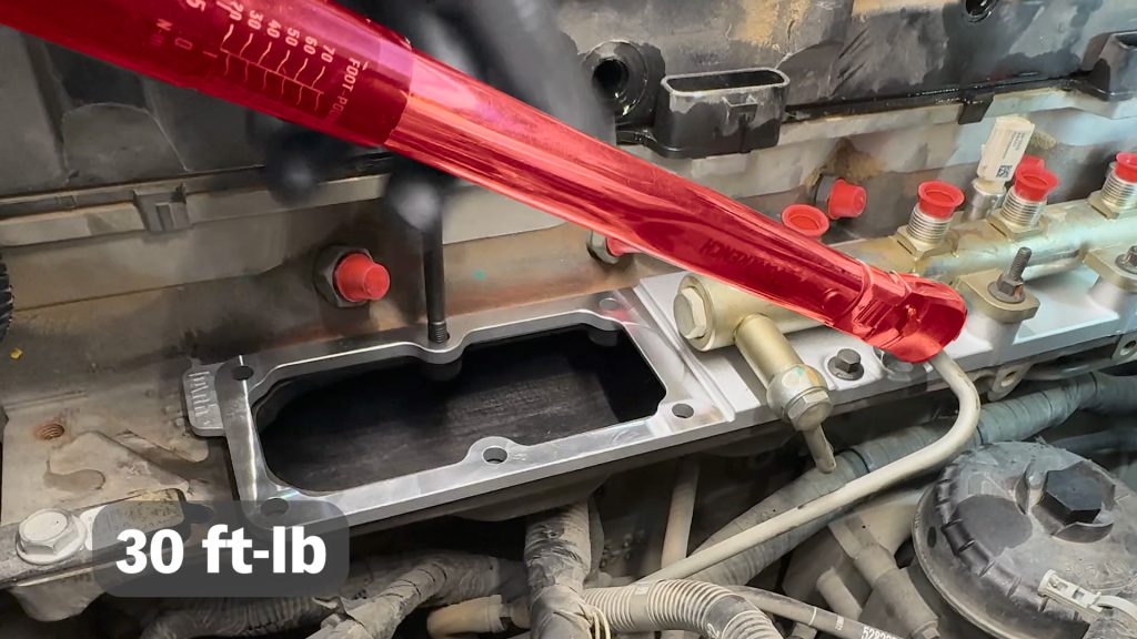
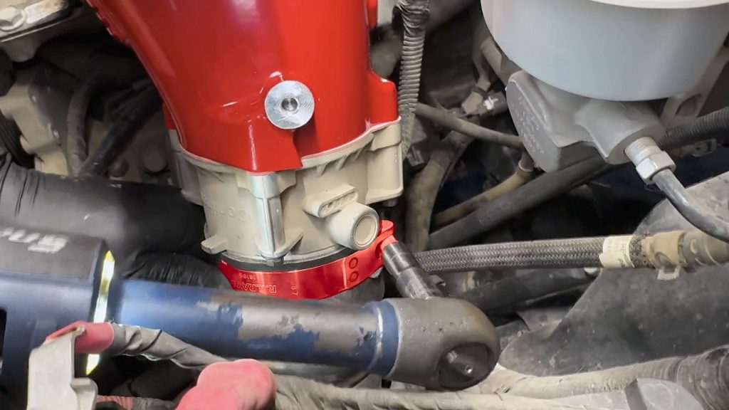
21. With a 19 mm crows foot attachment, torque the high-pressure fuel line to the fuel rail to 30 ft-lb.
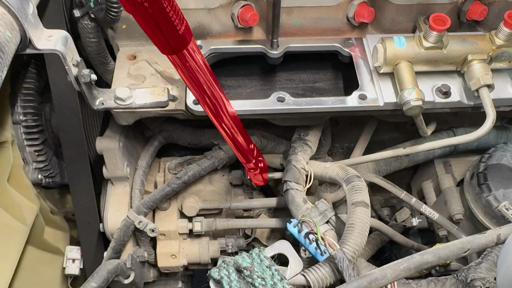
22. Don’t forget to torque the other end of the fuel line by the fuel pump.
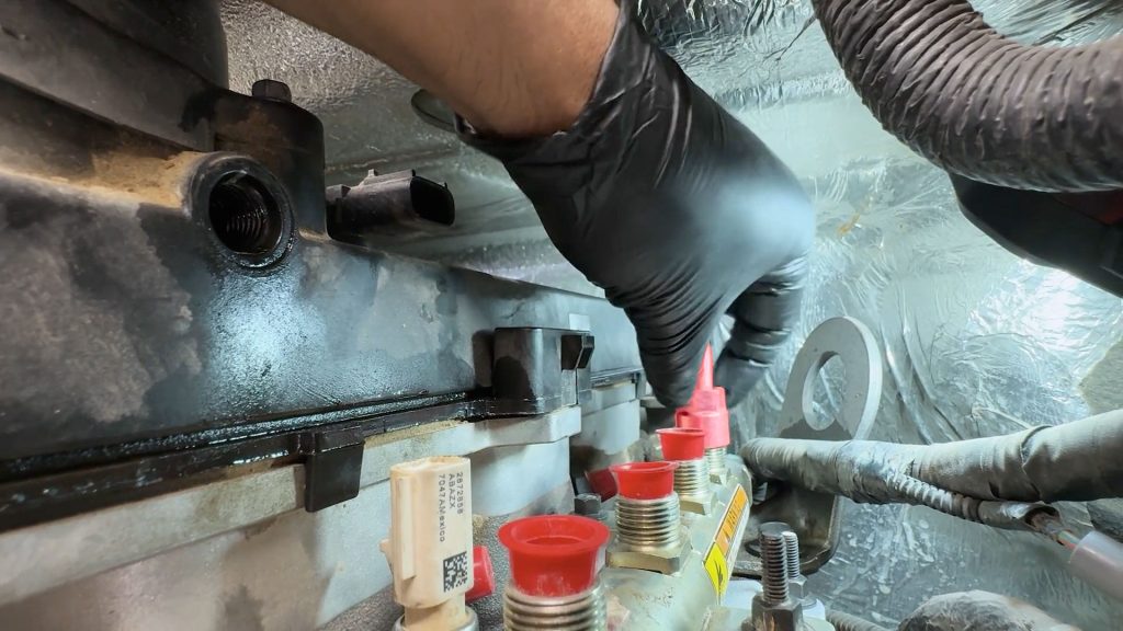
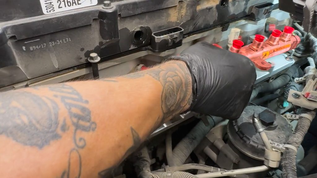
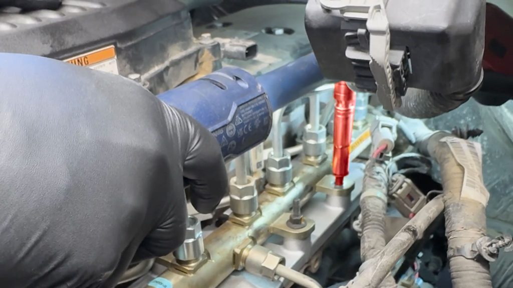
23. Swing the #6 fuel line back down onto the fuel rail and start threading it back by hand.
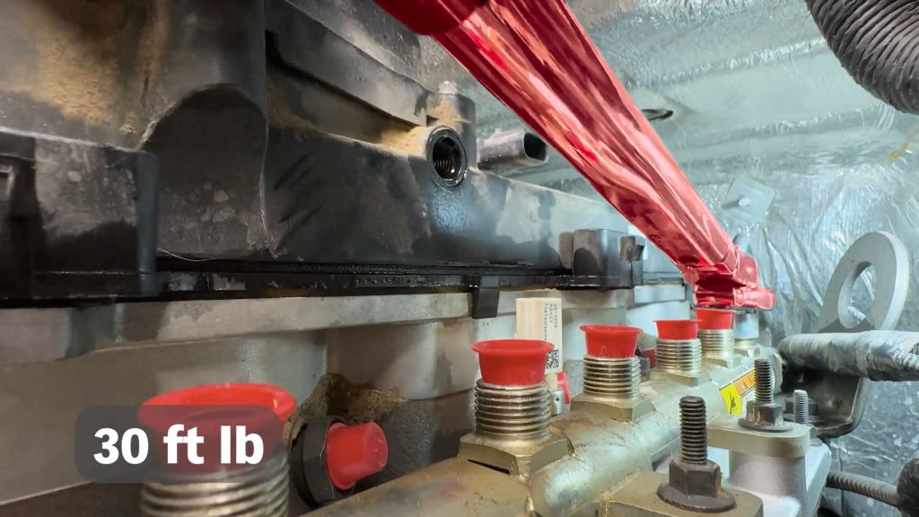
24. With a 19mm crows foot attachment, torque both ends of the #6 fuel line to 30 ft-lb.
25. Continue down to the #5 fuel line.
26. With a 19mm crows foot attachment, torque both ends of the #5 fuel line to 30 ft-lb.
27. Continue down to the #4 fuel line, with a 19mm crows foot attachment, torque both ends to 30 ft-lb.
28. Continue down to the #3 fuel line, with a 19mm crows foot attachment, torque both ends to 30 ft-lb.
29. Continue down to the #2 fuel line, with a 19mm crows foot attachment, torque both ends to 30 ft-lb.
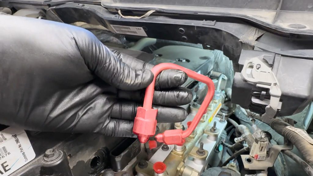
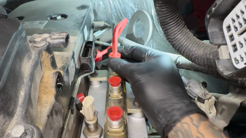
30. Last, install the #1 fuel line. With a 19mm crows foot attachment, torque both ends to 30 ft-lb.
31. Plug in the Banks thermocouple extension harness between the sensor and the factory plug, slide the pink tabs over to lock them.
32. Temporarily remove the 2nd stud from the fuel rail.
33. Swing the dip-stick tube back over, and secure it with the fuel rail stud.
Secure it with the fuel rail stud.
34. Reattach the wire looms cable ties to the two studs on the fuel rail.
35. Reattach the wire looms cable ties to the two studs on the fuel rail.
13. Breather Hoses and Wire Loom
1. Reattach the rear PCV barb, snug it down with a 19mm open-end wrench.
2. Reattach the rear PCV barb, snug it down with a 19mm open-end wrench.
3. Reattach the front PCV barb, snug it down with a 19mm open-end wrench.
4. Start routing by tucking it under the dipstick tube.
5. Continue routing the wire loom back around the engine.
6. Plug in the rear of the two blue/green plugs.
7. Plug in and lock the rear white plug into the valve cover.
8. Do the same for the plug on the passenger side. Plug it in and slide the lock in place.
9. Plug in the EGR valve actuator and slide the tab to lock it.
10. Plug in the EGR valve actuator and slide the tab to lock it.
11. Reattach the cable tie back onto its stud.
12. Reconnect the large data cable on the driver’s side, and swing the lever back into the locked position.
13. Secure the harness with its plastic cable tie.
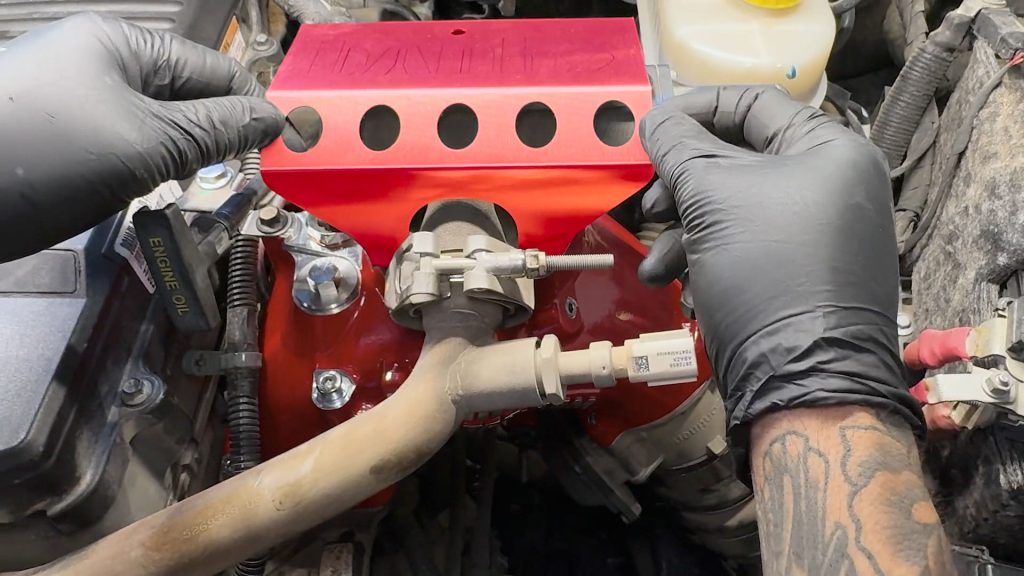
13. Monster-Ram Install
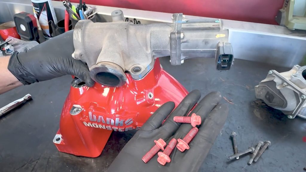
1. Slide a washer on the 4 bolts which dont have a flanged head on them, and apply some blue Loctite to all 6.
2. Uncover the boost tube, set the clamp back on it.
3. Uncover the boost tube, set the clamp back on it.
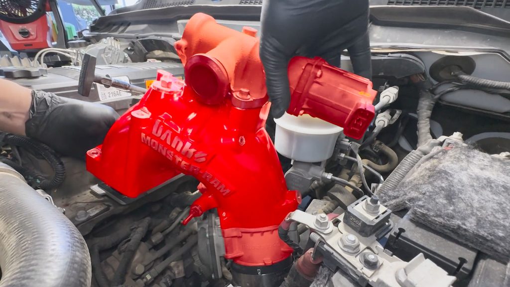
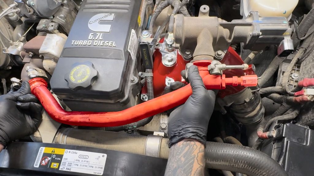
4. Bring the assembled Monster-Ram over to the truck. Slide the boost tube on first, then align the bolt holes over the gasket.
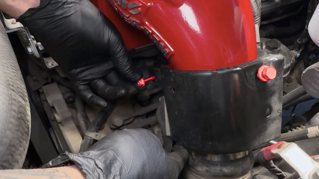
5. By hand, insert the longer bolts first, and thread them in by hand. Then do the two short ones in the front.
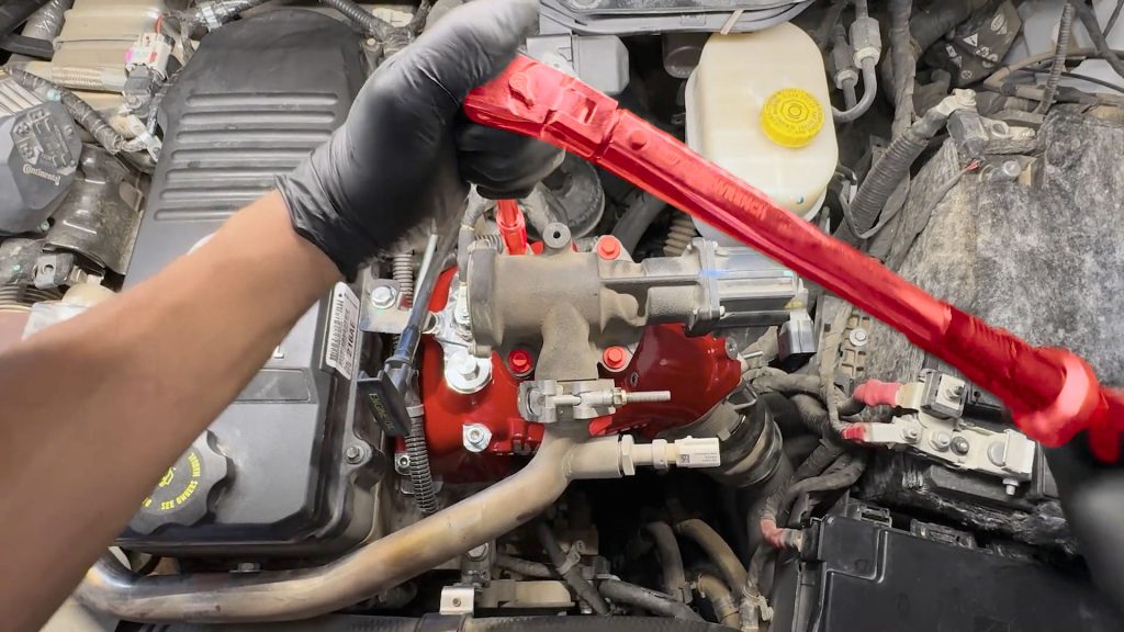
6. Use a telescopic magnet tool to install the short center bolt, and spin it a few threads.
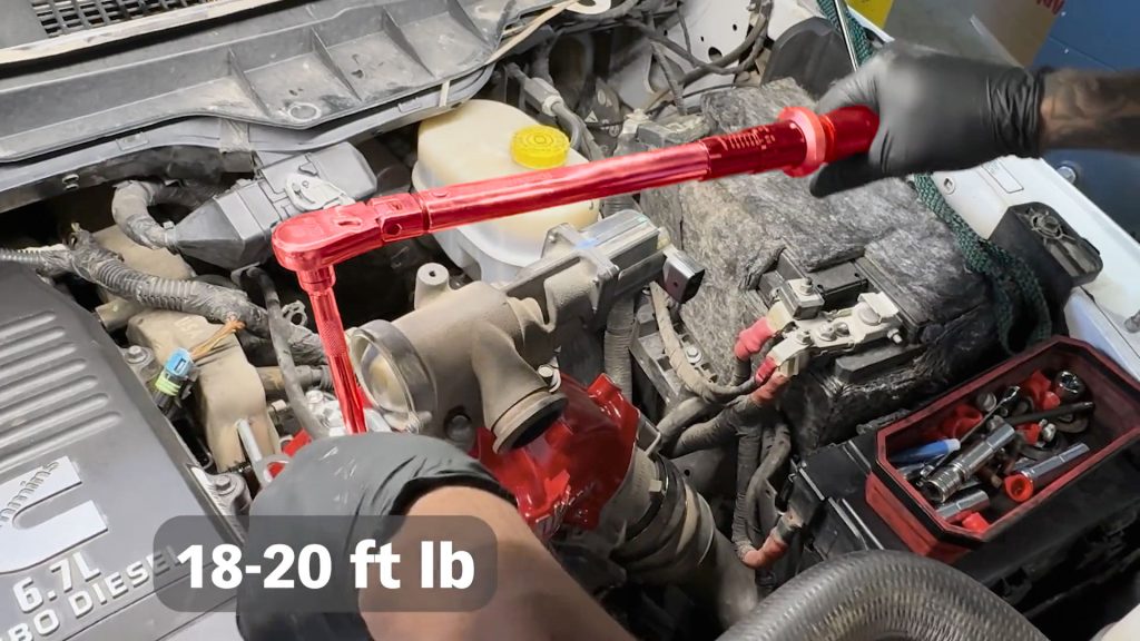
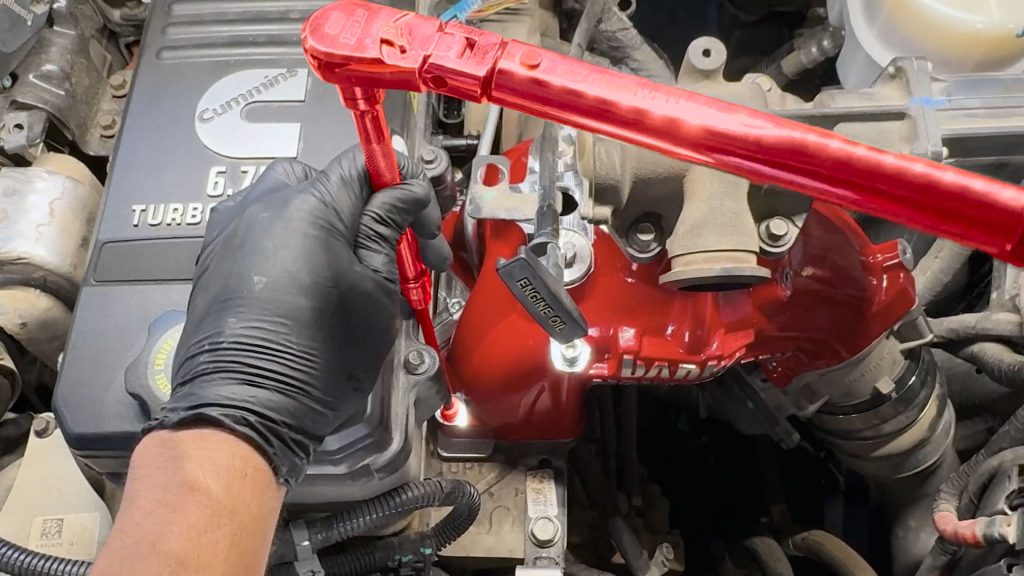
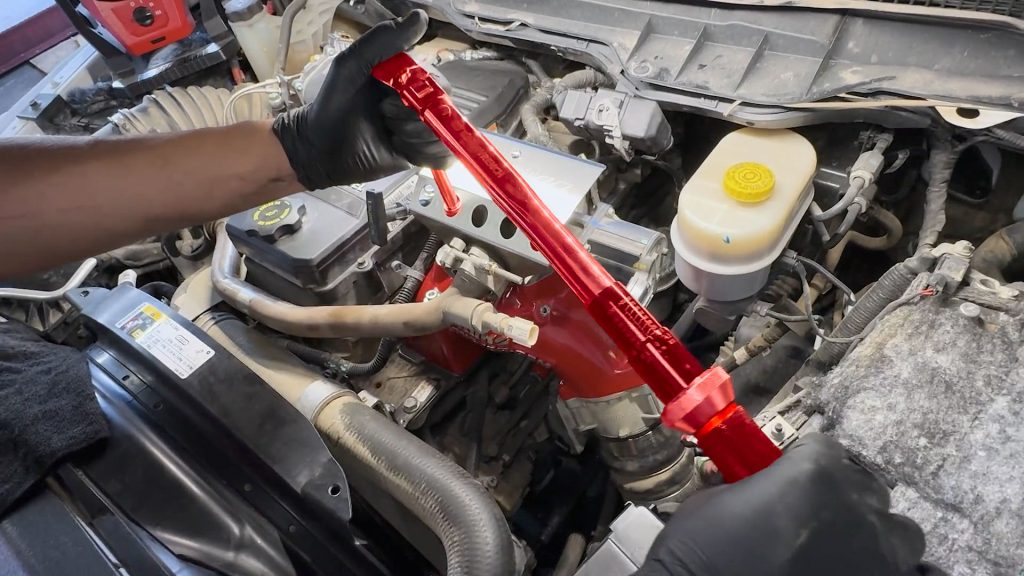
7. With the provided hex key extension, torque each bolt down to 18-20 ft-lbs
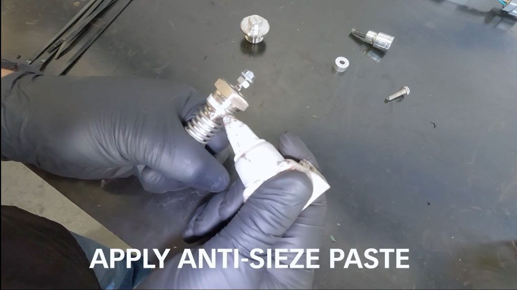
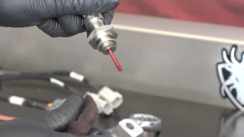
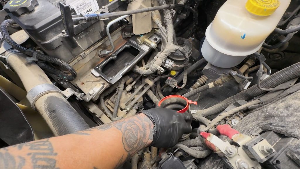
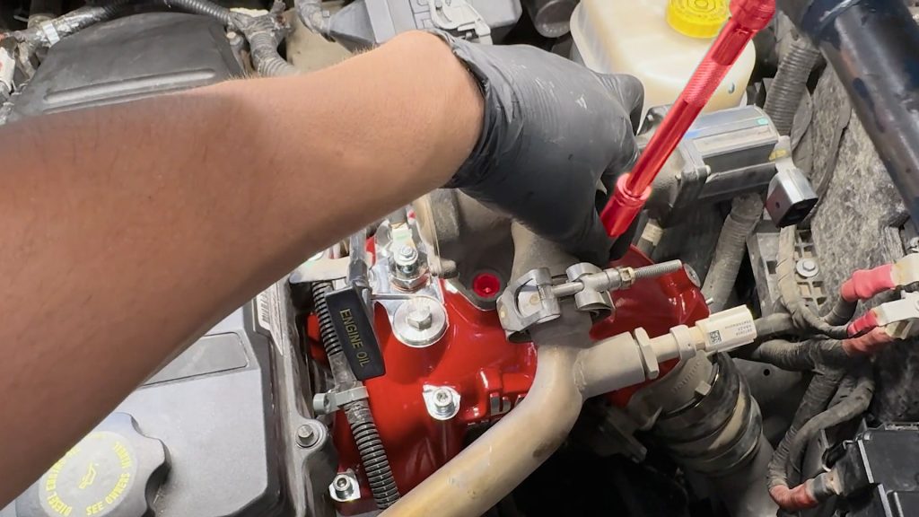
8. Apply some anti-seize compound to the threads of the coil heater.
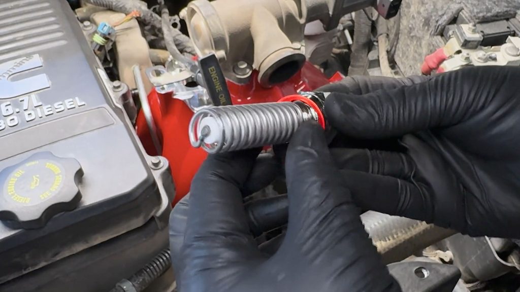
9. Slide the provided copper washer onto the coil heater.
10. Install the coil heater into the Monster-Ram, tighten it with a wrench till it’s snug, but don’t over-tighten it.

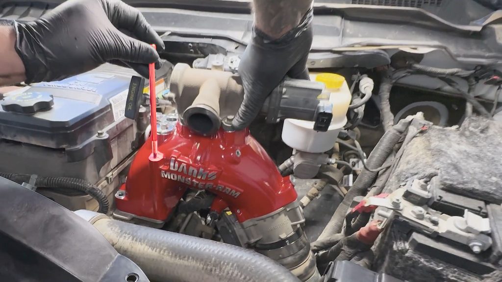
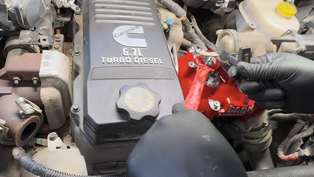
11. Put the dipstick relocation bracket and bolt together.
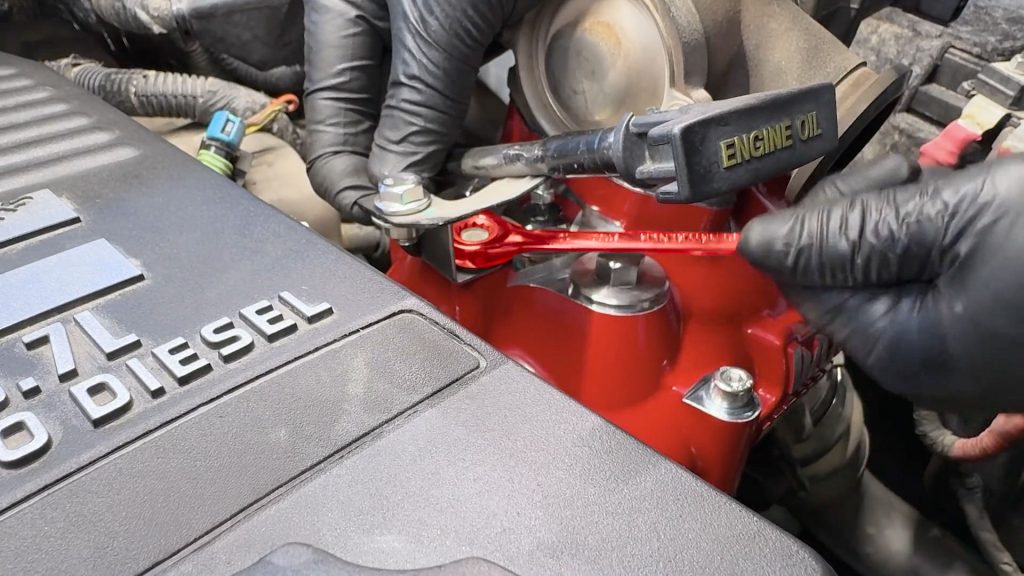
12. With a socket or wrench, tighten the bracket and dipstick tube.
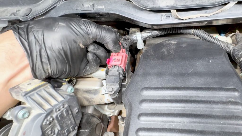
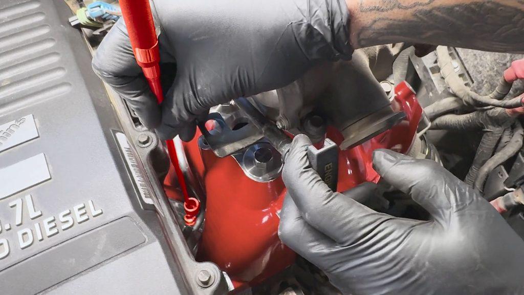
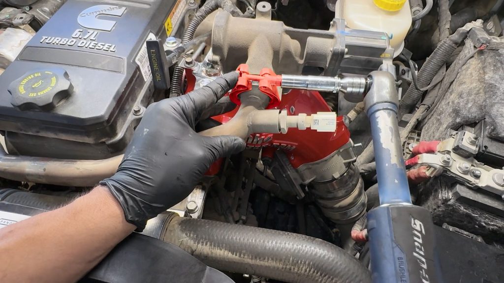
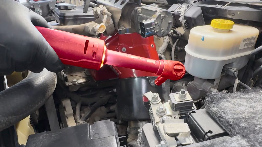
13. Reach around the back side of the Monster-Ram and plug the MAP sensor back into its harness.
14. Next, locate and plug in the throttle valve.
15. You’ll have to feel and blindly plug this one in. Once it’s connected, be sure to slide the pink locking tab in place.
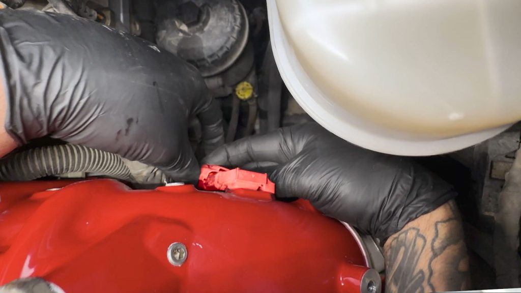
16. Slide the forward breather hose back onto the front barb from the cylinder head.
It can be a tight fit, so using a screwdriver to help wedge and push it on can help.
17. Plug in the front blue/green plug back into the valve cover.
18. Re-secure the harness wire loom to the dip stick tube with its cable tie.
19. With a deep socket, tighten the hose clamp on the boost tube.
The following step for the heater coil is critical.
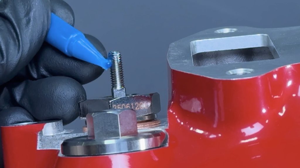
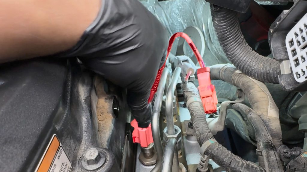
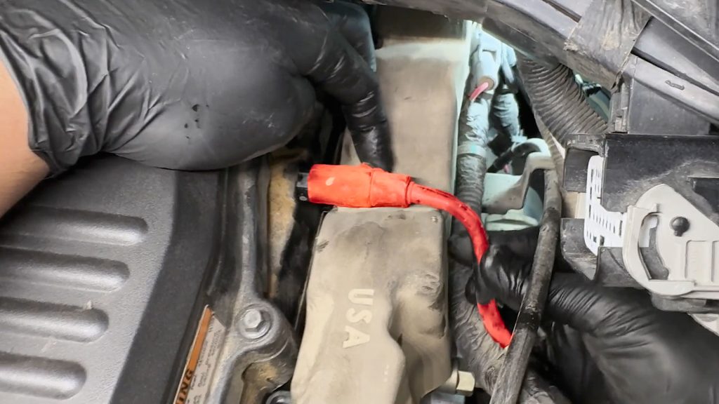
Heater Coil Prep
Remove the lower nut from the heater coil, and apply a drop of blue thread lock to the threads.
Replace the lower nut back onto the heater coil. Be sure the leave 1-2 threads visible under the nut.
You want to make sure the 12V heater cable does not come into contact with the rim of the heater coil.

Bend the end of the 12V power lead, and place it on top of the lower nut.

Sandwich the ring terminal between the two nuts by spinning the top nut down by hand.
The following step is critical. Failure to do so can break the internal insulated post free from the rest of the coil and damage the heating element.
When tightening the top nut of the heater coil, you must also place a crescent wrench on the lower nut so that it does not move.
You want to cinch the two together and sandwich the 12V power lead.
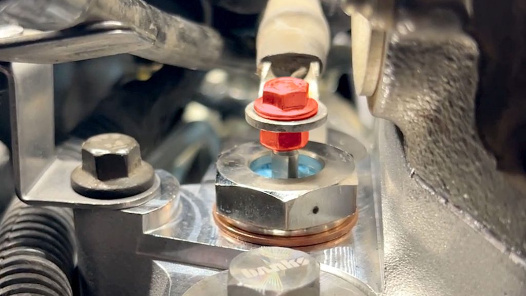
If done correctly, the 12V heater wire should look like this.
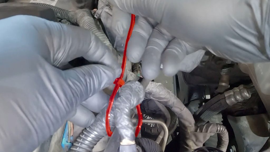
Secure any loose wire harnesses with some zip-ties.
14. EGR Crossover Tube Installation
1. Grab the EGR cross-over tube and the driver’s side clamp. Flip the clamp around so that the nut to tighten it is facing the driver’s side.
2. Replace the conical gasket on the driver’s side.
3. Replace the flat gasket on the passenger’s side.
4. Carefully holding both gaskets, bring the EGR crossover tube back down into the engine bay.
Keep constant pressure between the EGR cooler outlet and crossover tube to keep the gasket in place while you slide the v- band clamps into place.
5. Slide the driver-side clamp back onto the EGR valve. Start tightening it by hand then tighten with a deep socket.

6. With a deep socket, tighten the passenger side clamp.
7. Tighten down the rear 2 bolts to 18 ft lbs.
8. Remove the two front bolts from the EGR valve.
9. Swap the two bolts into the Banks EGR heat shield.
10. Bring the shield and two bolts back over the EGR valve.
11. Apply a drop of thread locker to the small screw that holds the rear of the EGR shield.
12. Grab the round aluminum spacer, place it under the heat shield, and tighten the screw through the hole on the top.
13. Torque the front two bolts to 18 ft-lbs.
14. Reinstall the two bolts that hold the throttle valve heat shield on.
15. Snug the two bolts down.
16. Connect the Banks-supplied EGR Valve and crossover tube temperature sensor extension harness.
17. Slide the pink locking tabs back to the locked position.
18. Reconnect both batteries.
19. Reconnect both batteries.
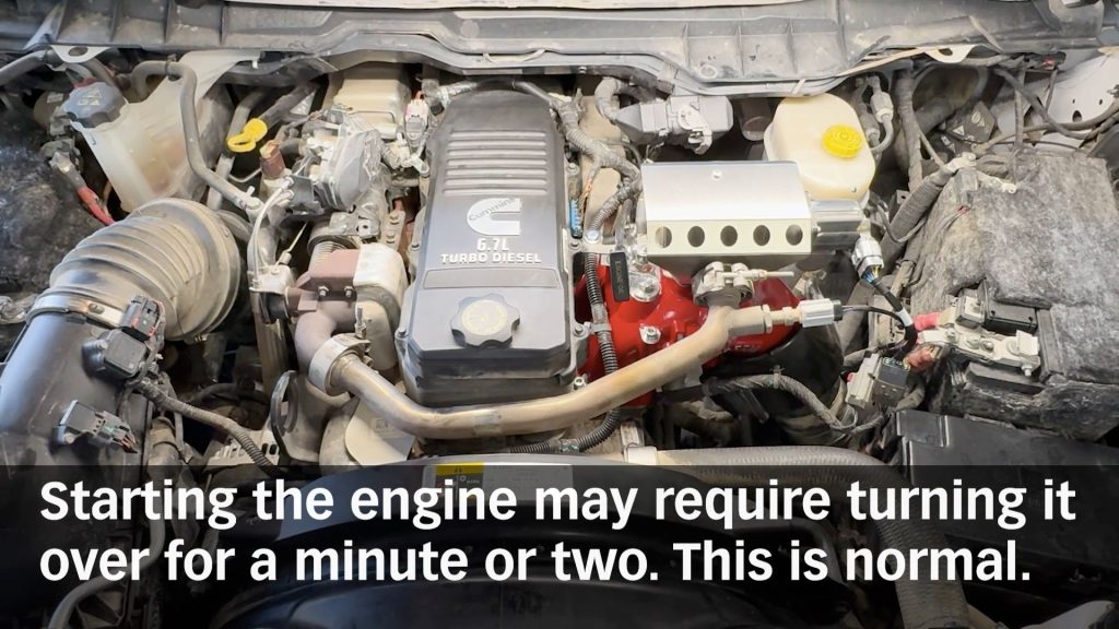
15. Check for leaks.
Check that all harnesses and components are free of moving parts. Check for any leaks while the engine is running.
Head out for a short test drive, then double-check for leaks one last time.

CARB EO Label
For smog check purposes, affix the CARB E.O. Label on a visible location under the hood. Banks recommends using the radiator shroud location.