


97661 Derringer Tuner for 2017-2019 GM 6.6L L5P Duramax
General Installation Practices
1. Before starting work, familiarize yourself with the installation procedure by reading all of the instructions.
2. The exploded views provide only general guidance. Refer to each step and section diagram in this manual for proper instruction.
3. Throughout this manual, the left side of the vehicle refers to the driver’s side and the right side to the passenger’s side.
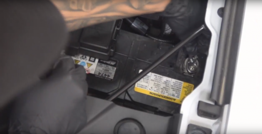
4. Disconnect the negative (ground) cable from the battery (or batteries, if there are more than one) before beginning work. The OEM battery clamp can be removed using a 10mm socket or wrench.
5. Route and tie wires and hoses a minimum of 6″ away from exhaust heat, moving parts, and sharp edges. Clearance of 8″ or more is recommended where possible.
6. During installation, keep the work area clean. Do not allow anything to be dropped into the intake, exhaust, or lubrication system components while performing the installation, as foreign objects will cause immediate engine damage upon start-up.
CAUTION! Do not use floor jacks to support the vehicle while working under it. Do not raise the vehicle onto concrete blocks, masonry, or any other item not intended specifically for this use.
Disclaimers
THIS IS A HIGH-PERFORMANCE PRODUCT. USE AT YOUR OWN RISK. Do not use this product until you have carefully read the following agreement.
This sets forth the terms and conditions for the use of this product. The installation of this product indicates that the BUYER has read and understands this agreement and accepts its terms and conditions.
Disclaimer of Liability
Gale Banks Engineering Inc. and its distributors, employees, and dealers (hereafter “SELLER”) shall in no way be responsible for the product’s proper use and service. The BUYER hereby waives all liability claims.
The BUYER acknowledges that he/she is not relying on the SELLER’s skill or judgment to select or furnish goods suitable for any particular purpose and that there are no liabilities which extended beyond the description on the face hereof and the BUYER hereby waives all remedies or liabilities, expressed or implied, arising by law or otherwise, (including without any obligations of the SELLER with respect to fitness, merchantability, and consequential damages) whether or not occasioned by the SELLER’s negligence. The BUYER is responsible to fully understand the capability and limitations of his/her vehicle according to manufacturer specifications and agrees to hold the SELLER harmless from any damage resulting from the failure to adhere to such specifications.
The SELLER disclaims any warranty and expressly disclaims any liability for personal injury or damages. The BUYER acknowledges and agrees that the disclaimer of any liability for personal injury is a material term for this agreement and the BUYER agrees to indemnify the SELLER and to hold the SELLER harmless from any claim related to the item of the equipment purchased. Under no circumstances will the SELLER be liable for any damages or expenses by reason of the use or sale of any such equipment.
The BUYER is responsible to obey all applicable federal, state, and local laws, statutes, and ordinances when operating his/her vehicle, and the BUYER agrees to hold SELLER harmless from any violation thereof.
The SELLER assumes no liability regarding the improper installation or misapplication of its products. It is the installer’s responsibility to check for proper installation and if in doubt, contact the manufacturer.
The BUYER is solely responsible for all warranty issues from the automotive manufacturer.
Limitation of Warranty
Gale Banks Engineering Inc. (hereafter “SELLER”), gives Limited Warranty as to description, quality, merchantability, fitness for any particular purpose, productiveness, or any other matter of SELLER’s product sold herewith. The SELLER shall be in no way responsible for the product’s open use and service and the BUYER hereby waives all rights except those expressly written herein. This Warranty shall not be extended or varied except by written instrument signed by SELLER and BUYER.
Please see the enclosed warranty information card, or go to our warranty page for information regarding your product. All products that are in question of Warranty must be returned shipping prepaid to the SELLER and must be accompanied by a dated proof of purchase receipt. All Warranty claims are subject to approval by Gale Banks Engineering Inc.
Under no circumstance shall the SELLER be liable for any labor charged or travel time incurred in diagnosis for defects, removal, or reinstallation of this product, or any other contingent expense.
Under no circumstances will the SELLER be liable for any damage or expenses incurred by reason of the use or sale of any such equipment.
IN THE EVENT THAT THE BUYER DOES NOT AGREE WITH THIS AGREEMENT:
The BUYER may promptly return this product, in a new and unused condition, with a dated proof-of-purchase, to the place-of-purchase within thirty (30) days from date-of-purchase for a full refund, less shipping and/or restocking fee.
The installation of this product indicates that the BUYER has read and understands this agreement and accepts its terms and conditions.
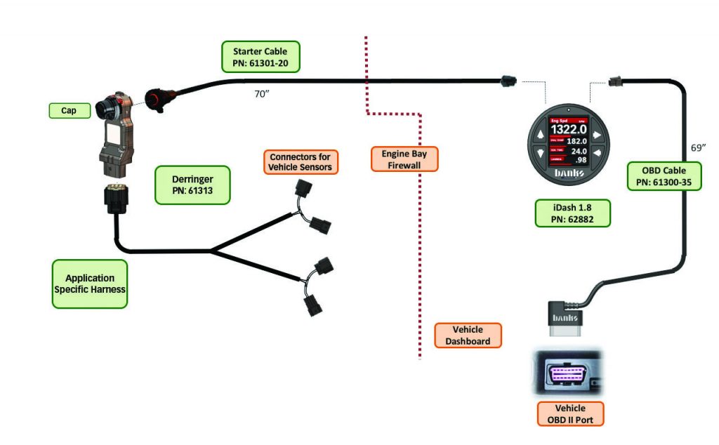
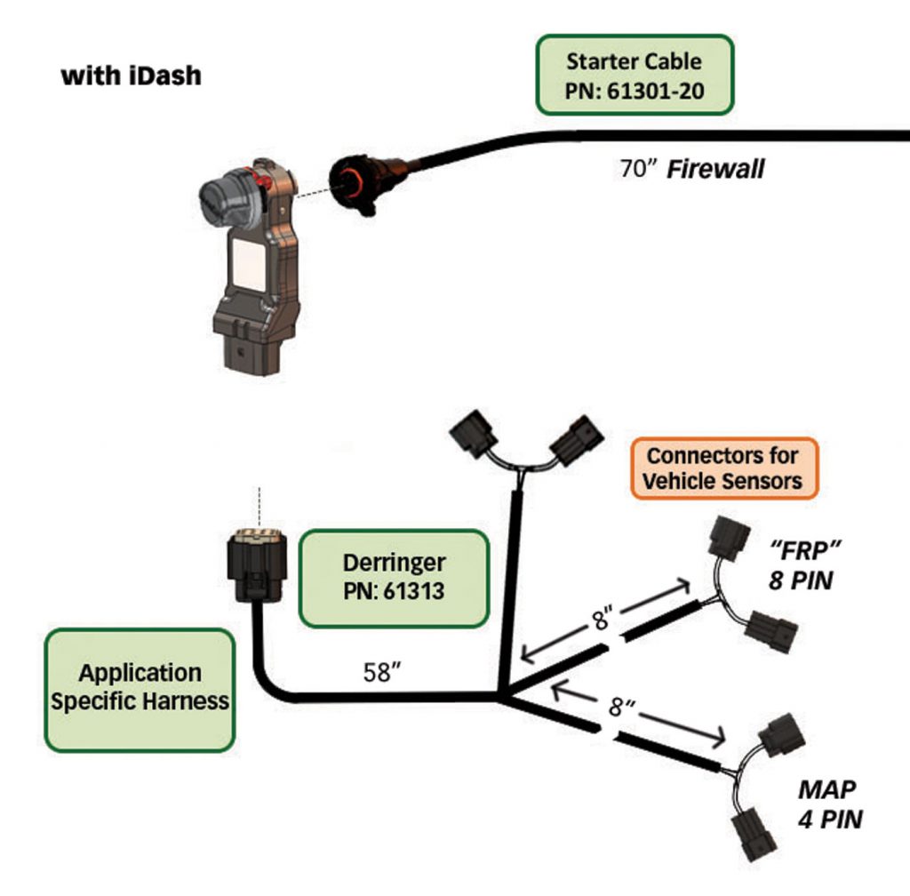
Section 1.0 Wiring Diagram
iDash 1.8″ Configuration
Derringer Sensor Harness Installation
WARNING:
Ensure that the engine bay is cool and remove the keys from the ignition. Disconnect the battery GROUND (-) cables (Figure 1.2-4). Secure the cables so that they do not come in contact with the battery posts during the installation.
NOTE:
If the ECU is powered on when the sensors are disconnected, your vehicle will show diagnostic trouble codes.
Vehicle Specific Instruction 1.4.2:
2017-2019 GM 6.6L L5P
Sensor Locations/Connection Instructions
1. Before locating and disconnecting anything, ensure you are using the designated GM L5P Derringer harness by identifying the sensor label.
NOTE: GM L5P Derringer harness connects to Fuel Rail Pressure (FRP) and Temp/Manifold Absolute Pressure (TMAP) sensors. Pull only on the connector, do not pull on the wires. (No tools required.)
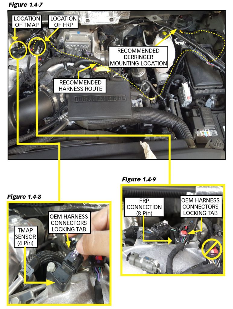
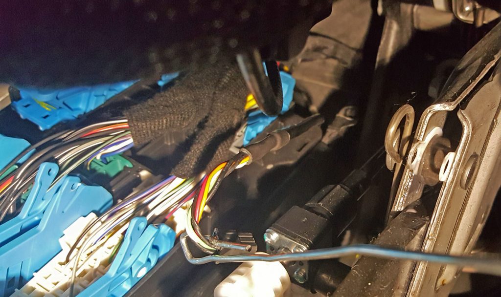
2. Locate the TMAP and FRP connectors on the GM L5P engine bay. See Figure 1.4-7.
3. On the top of the L5P engine you will find a TMAP sensor mounted on the manifold. Disconnect the 4 pin sensor by pulling the gray OEM harness connectors’ locking tab and sliding the OEM harness away from the TMAP sensor. See Figure 1.4-8.
NOTE: There are two similar OEM connectors next to the previously mentioned TMAP sensor. The following FRP connection that will be utilized is the 8 pin connector CLOSEST to the previous TMAP sensor mentioned. See Figure 1.4-9.
4. Right next to the TMAP sensor is the OEM FRP connection (8 Pin) that will be used to connect the FRP sensor. It can be reached without disconnecting or removing other components. To disconnect the OEM harness from the
FRP connection, pull the OEM harness connector red locking tab and slide the OEM harness away from the FRP connection. See Figure 1.4-9.
5. Plug the Derringer harness connectors labeled MAP between the MAP sensor and MAP OEM harness. Next plug the Derringer harness connectors labeled FRP between the FRP connection and the FRP OEM harness.
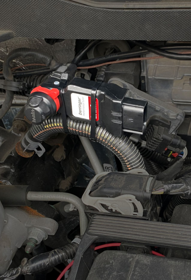
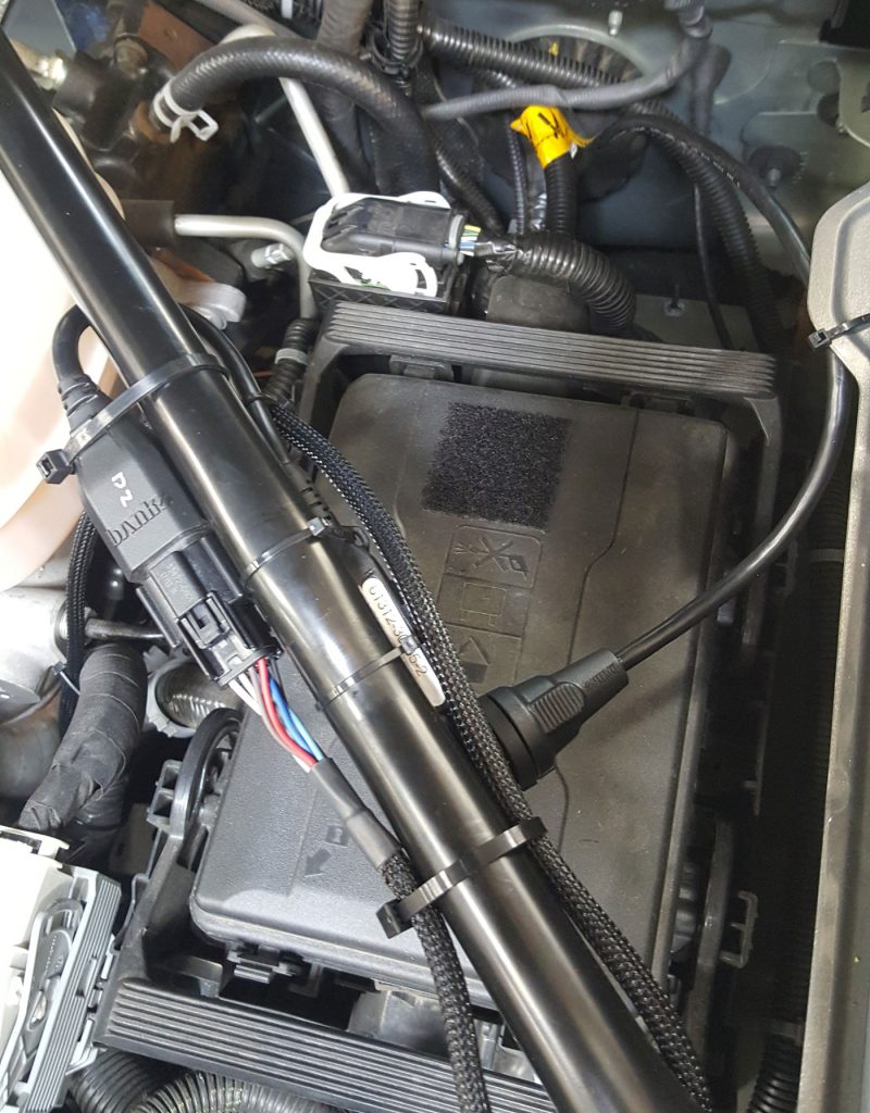
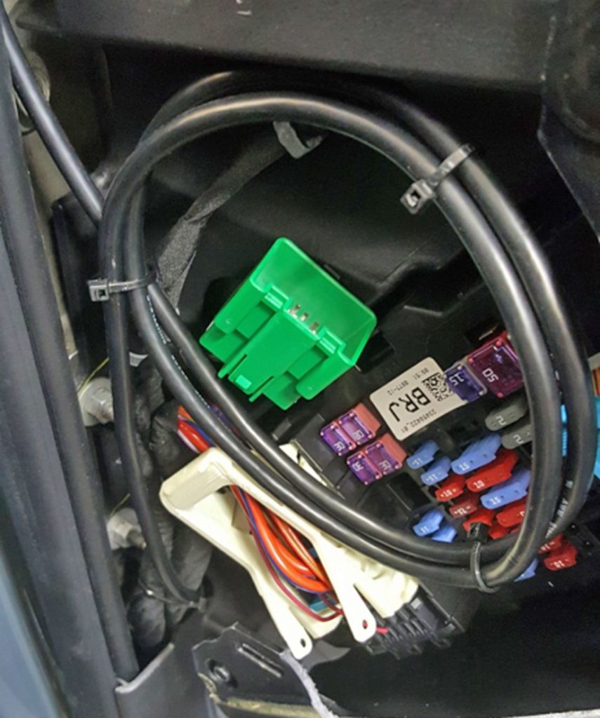
6. It is suggested to route the rest of the Derringer harness along the OEM harness route. Connect the Derringer module to the Derringer sensor harness. Locate a place to secure the Derringer module near or along the fender, then zip-tie it in place. See Figure 1.4-7.
NOTE: The pictured mounting location of the Derringer Tuner is optional. It is best to mount close to the firewall and route the harness along the OEM harness. See Figure 1.4-7.
Derringer Tuner Installation
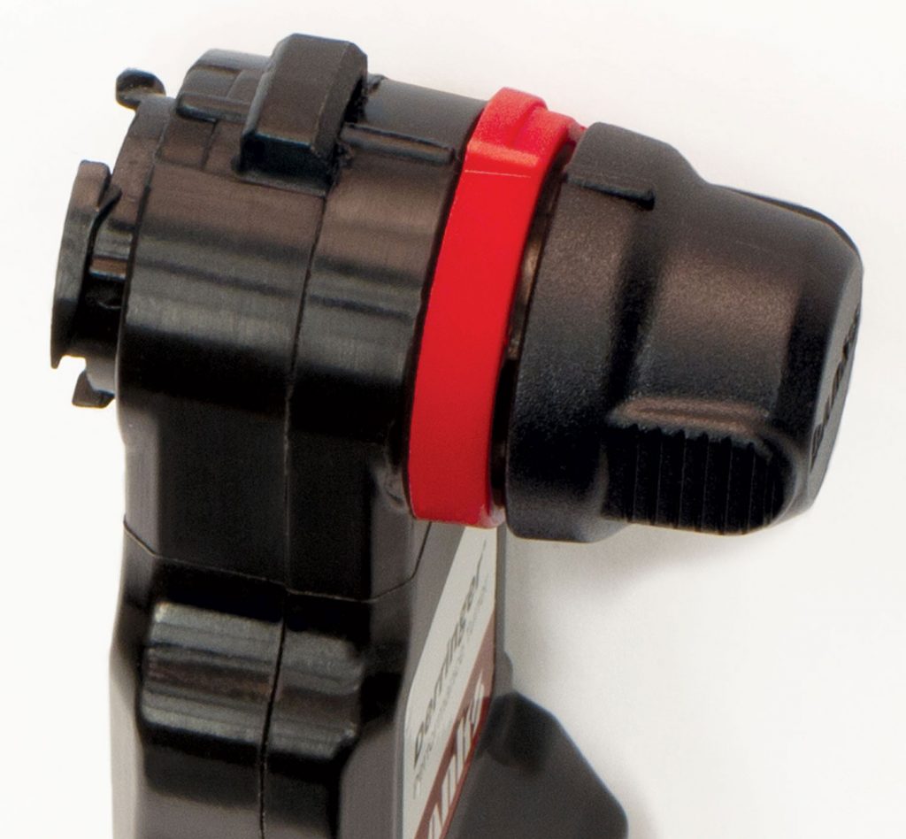
1. Connect the Derringer Module to the Derringer Sensor Harness and the Started Cable. See Figure 1.3-1.
2. Rotate the locking ring towards the 12 o’clock position then connect the mating ends together ensuring proper alignment using the 12 o’clock marks. See Figure 1.3-2
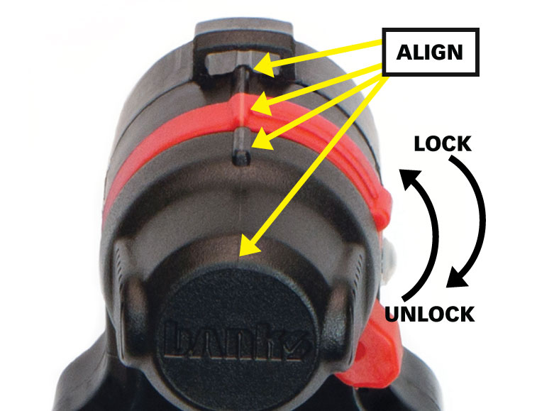
3. Then rotate the locking ring towards the lock icon until you feel a click. See Figure 1.3-3.
4. Locate a place to secure the Derringer module near or along the fender, then zip-tie it in place. Ensure the LED indicator is viewable in selected location. Secure any extra cable of the Derringer Sensor Harness without pinching the harness.
NOTE: The pictured mounting location of the Derringer tuner is optional. It is best to mount close to the firewall and route the harness along the OEM harness.
5. Check all connectors for proper installation, then connect the battery terminal(s).
Starter Cable Firewall Installation
1. Locate any possible passage for wire routing, inspect the firewall from under the dash (in the footwell) and from under the hood.
2. Route the Starter Cable through the firewall using the OEM wire harness grommet.
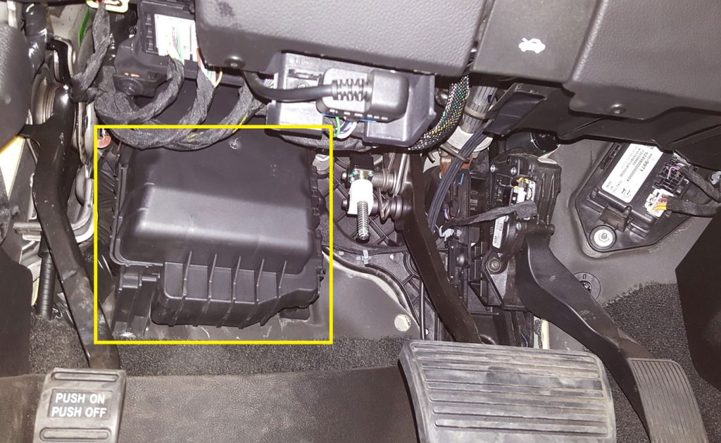
A. Locate the OEM wire harness grommet. See Figure 1.4-1.
B. From the engine bay side, insert a large Phillips screwdriver to move grommet edge aside. See Figure 1.4-2.
C. Confirm the screwdriver has penetrated into the cab by checking under the dash. See Figure 1.4-3.
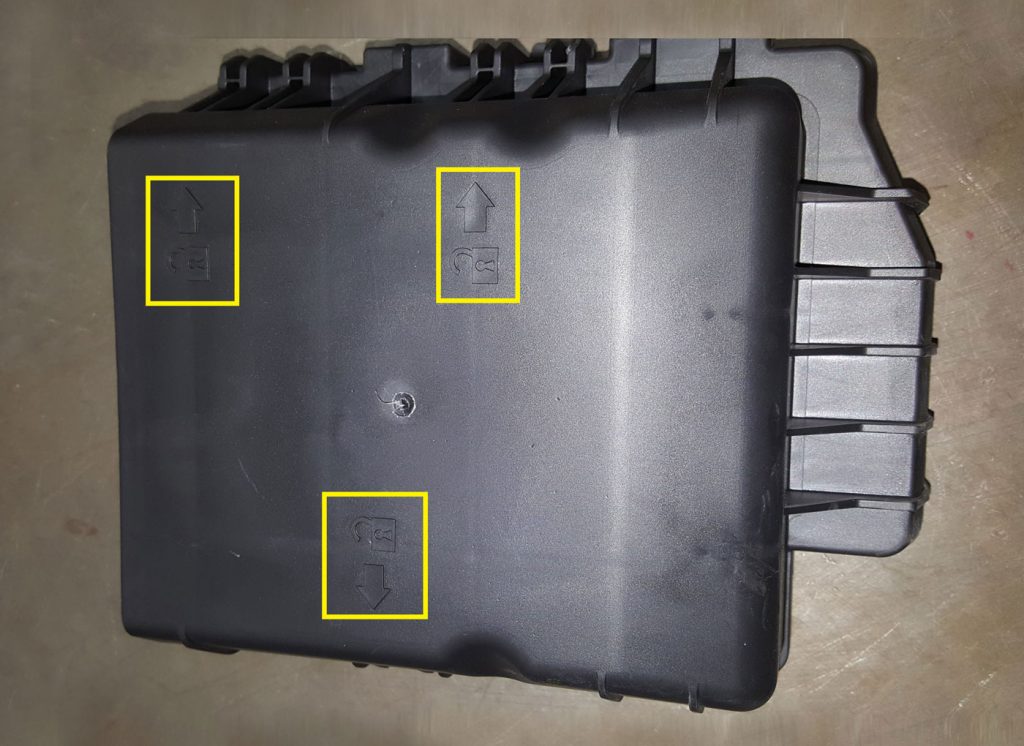
D. Remove the plastic cover or easier access to the grommet under the dash. Unclip the sides that are indicated by the lock icon. See Figure 1.4-3, 1.4-4.
NOTE: Pushing the screwdriver through at an angle helps push the grommet lip on the other side of the firewall. Take care to not pierce the grommet.
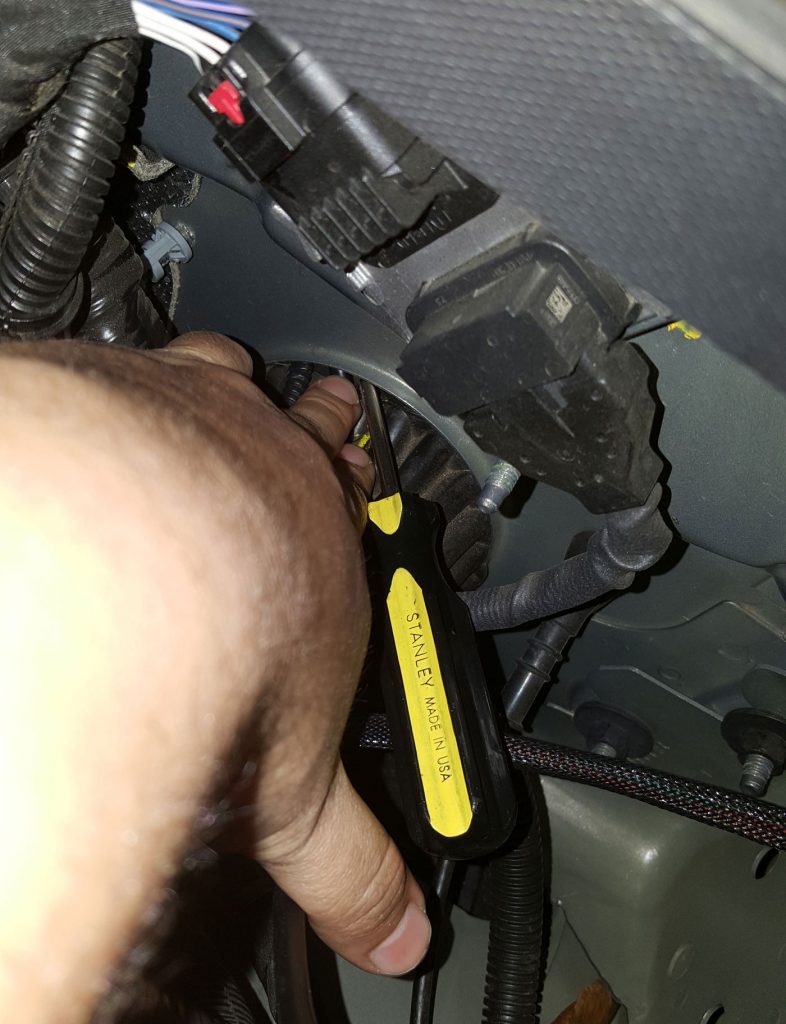
NOTE: Unclip the left side first. See Figure 1.4-3.
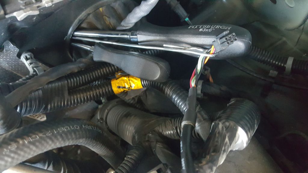
E. Take a wire coat hanger (or any other wire) and create a hook to pull the starter cable with. See Figure 1.4-5.
F. On the engine bay side push the coat hanger with the Starter Cable terminal through the grommet by hand.
G. Pull the wire coat hanger from inside the cab until the Starter Cable can be reached. See Figure 1.4-6.
H. Ensure there is enough of the Starter Cable length in the cab (~ 4ft) to route to the iDash 1.8 or Switch.
In-Cab Installation
Required Tools & Materials
• Zip-ties (4″ or longer)
• Cutting tool (i.e. Diagonal Cutters)
• Large standard screwdriver
• Power drill*
- Plug the OBD-II Cable into the OBD-II port located under the dash. See Figure 1.5-1.
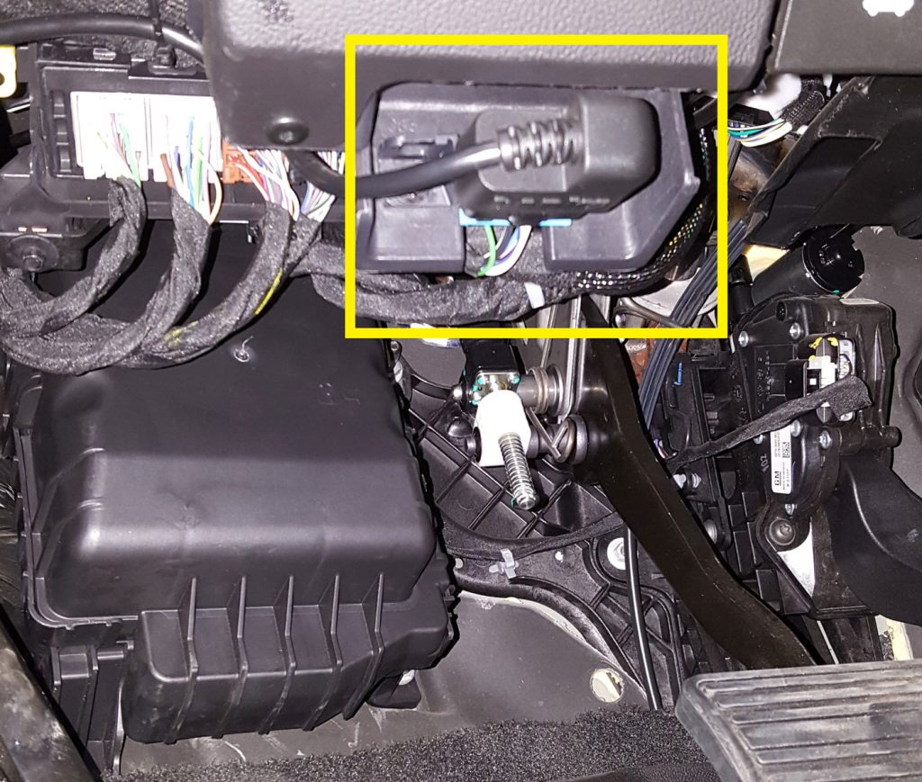
2. Route the Starter Cable and OBD-II Cable to the dash.
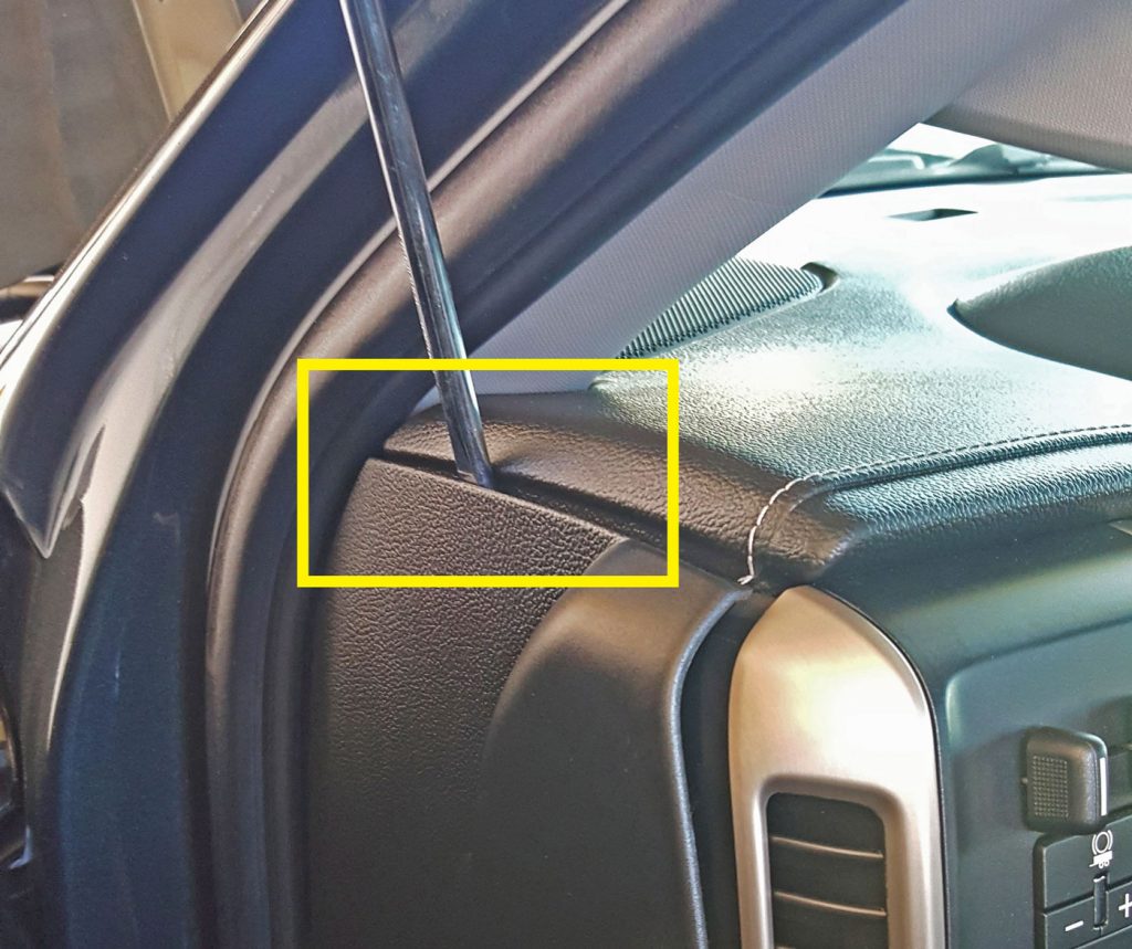
3. Remove the side dash cover to store any excess wire.
See Figure 1.5-2, 1.5-3.
For iDash 1.8″ Configuration
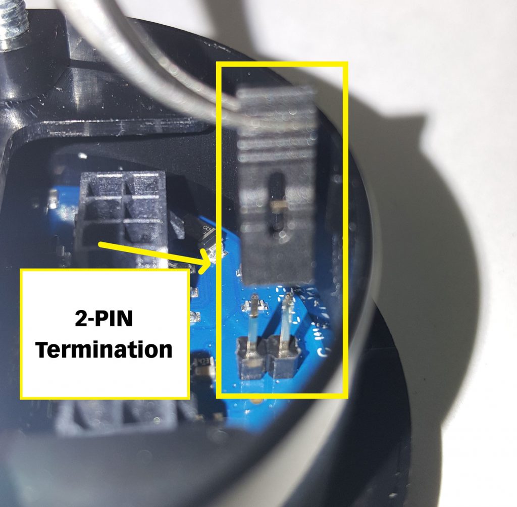
- Connect the Starter Cable to the iDash 6-Pin Port. See Figure 1.5-4.
2. Check for the pre-installed Jumper Block to the iDash 2-Pin termination.
See Figure 1.5-5.
Please note: If installing multiple iDash 1.8 continue to Step 3, if not you are finished. Skip to page 21.
3. Connect the Y-Cable to the 6-pin port of the first and second iDash 1.8 (without the In-Cab Terminator). See Figure 1.5-6
A. Connect the starter cable to the Y-cable. See Figure 1.5-6, Step 3C.
B. Remove extra jumper black from the secondary iDash 2-Pin terminations. See Figure 1.5-5.
Note: Only one jumper block terminator is required.
4. Install the iDash 1.8 in an A-pillar mount or a suction cup windshield-mount gauge-pod.
Section 2.0
Derringer Tuner Operation
Setting Desired Power Level:
The Derringer is equipped with multiple power levels. You can set the desired power level while the engine is running but it is recommended that you do not switch the power level under high load applications.
iDash 1.8 Configuration:
When the Derringer is connected to an iDash 1.8, there are a total of six power levels (level 6, 5, 4, 3, 2, and stock). The power level can be changed by pressing the UP and DOWN buttons at any time. See iDash user guide for details on iDash setup. If you have the derringer layout loaded, you will see the power level change at the bottom left corner (See Figure 2-1). If you have any other layout loaded, a message box will pop up to notify you of the power level change.
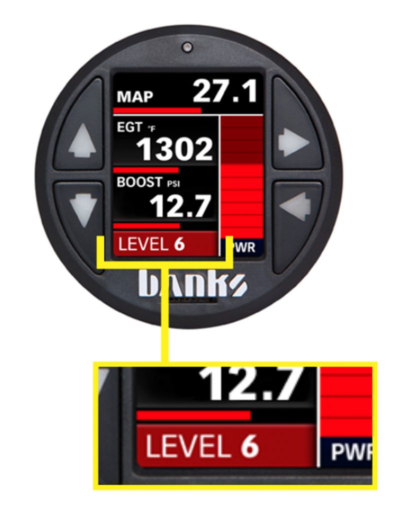
Sport Mode / Level 6
This mode is to be used when peak engine performance is required. This mode has been optimized for maximum power output along with improved turbo response by tuning fuel delivery and boost.
Plus Mode / Level 3
The plus calibration is designed for use in everyday driving. This power level adds a noticeable punch under high load acceleration by improving turbo response and power. Power in this mode can be sustained for a prolonged duration.
Stock Mode
Stock mode turns OFF your Derringer tuner. Throttle response and power return to stock levels.
Banks ActiveSafety®
Anytime aftermarket electronics are introduced to your vehicle, it is important to know that they are not going to cause damage. Banks builds in a suite of ActiveSafety features to safeguard your vehicle:
• Software that monitors and diagnoses itself to ensure proper function.
• Self-monitoring hardware that provides automatic bypass should something malfunction.
The Derringer Tuner module monitors multiple parameters and adjusts its output controls to protect the driveline. The Derringer Tuner monitors engine coolant temperature (ECT) and will limit the additional power that it provides anytime the ECT is outside of optimal operating range to protect the engine.
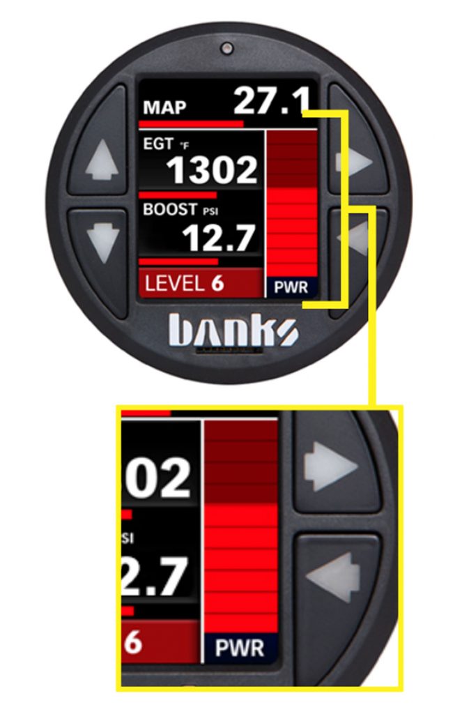
Power Added (%):
If connected to an iDash 1.8 while displaying the “Derringer” layout, the vertical bar graph on the right-hand side represents, in real-time, how much power the Derringer is adding (See Figure 2-2). In Stock Mode, there will be no change to the bar graph and in Sport Mode/Level 6 the bar graph will reach 100% under proper operating conditions. Percent power added is affected by safety features such as Engine Coolant Temperature, Exhaust Gas Temperature, Regen., and various transmission parameters, so it might not always fully reach 100%. The “Power Added” data can also be displayed on ANY layout as a numeric value by selecting it from the “Derringer” category of parameters.
Automatic Transmission Learning:
6.6L Chevy Duramax Trucks equipped with the Allison 1000 6-speed automatic transmission use an adaptive shift control logic. After initial installation of the Derringer Tuner, wide open throttle shifts may feel soft when switching to higher power levels. Also, when switching to lower power levels, shifting may feel harsher. Continued use at a single power level will provide more consistent shifting performance.
- To accelerate the learning process perform the following sequence at a location where it is safe to accelerate without exceeding the posted speed limit.
2. Adjust the Derringer Tuner to Plus Mode/Level 3 power setting.
3. Drive your vehicle for 5-10 miles, ensuring a complete shift cycle through each gear (The transmission shift learning process requires 15-30 complete shift cycles to learn a new shift program).
4. Increase power level to Sport Mode/Level 6 and repeat Step 3.
Section 3.0
Troubleshooting
Normal Operation
Your Derringer Tuner has a built-in, self-diagnostic system. The status of the Derringer system is communicated via the LED on the module. When the Derringer Tuner is functioning properly the LED will flash green with the engine cold and solid green when warm.
Derringer Not Powered
When the LED is not illuminated, the Derringer Tuner is not powered on. If the ignition is on and the LED is not illuminated, check the TMAP connections on the vehicle and ensure they are fully engaged.
LED Error Code
When faults are detected, the Derringer Tuner will flash a diagnostic code. These diagnostic codes are comprised of two digits. Each digit is expressed by the flashing red LED.
A code can be determined by counting the number of red flashes displayed before the LED flashes green for the first digit and the number of red flashes after the LED flashes green for the second digit. After the diagnostic code is displayed, additional codes will be displayed in sequence, separated by four seconds with the LED off. Once all codes are displayed the Derringer will begin sending the codes again. Once you have written down all diagnostic codes being displayed, consult the following tables for a description of the code along with the action to be taken.
iDash Display Error Code
If error code “D-ERR!” appears on the iDash, refer to the following to display the code and description:
Settings > Diagnostics > Select the module that is giving the error
61312-51 Derringer Tuner (GM L5P application)
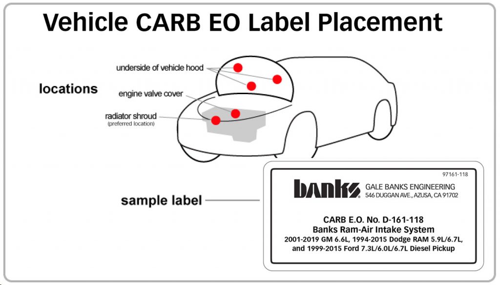
CARB EO Label
Please use the following CARB-approved emissions label and EO label location guidelines. We generally use the radiator shroud location.
Congratulations! You’ve installed your Banks Derringer Tuner. Enjoy!