
97654 iDash 1.8 DataMonster and Super Gauge: Section 12: Settings
INSTALL INSTRUCTIONS
Part #s
66560, 66561, 66562, 66563, 61410, 66760
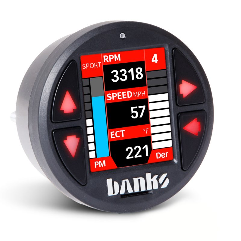
iDash 1.8 DataMonster® & Super Gauge Stand alone instrument for ALL 2008+ OBDII CAN bus vehicles
Please read through the following instructions thoroughly before starting your installation. If you have any questions please visit our Support Page.
Section 12: Settings
The iDash features many customizable settings allowing for personalization. Most user-configurable settings can be adjusted in the “Settings” menu. This menu allows you to set up the number of gauges to display.
12.1 Layout
- Go to “MENU” and select “Settings” and then select “Layout.” NOTE: The “Layout” menu can also be accessed in the “Settings” menu.
- Select the desired layout and you will automatically be returned to the “Gauge Screen.“
12.2 Brightness
In this menu, customizing the brightness of your iDash buttons and LCD screen is made easy. All iDash’s come with an “Auto-Dimming” feature that senses the ambient light conditions and adjusts the brightness of the buttons and
LCD screen
“Auto-Dimming” can be configured to limit the range of brightness and its sensitivity to changes in ambient conditions. This feature can also be deactivated.
NOTE: Brightness settings saved will note reset when switching between “Auto-Dimming” disabled and enabled.
To enable/disable “Auto-Dimming“:
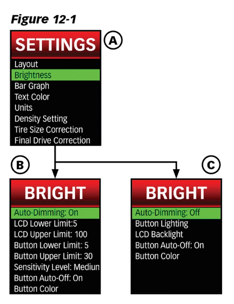
- Select “Settings” from the main “MENU.” Select “Brightness.” Figure 12-1, A.
- Select “Auto-Dimming” to toggle ON or OFF. See Figure 12-1, B & C. NOTE: The “Brightness” menu will change depending on the status of “Auto-Dimming.”
12.2-2 Sensitivity Level
Note: The subsequent settings are only available when “Auto-Dimming” in “ON.” Figure 12-1, B.
This controls how sensitive the iDash device is to changes in ambient light.
If the sensitivity level is high, the display brightness will change often and at low sensitivity, it will change slowly.
To adjust auto-dimming sensitivity:
- Select “Settings” from the main “MENU.” Then select “Brightness” and after that, “Sensitivity Level.”
- Adjust the sensitivity level (“Low,” “Medium,” or “High“) and select the desired setting to save.
12.2-3 LCD Brightness Upper/Lower Limit
The brightness of the display can be limited to a defined low brightness setting and high brightness setting for Auto-Dimming to adjust between these limits.
- Select “Settings” and then “Brightness” and finally, “LCD Lower Limit” or “LCD Upper Limit.“
- Scroll UP or DOWN to adjust the LCD screen brightness. The brightness value will be displayed in percentages, 0-100%.
- Select the desired value to save the setting.
12.2-4 Button Brightness Upper/Lower Limit
- Select “Settings” and then “Brightness” and finally, “Button Lower Limit” or “Button Upper Limit.”
- Scroll up and down to adjust the brightness and then select the desired value to save the setting.
12.2-5 LCD Backlight
- Select “Settings” and then “Brightness” and finally, “Button Lower Limit” or “LCD Backlight.” See Figure 12-1, C.
- Scroll up or down to adjust the LCD brightness and select the desired value to save the setting.
12.2-6 Button Lighting
NOTE: Only available when “Auto-Dimming” is “OFF.” See Figure 12-1, C.
- Select “Settings” and then “Brightness” and finally, “Button Lighting.”
- Scroll up and down to adjust the brightness and select the desired value to save the setting.
12.2-7 Button Auto-Off
This feature turns off the button LED’s after ~10 seconds of inactivity on the “Gauge Screen.” This feature can be disabled to have the button LED’s always on.
- Select “Settings” and then “Brightness” and finally, “Button Auto-Off” to toggle on or off. Figure 12-1, B or C.
- Return to the Gauge Screen when finished.
12.2-8 Button Color
- Select “Settings” and then “Brightness” and, “Button Color.”
- Scroll up or down through the color selection screen and press “Yes” to select a color.
12.3 Bar Graph
For layouts “2 Gauge” to “5 Square Light” there is a bar graph representation of the parameter values on the Gauge Screen.
In the “Bar Graph” menu, the bar graphs can be disabled/enabled, have the color changed, and adjust the min/max values represented.
Enable/Disable Bar Graphs
When bar graphs are disabled, all graphs are removed from the display except for the bar graph in “Field 1” in the density layout. The density bar graph will be shown at 100%.
Note: This setting will not affect the Derringer power output graph.
- Select “Settings” from the “Menu” and then “Bar Graph.”
- Select “Bar Graph: Enable” or “Bar Graph: Disable” to turn the bar graphs on or off.
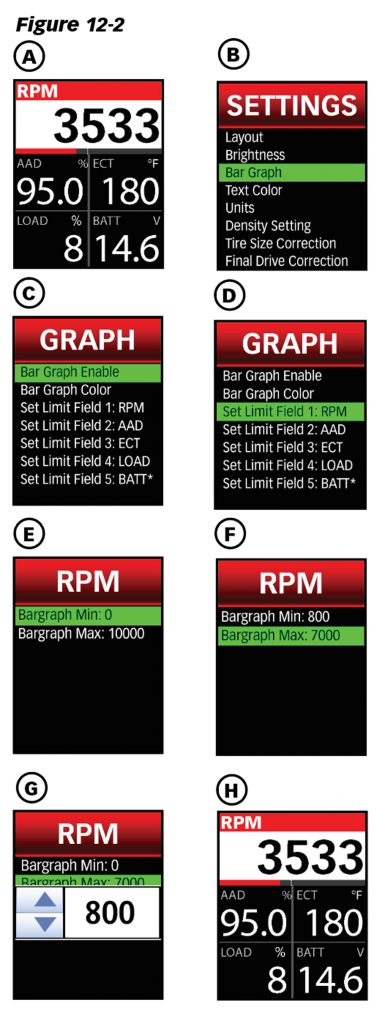
- Return to Gauge Screen when finished. Figure 12-2, C.
Bar Graph Color
The bar graphs can be customized using the 23 available colors.
- Select “Settings” from the main menu and then select “Bar Graph.” See Figure 12-2, B.
- Select “Bar Graph Color” (See Figure 12-2, C) to enter the color selection screen.
Bar Graph Limits
Each bar graph can have the maximum and minimum value displayed changed.
The bar graph limit settings are not saved when the parameter is removed from the Gauge Screen, so the setting will have to be reconfigured every time a parameter is changed.
Note: The density bar graph does not support configurable limits, but can be scaled.
To set the min and max values displayed on the bar graphs:
- Select “Settings” from the main “MENU” and then “Bar Graph.”
- Select a parameter “Set Limit Field #:” to adjust the bar graph. Figure 12-2, D.
- Select “Bargraph Min:” or “Bargraph Max:” See figure 12-2, E & F.
- Scroll Up or Down through the values and then sekect the value to save the setting.
- Return to the “Bar Graph” menu and repeat this process to adjust any other parameter listed.
Text Color
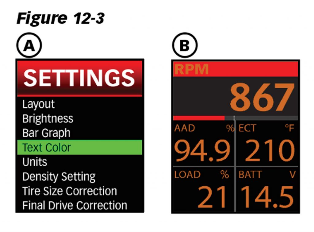
Customize the look of your gauge display by selecting from one of 23 different text colors. All text in the menu and Gauge Screen will show the color selected.
Text on alerts, the shift light, and notification banners will remain unchanged by this setting.
- Select “Settings“from the main “MENU.” Select “Text Color” to enter the color selection screen. Figure 12-3, A
- Scroll up and down through the color selection screen and press “Yes” to select a color.
- Return to the Gauge Screen when finished.
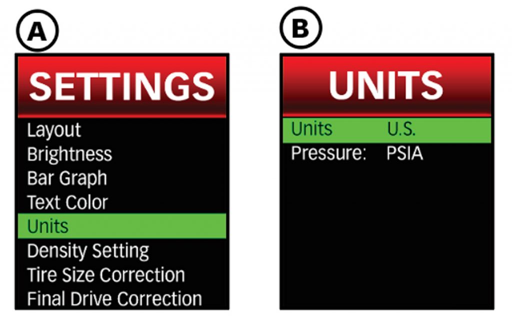
12.5 Units
Choose to display your preferred units for parameter values.
US/Metric
This setting allows you to select whether to view parameter information in U.S. or Metric units.
Note: This setting does not affect pressure parameters. The units for pressure parameters are set using the “Pressure” units setting.
- Select “Settings” from the main “MENU.” Select “Units” in the “Settings” menu.
- Select “Pressure:” to switch between “PSIA“, “BAR” or “KPA.” Figure 12-4, B.
Tire Size Correction
This feature will allow you to correct the vehicle speed displayed on the iDash when enabled. So when you change the tire size of your vehicle, you can still reference the correct vehicle speed.
To correct vehicle speed for a tire size change:
- Select “Settings” from the main “MENU.” Then select “Tire Size Correction.”
- Select “Speed Correction:” to “Enable” or “Disable” the speed correction feature.
- Select “Stock Tire:” to then input the vehicle’s stock tire size information.
- Select “Width” and scroll up and down to adjust the value.
- Repeat the previous steps for “Aspect” ratio and “Wheel Diameter.”
- Select “Current Tire” to then input the vehicle’s current tire size information.
- The vehicle speed displayed on the iDash will now be corrected for the current tire size on the vehicle.
Note: This will only correct the iDash speed reading, it will not correct your vehicle’s speedometer.
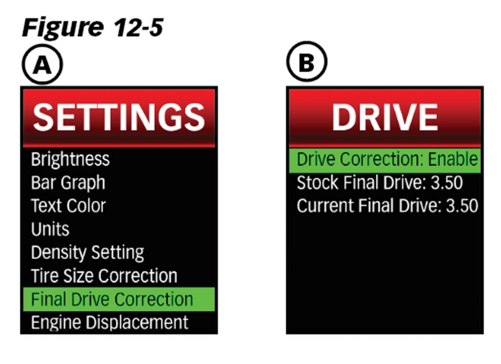
12.7 Final Drive Correction
This feature will allow you to correct the vehicle speed displayed on the iDash when enabled. This will correct the vehicle speed for changes in final drive ratios from what the vehicle was originally equipped with. To correct vehicle speed for drive ratio change:
- Select “Settings“from the main “MENU. Select “Final Drive Correction.” See Figure 12-5, A.
- Select “Drive Correction” to “Enable” or “Disable” the drive correction feature. See Figure 12-5, B.
- Select “Stock Final Drive” to input the vehicle’s stock final drive information. See Figure 12-5, B. Scroll up and down to adjust value.
- Select “Current Final Drive” to input the vehicle’s current final drive information. See Figure 12-5, B. Scroll up and down to adjust value.
- The vehicle speed displayed on the iDash will now be corrected for the current final drive ratio on the vehicle.
NOTE: This will only correct your iDash, not your vehicle’s instrument cluster.
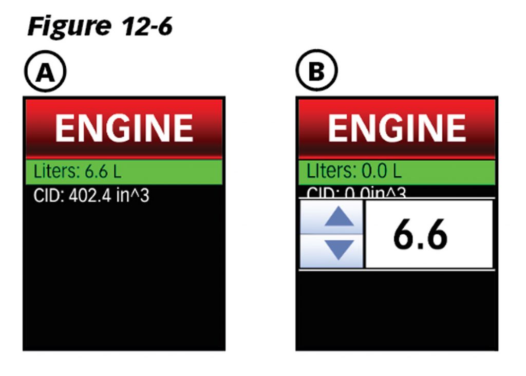
12.8 Engine Displacement
Engine displacement is required to calculate the volume of air being pumped through the engine (CFM). It is also necessary to calculate Cylinder Head Efficiency.
To change the “Engine Displacement” setting:
- Select “Settings” from the main “MENU.” Select “Engine Displacement.”
- Either select “Liters” or “CID” (Cubic Inches of Displacement) to input the vehicle’s engine displacement. See Figure 12-6, A.
- Scroll up or down to adjust the value. Note: The “Liters” and “CID” settings are linked. They will update to match each other when either parameter is changed. The values will adjust to the nearest 0.1-liter.
- Select the desired value to save the setting, and then return to the Gauge Screen when finished.
12.9 Vehicle Selection
The iDash has multiple vehicle selections to accommodate the hardware setup and/or take advantage of additional parameters available.
Each iDash can be set for either “Standard,” “No OBD,” or Vehicle Specific. If using the iDash Banks Bus 1, you can additionally set it to “B-Bus 1.“
Standard Setting
All iDash’s are pre-programmed to the “Standard” vehicle setting and will read parameters common to most vehicles.
No OBD Setting
When using it without communication to an ECU, select the “No OBD” option from vehicle selection.
Vehicle Specific Setting
After selecting your vehicle (if available), more parameters will be available for display on the iDash.
If you connect the iDash with the Derringer Tuner, the iDash will be automatically set to your specific vehicle.
Banks Bus 1 Product Setting (iDash Banks Bus 1 Only)
The iDash Banks Bus 1 connected to the Banks Bus 1 products must be set to “Vehicle Selection,” “Banks Bus 1 Product” in order to communicate with the vehicle and Banks Bus 1 Products.
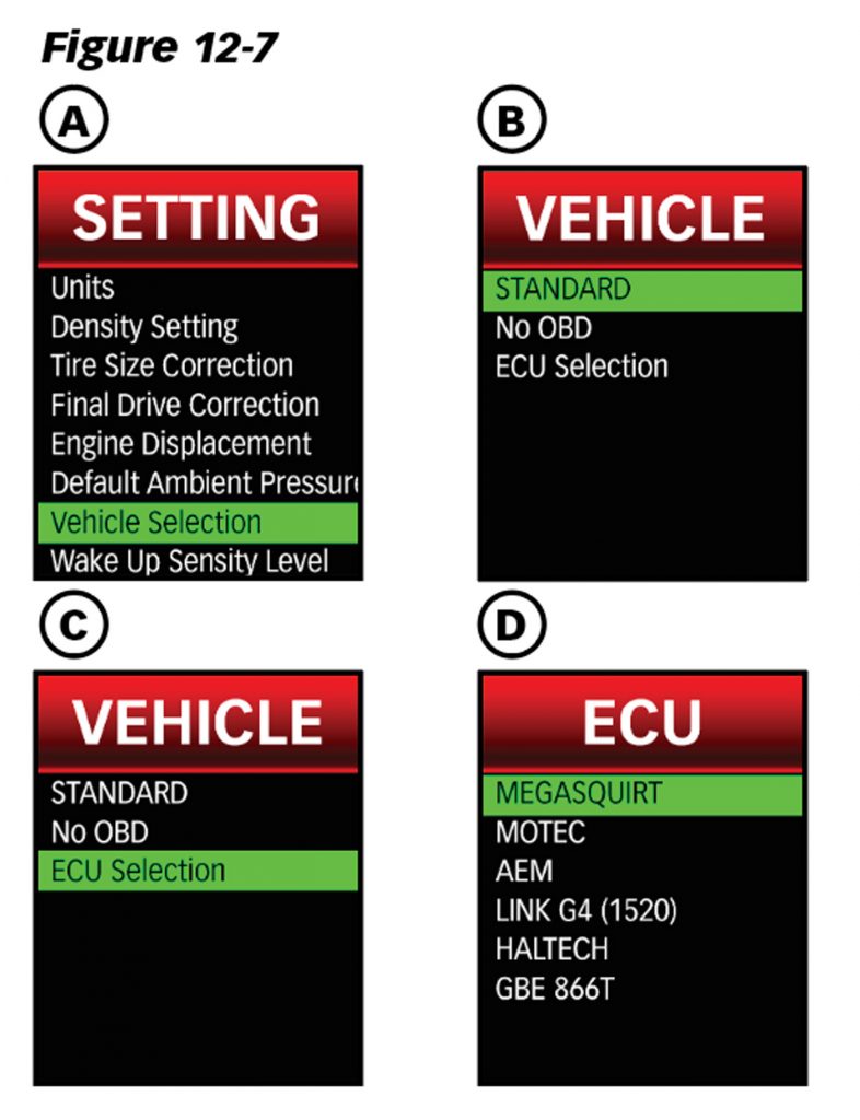
To change your “Vehicle Selection” setting:
- Select “Settings” from the main “MENU.” Select “Vehicle Selection.”
- The initially highlighted setting is the current setting of the iDash. Highlight the desired vehicle setting and select it.
- The iDash will reboot and return to the Gauge Screen.
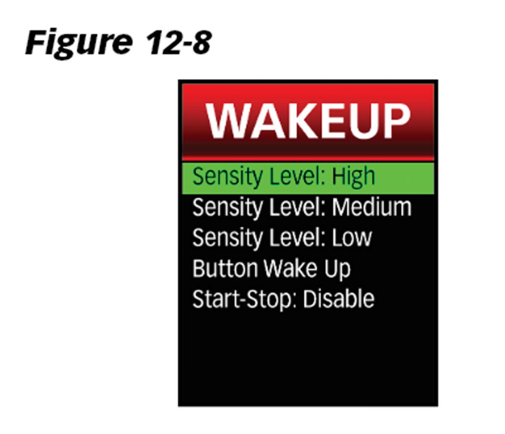
12.10 Wake Up
Sensitivity Level
The iDash’s automatic wake-up uses battery voltage drop when cranking the vehicle. The wake-up sensitivity level allows you to adjust the iDash’s sensitivity to the voltage drop. Some vehicles have greater voltage drops than others and would need to set the sensitivity to the low setting.
NOTE: If the gauge is interfering with OnStar or other similar services, decrease the sensitivity one level lower.
To Adjust the wake-up sensitivity level:
- Select “Settings” from the main “MENU.” Select “Wake-up Sensitivity Level.”
Select the desired sensitivity level (“Sensitivity Level: Low“, “…Medium“, “…High“). See Figure 12-8.
If unsure, set to “Sensitivity Level: Low” and then:
A. Turn off your vehicle and wait for the iDash to go to Sleep Mode.
B. Restart your vehicle and the iDash should start within 10 seconds after startup.
C. If it does not automatically wake-up, press any button to wake. Increase sensitivity level by one and repeat the process.
12.10.2 Start/Stop
For vehicles with engine start/stop functionality: When enabled, the iDash will not shut off when RPM drops below 600 rpm. Instead, the vehicle will check for vehicle communication to the ECU to determine if the vehicle is shut off.
NOTE: It will also take longer for the iDash to go into sleep mode.
To enable or disable “Start/Stop”
- Select “Settings” from the main “MENU.” Select “Wake-up Sensitivity Level.“
- Select “Start-Stop:” to “Enable” or “Disable” this feature. Figure 12-8.
- Return to the Gauge Screen when finished.
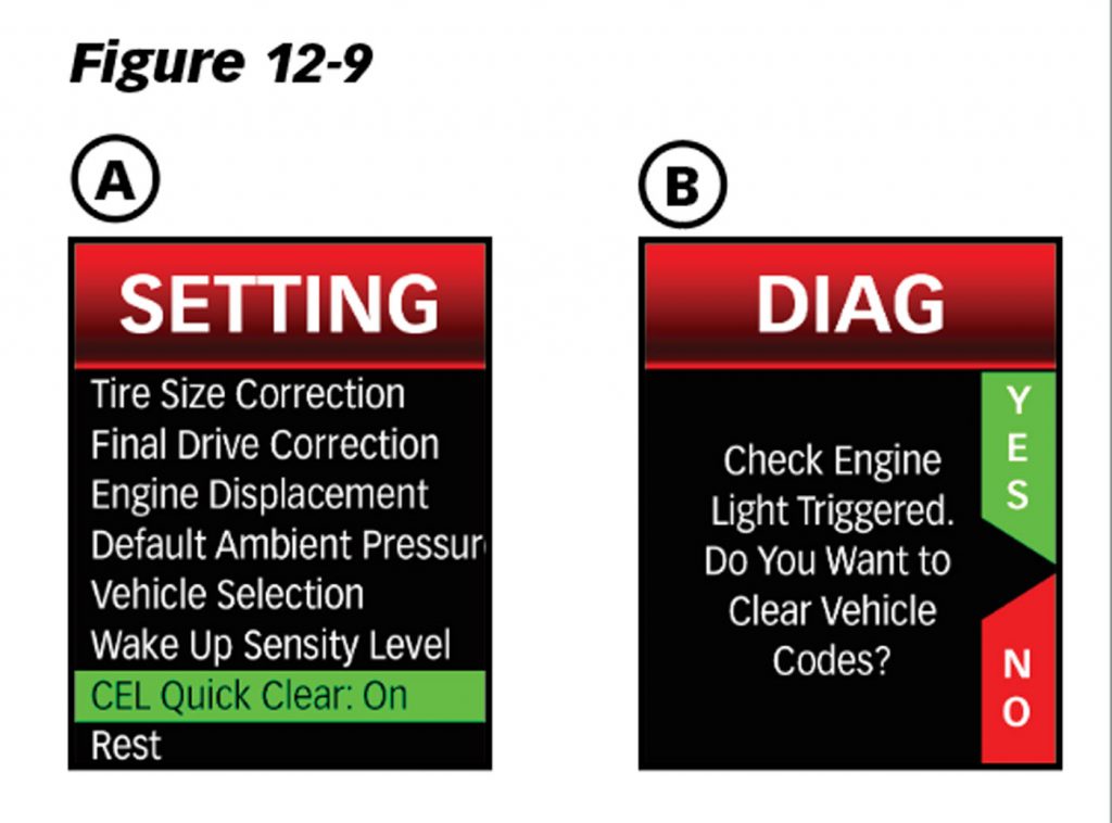
12.11 Check Engine Light Quick Clear
The Quick Clear setting allows you to clear diagnostic trouble codes without having to access the vehicle’s diagnostic menu.
If enabled, a screen will appear once the check engine light is detected to ask if you would like to clear vehicle codes.
NOTE: Check engine light may recur if the cause of the code is not repaired.
- Select “Settings“from the main “MENU.”
- Select “CEL Quick Clear” to toggle ON or OFF. See Figure 12-9.
- Return to Gauge Screen when finished.
12.12 SpeedBrake & Tuner Auto Switch
NOTE: You must have a Banks Tuner and the Banks SpeedBrake connected to the iDash Banks Bus 1 to use this feature.
The “Tuner Auto Switch” feature allows you to have the “Tuner” layout and “SpeedBrake” layout switch automatically while driving.
When does the SpeedBrake Layout appear?
The “SpeedBrake” Layout appears when your vehicle is coasting (greater than 0 mph) while your foot is off the acceleration pedal (0% APP).
When does the Tuner Layout appear?
The “Tuner” Layout appears when your foot is on the acceleration pedal (greater than 0% APP) OR when your vehicle is at a stop (speed: 0 mph.)
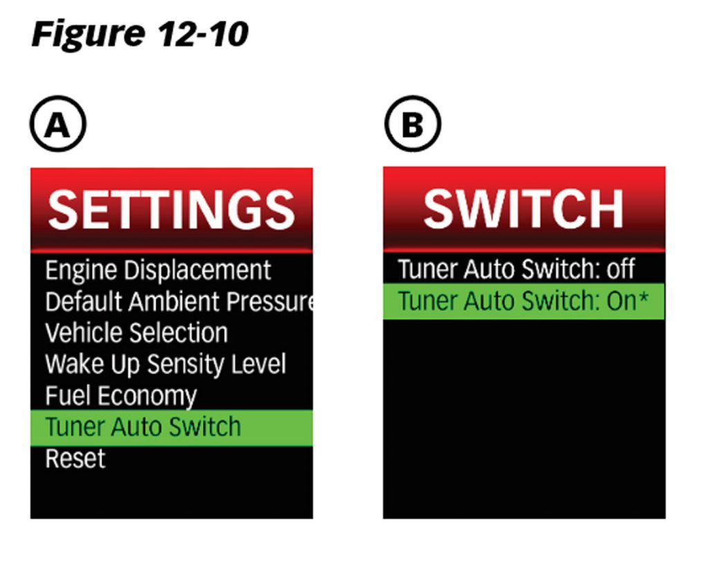
To enable/disable the “Tuner Auto Switch” feature:
- Select “Settings” from the main “MENU.” Then Select “Tuner Auto Switch.” See Figure 12-10.
- To enable, select “Tuner Auto Switch: On.” To disable, select “Tuner Auto Switch: Off.“
- Return to the Gauge Screen when finished.
12.13 Reset
The “Reset” settings allow you to reset the iDash to factory settings.
When calibrating the ambient light sensor, ensure to maintain a stable ambient light environment (Ex: inside the garage). If the lighting changes as the calibration takes place, auto-dimming will change inconsistently and calibration will need to be performed again.
To calibrate the ambient light sensor:
- Select “Settings” from the main “MENU.” Then select “Reset.”
- Select “Calibrate Ambient Sensor” to recalibrate.
- Select “YES” to continue. Ensure that the lighting will stay the same for the calibration. It should only take 30 seconds. Select “NO” to return to the “Reset” menu.
- Return to the Gauge Screen when finished.
The iDash will reboot and return to the “Gauge Screen” if reset.
To reset all iDash settings:
- Select “Settings” from the main “MENU.” Select “Reset.”
- Select “Reset All Settings.”
- Select “YES” to continue. Ensure that the lighting will stay the same for the lighting calibration. Select “NO” to return to the “Reset” menu.
- The iDash will reset and display the pre-programmed Gauge Screen layout.
NOTE: If you have a vehicle-specific gauge it will reset to standard. Therefore you must reset manually in “Vehicle Selection” to your specific vehicle.