
97654 iDash 1.8 DataMonster and Super Gauge – Section 2: Mounting and Connection iDash
INSTALL INSTRUCTIONS
Part #s
66560, 66561, 66562, 66563, 61410, 66760
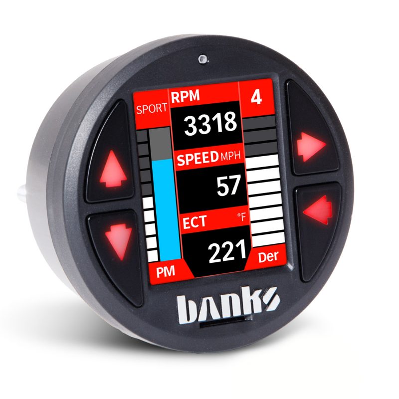
iDash 1.8 DataMonster® & Super Gauge Stand alone instrument for ALL 2008+ OBDII CAN bus vehicles
Please read through the following instructions thoroughly before starting your installation. If you have any questions please visit our Support Page.
Section 2: Mounting and Connection iDash
If installing into vehicle with OBDII communication (standard):

1. Locate the OBDII port in your vehicle.
The OBDII port is located under the dash panel and can be found on either side of the steering wheel. Refer to your vehicle’s owner’s manual if you are having difficulty locating the OBDII port.
2. Connect Banks OBDII Cable to the vehicle’s OBDII port.
NOTE: For some vehicle models the OBDII port may need to be disconnected from its mounting location. Unclip or remove factory screws/bolts to relocate the OBDII port without bending or putting stress on the Banks OBDII cable. Secure the OBDII port under the dash.

3. Route Banks OBDII cable to reach the iDash.
NOTE: You may need to loosen or remove dash panel or covers to install the interface cable between dash crevices or behind dash panels.

4. Connect the Banks OBDII Cable to the 4-pin port on the iDash with the locking tab up.

If you have the standard iDash refer to Figure 2-3. If you have the iDash Banks Bus 1, refer to Figure 2-4.
NOTE: If connecting multiple gauges refer to section 2.7 Advanced B-Bus Network – Multiple iDash of this page.
2.2 OBDII Connection to Six-Gun, EconoMind, SpeedBrake

The OBDII Cable for Banks Bus 1 products has one extra wire coming from the OBDII to connect to Banks Bus 1 Tuners (Six-Gun, EconoMind, SpeedBrake).
Ford 6.0L Power Stroke Applications
For any OBDII Cable for the Ford 6.0L, a connection has to be made to the fuse box (Fuse #22) using a fuse tap.

1. Remove the panel to reveal the fuse panel below the steering wheel and remove Fuse #22.

2. Apply the provided fuse tap before reinstalling.

3. Route the female red terminal connector to the fuse tap. Refer to step 1 in this section.
For the operation of the Six-Gun, EconoMind, and Speed Brake refer to Section 11.
2.3 No OBD or Aftermarket ECU Connection
Refer to iDash Aftermarket ECU Setup Owner’s Manual 97670 for aftermarket ECU wiring instructions.
2.4 General iDash Mounting

1. To install the iDash with provided hardware:
Place the mounting sleeve behind the mounting surface and route the cables to the iDash.
2. Connect cables (i.e. OBDII, Aftermarket ECU Harness, Starter Cable) to the iDash 4-Pin and 6-Pin Ports.
3. Insert the iDash’s studs through the mounting sleeve’s holes.
4. Hand tighten the nylon thumb nuts.
NOTE: If the mount is too tight, the iDash buttons may become unresponsive.
Untighten or sand the aftermarket mount hole (not the mounting sleeve) until you have a clearance for the iDash. If you do not want to use the mounting sleeve, ensure the mounting hole has a minimal press fit so that the buttons remain functional.
2.5 Part Number List

2.6 Simple B-Bus Network – Single iDash
The simple B-Bus network can consist of one iDash Gauge, an In-Cab Terminator OR Jumper Block Termination, a B-Bus Starter Cable, a B-Bus Module, and a Black Termination Cap. See the figure below. If using a single iDash gauge:

If you have a HW Rev 1 iDash:
A. Connect the Starter Cable to the In-Cab Terminator. Step A.
B. Connect the In-Cab Terminator to the iDash 6-Pin Port. Step B.
If you have a HW Rev 2 iDash:
A. Connect the Starter Cable to the iDash 6-Pin Port (Without the In-Cab-Terminator).
B. Confirm that the Jumper Block is connected to the iDash 2-Pin termination. See Figure 2-12.
2.7 Advanced B-Bus Network – Multiple iDash’s

Up to three additional iDash’s can be added to the network. Each additional iDash requires a Y-Cable.
The iDash that has the OBD-II cable or aftermarket ECU harness plugged into it is referred to as the primary iDash. Only the primary iDash is capable of some features, such as:
• Vehicle Diagnostics (Reading/Clearing Codes and Emissions Readiness)
• Setting wake-up sensitivity
• Data logging
• Speed correction settings
To start an Advanced B-Bus Network:

1. If you ONLY have HW Rev iDash’s:
A. Connect the In-Cab Terminator to the iDash 6-pin port. See Figure 2-11, Step A. Only one In-Cab Terminator is required.
B. Connect the Y-Cable to the In-Cab Terminator and the second iDash. See Figure 2-11, Step B.
For each additional iDash, a Y-Cable is used.
C. Connect the Starter Cable to the Y-Cable. See Figure 2-11, Step C.
2. If you have ONLY HW Rev 2 iDash’s:
A. Connect the Y-Cable to the iDash 6-pin port of the first and second iDash (Without the In-Cab Terminator). See Figure 2-11, Step B.
B. Connect the Starter Cable to the Y-Cable.
See Figure 2-11, Step C.
C. Remove extra Jumper Blocks from the added iDash 2-Pin terminations.
See Figure 2-12.
NOTE: Only one jumper block terminator is required.
3. If you have a HW Rev 1 and Rev 2 iDash’s:
Follow either instruction for Rev 1 OR Rev 2, but only use a single terminator in-cab.
2.8 Checking B-Bus Network Termination Type

When using multiple iDash gauges and/or Banks Modules it is very important that there be ONLY one termination in-cab.
Otherwise, your iDash may have trouble communicating to other devices on the network.

Check which iDash Hardware Version you have.
Look behind the iDash as shown in Figure 2-12 & Figure 2-13 to visually confirm the Jumper Block Termination. You can check the “Hardware Rev:” in the “System Information” menu, as shown in Figure 2-14.
If you have Hardware Revision 1, you must use the In-Cab Terminator.

If you have Hardware Revision 2, you will have the pre-installed Jumper Block Termination.
DO NOT use the In-Cab Terminator for HW Rev 2 iDash.