


96425 Monster-Ram Intake with Banks Boost Tube for 2003-07 Dodge 5.9L Cummins
General Installation Practices
1. For ease of installation of your Banks Monster-Ram Intake, Please familiarize yourself with the procedure by reading the entire manual before starting work.
2. Throughout this manual, the left side of the vehicle refers to the driver’s side, and the right side to the passenger’s side.
3. Disconnect the negative (ground) cable from the battery (or batteries, if there are two) before beginning work.
4. Route and tie wires and hoses a minimum of 6” away from exhaust heat, moving parts and sharp edges. Clearance of 8” or more is recommended where possible.
5. The installation should be performed at time when the vehicle has been allowed to completely cool. This installation requires the installer to work near surfaces that may remain hot after the vehicle has been run. Failure to allow the vehicle to cool may result in personal injury.
6. When raising the vehicle, support it on properly weight-rated safety stands, ramps or a commercial hoist. Follow the manufacturer’s safety precautions. Take care to balance the vehicle to prevent it from slipping or falling. When using ramps, be sure the front wheels are centered squarely on the topsides. When raising the front of the vehicle, put the transmission in park (automatic) or reverse (manual), set the parking brake, and block the rear wheels. When raising the back of the vehicle, be sure the vehicle is on level ground and the front wheels are blocked securely.
Caution! Do not use floor jacks to support the vehicle while working under it. Do not raise the vehicle onto concrete blocks, masonry or any other item not intended specifically for this use.
7. During installation, keep the work area clean. Do not allow anything to be dropped into intake, exhaust, or lubrication system components while performing the installation, as foreign objects will cause immediate engine damage upon start-up.
Special Note: Boost-Tube clamp placement and alignment
Stock Intake Elbow and Boost Tube Removal

1. Loosen the clamps that hold the rubber hose at the inlet of the stock intake elbow and slide the hose free of the intake inlet.
CAUTION: Cover the intercooler up-pipe opening with a clean rag to prevent foreign objects from entering the intake tract.
2. Remove the bolt that holds the dipstick on the intake elbow. Save the bolt for reuse. Gently push and move the dipstick and its holder to the rear of the engine compartment to gain access to the engine.
3. Remove the electric heater wire harness from the stock intake elbow by pulling out the plastic pin. Remove the wire harness brackets that are mounted on the intake by removing the nut and the washer.
4. Unbolt and remove the four bolts at the base of the stock intake elbow and remove the intake elbow from the engine. Be careful not to knock any debris into the intake through the electric heater element block.
5. Remove the wires connecting the electric heater element block to the engine and remove the heater element block. Save the fasteners for re-use.
CAUTION: Cover the opening in the intake manifold with a clean rag to prevent foreign objects from entering the engine.
6. Being careful not to scratch or gouge the mating surfaces of the parts, completely remove the stock gaskets from both sides of the heater element block and intake manifold, using a gasket scraper as needed. Clean and dry all sealing surfaces thoroughly.
7. Remove the driver-side boost tube, hoses, and hose clamps. Retain the factory hose and hose clamps at the inlet of the factory driver side boost tube for reuse with Banks Boost Tube. The boost tube is the charge air ducting that routes air from the Charge Air Cooler (CAC) to the intake manifold.
Banks Monster-Ram Intake and Boost Tube Installation

1. Install Banks driver-side boost tube. The driver-side tube uses a 3.5-inch diameter hump hose and spring-loaded clamps at the connection to the Banks Monster-Ram and re-use the factory hose and clamps at the CAC. Keep the hose clamps loose until the Monster-Ram is installed. The orientation of the hose clamps should be position as shown here to avoid clearance issues. Cover the opening of the boost tube to prevent foreign objects from entering the boost tube during the installation.
NOTE: Before slipping any boost tubes and the corresponding hoses, into position, ensure that all connection ends are clean and free of any oil residue and contaminates. Clean all connection points with a non-oil based solvent such as Acetone, Mineral Spirits, Denatured Alcohol or Lacquer Thinner. Read and follow the manufactures operation instruction for non-oil based solvent cleaner.
2. Reinstall the electric heater element block onto the intake manifold, placing one of the supplied gaskets between it and the intake manifold. Reattach the three electrical connections to the heater element.
CAUTION: The Banks studs have different threads on each end.
3. Make sure that the M8 ends go into the engine intake manifold. The two shorter studs go on the passenger side (closest to the valve cover). Apply blue medium strength thread lock compound at the M8 ends and hand-tighten the studs into the intake manifold.

4. Using the two 5⁄16”-24 hex nuts supplied, tighten the studs into the intake by threading both nuts onto the stud, then tighten the nuts against each other with two 1⁄2” open-end wrenches. Tighten and torque the stud to 3-5 ft-lbs (35-60 Inch Pounds) by turning the top nut. Remove the nuts from the stud by using two open-end wrenches to loosen the nuts in relation to each other. Repeat the process for each stud.
5. If your vehicle is NOT equipped with a factory ground strap on the intake heater, install the supplied ground strap from the intake heater to the engine. Put a 6-mm washer onto the bottom intake heater stud, leaving the factory heater nut installed. Next, install the smaller diameter ground strap terminal over the stud and retain with a 6-mm washer and nut. Route the other end of the ground strap to the threaded section on the engine and retain with a SAE washer and M8-1.25x 16 bolt. See the previous illustration.

6. Using a flat screw-driver, loosen the clamp that holds the rear injector wire harness on the engine valve cover. Disconnect the injector wire harness from its connection. See the figure. Remove the bracket used to hold this wire harness to the stock ram. Route this harness underneath the heater harness and around the fuel by-pass valve as shown below. Place the wire harness back in the clamp that is on the valve cover and re-connect the wire harness. Make sure there is no sharp bends in the wire harness, and secure it by re-fastening the clamp. Secure the wire harness with the supplied cable ties.

7. Disconnect the MAP and the FRP sensors and relocate the wire harness in front of the heater harness as shown here. Reconnect the sensors.

8. Slide the second provided intake gasket over the four studs and set the Monster-Ram in place on the studs. Twist a Stat-o-seal washer over the driver side two studs, then over each stud install a flat 5⁄16” AN washer. Install a 5⁄16 -24 Nylock nut on each stud and tighten all four evenly between 11-12.5 ft-lb (140 to 150 Inch Pounds.)
CAUTION: Use only handtools when tightening the Monster-Ram. Tighten snugly but do not overtighten. Damage to the Monster-Ram casting can result from the use of pneumatic tools or excessive tightening.
9. The plastic pin on the heater wire harness will not be used to secure to the Monster-Ram. Use a supplied cable tie to secure the harness away from any heat source.
10. Plug off any unused ports with supplied pipe plugs.

Note:
The 1/8” NPT ports shall only be used for installing sensors for measuring air temperature, pressure, or flow. Sensors installed to these ports shall have a fitting of 1/8” NPT and shall not be connected to the vehicle’s electronic control units. In addition, factory sensors that come equipped on the vehicle shall not be disconnected and shall not be relocated to the ports. The ports, when not used, shall be closed off with the supplied plugs.
11. Remove all rags from the boost tube opening and reconnect the rubber hose from the boost tube to the Monster-Ram and tighten the clamp to 100-inch-pounds.
12. Rotate the dipstick bracket and align the dipstick bracket hole to the hole on the Monster-Ram. Mount it to the Monster-Ram casting using the original factory bolt.


NOTE: For 2004-2007 model vehicles, locate the supplied corrugated loom in your kit and install over the main connector wires to protect it from rubbing against the dipstick.
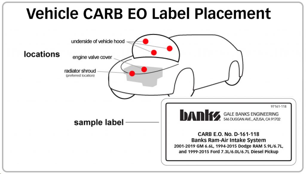
CARB EO LABEL
Please use the following CARB-approved emissions label and EO label location guidelines. We generally use the radiator shroud location.
Reconnect the batteries. The Banks Monster-Ram installation is now complete!