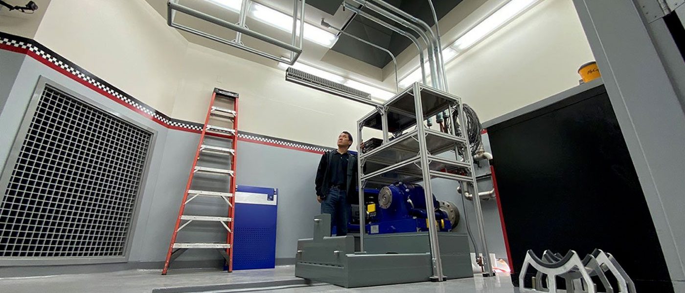
Dyno Cell #2 Progress Report
Well, it’s all coming together—first virtually and then in reality. Visualized and designed in CAD, the components of the dyno are were assembled in the computer first before the systems were put together in the actual room. It’s a process that helped us make the most use of the space available, including relocating a previously floor-mounted high-efficiency liquid-coupled charge air cooler. This vital component once lived its life on the floor usually in front of or beside the engine that was being tested, with its water and boost lines snaking across the floor. The dyno room refit sees the important component cage mounted to the ceiling above the engine, giving engineers better access to the engine and components being tested.
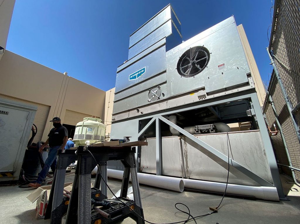
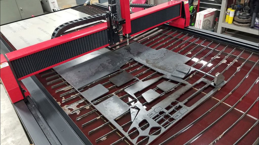
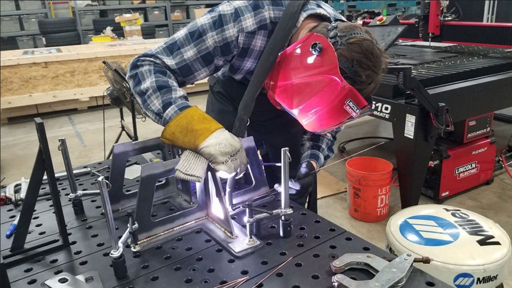
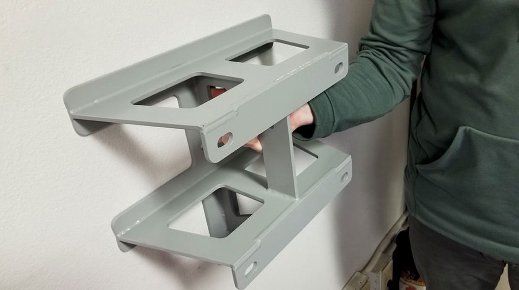
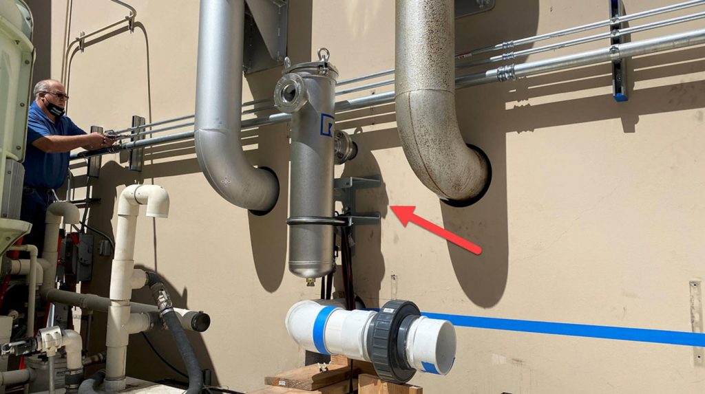
With its new water cooling tower assembled and now in place the Banks engineers are hard at work playing the part of plumbers. Gallons of water coming into and going out of the dyno cell require braces to be made to keep them steady while under pressure and the strain of an 800 hour NATO test. These braces are designed in CAD, plasma-cut with our new Lincoln 4510, and are weld assembled. The 5’X10′ plasma table makes snipping out the designed parts a breeze with little to no prep, making for incredibly sturdy and quickly made part. The team is working as fast possible so we can bring you more videos from inside the new dyno cell!
