
97763 Banks AFR Module with Wideband O2 Installation
INSTALL INSTRUCTIONS
Part #s
66564
---------------- For use with Banks Analog Module
Installation requires the use of a welder, cutting into the exhaust system, and is not a direct bolt-on for most vehicle applications.
Please read through the following instructions thoroughly before starting your installation. If you have any questions please visit our Support Page.
| Part Number | Description | QTY |
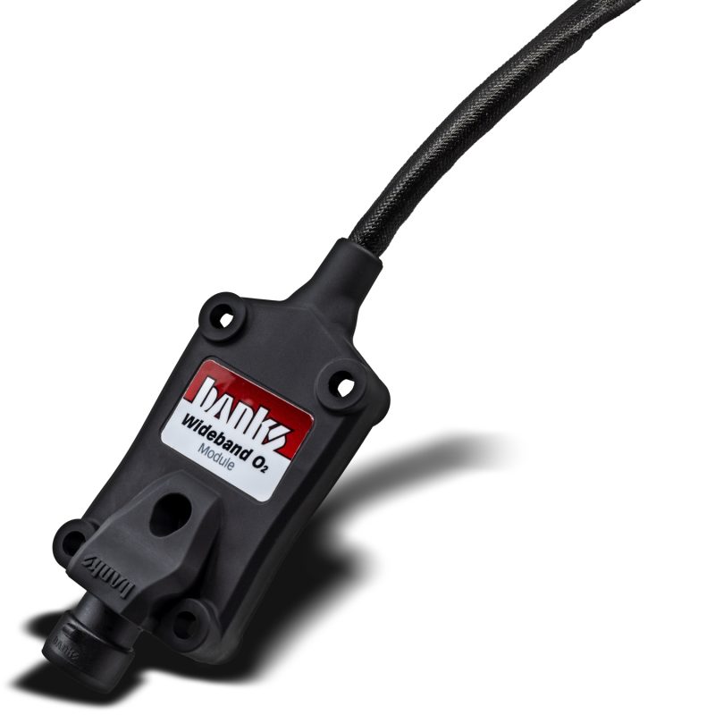
| 45103 | Banks AFR Module | 1 |
| 45104 | Wideband O2 Sensor | 1 |
| 52248 | O2 Weld Bung | 1 |
| 62010 | Cable Tie | 8 |
Installation Note
The Banks AFR module and O2 sensor are intended to be installed and used by experienced mechanics, technicians, automotive enthusiasts, or race teams. Installation requires the use of a welder and cutting into the exhaust system and is not a direct bolt-on for most vehicle applications.
Data configuration varies slightly between iDash Pro and iDash Classic. See videos above and/or text instructions below.
Warning
The Lambda Sensor is fitted from the factory with a calibrated trimming resistor embedded in the sensor connector. If the factory sensor connector is cut off and replaced with another type, Banks Wideband O2 Module will not operate correctly.
General Installation Practices
Banks AFR Module with Wideband O2 Sensor Kit Installation
1. Mount the O2 sensor bung.
Go to a local muffler shop or use your own shop equipment to to weld on the included O2 sensor bung.
The bung will need to be placed at least 36 inches from the exhaust ports to avoid excessive heat.
The bung will need to be placed at least 36 inches from the exhaust system’s open end to avoid incorrect atmospheric oxygen readings.
The bung will need to be placed approximately 6 inches after the collector and before the catalytic converter.
On turbo applications, the bung should be placed approximately 24 inches after the turbo but before the catalytic converter.
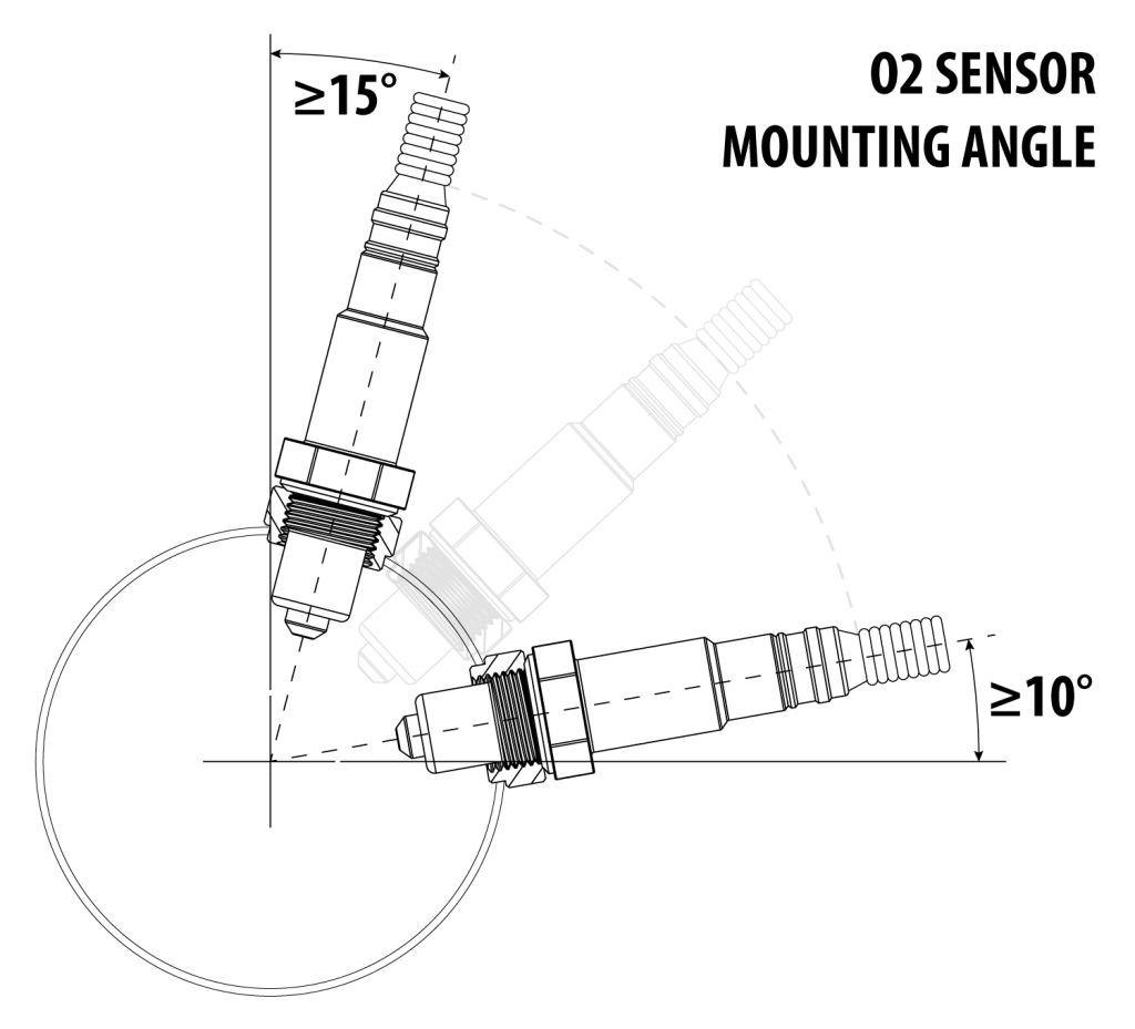
Be sure the bung is angled at least 10° above horizontal, with the probe pointing downward. The O2 sensor tip must face downward to avoid condensation accumulation.

2. Anti-seize note.
Before installing the O2 sensor, check the threads for anti-seize compound. If there is none, add it to the threads at this time.
WARNING: Do not let the anti-seize compound come in contact with the sensor probe.
3. Install the O2 sensor.
Using an O2 sensor socket, torque the sensor to 35lb/ft.
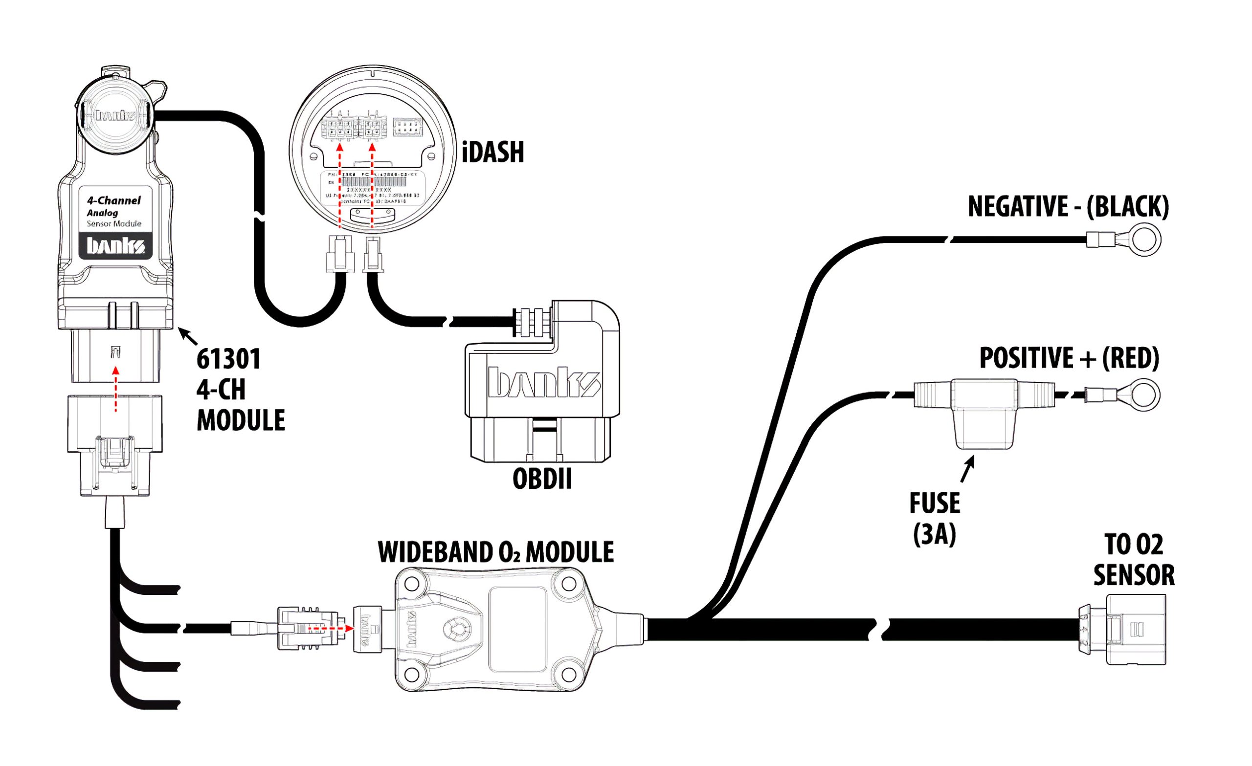
4. Install the AFR module.
Place the AFR Module in the engine compartment and route the O2 sensor cable to the sensor.
NOTE: Be sure to fasten the cable away from moving parts and heat sources.
5. Connect the AFR module cable to the O2 sensor.
Push the plug together until it clicks.
6. From the AFR module, connect the positive and negative wires to a keyed-on 12v power source.
7. Plug one of the cables from your 4-channel module into the AFR module.
Connecting to iDash: Pro
- To begin, press the Right Arrow button to enter the Menu.
- From the list, choose “Banks Modules.”
- Scroll down to the “4ch Analog 1” and select.
- Choose which channel has the AFR module connected. (e.g. CH-1A if on CH-A cable)
- Select “Enable” to activate.
- Next, go to “Change Mapped Parameter.”
- Choose “Engine Performance – Fuel”
- Select “B-Bus Lambda 1/1”
- Hit the back button 3 times to return to the Main Menu.
- Select “Gauge Selection.”
- Choose which field you wish to display AFR.
- Select “Category.”
- Select “Engine Performance – Fuel”
- Next, choose “B-Bus Air Fuel Ratio Bank1 Sensor1.”
- Hit the back button until it returns to gauges
Connecting to iDash Classic:
- To begin, press the Right Arrow button to enter the Menu.
- From the list, choose “Banks Modules.”
- Scroll down to the “4ch Analog 1” and select.
- Choose which channel has the AFR module connected. (e.g. CH-1A if on CH-A cable)
- Select “Enable” to activate.
- Next, go to “Change Mapped Parameter.”
- Choose “Engine Performance – Fuel”
- Select “Air Fuel Ratio Bank1 Sensor1”
- Select “Type”
- Select “Voltage”
- Select “Calibration”
- Select “Custom Table 1” or any other available table.
- Select “Config Custom Table 1”
- Set table size to “02”
- Select the first option, which should be “1: 0.00v, 0.0,” and make sure both options are “0.0” and. “0000.0”
- Select the second option, which should be “2: 0.00v, 0.0,” and set the options to “5.00” and “0073.5” for gasoline engines, or “5.00” and “0072.5” for diesel engines
- Return to the Main Menu.
Displaying on Gauges
- Select “Gauge Selection”
- Choose which field you wish to display AFR.
- Select “Category”
- Select “Engine Performance – Fuel”
- Next, choose “Air Fuel Ratio Bank1 Sensor1.”
- Hit the back button untioll it returns to gauges.
Changing the unit of measurement:
- To change the unit of measurement, hit the right arrow to enter the Main Menu.
- Select “Settings.”
- Select “Units and Density.”
- Scroll down to “Air Fuel Ratio” and select.
- Choose which option best suits your setup.
- Press the back button until you return to the gauge screen.