97738 Monster-Ram Intake System for 2007.5-18 RAM Chassis Cab 6.7L
INSTALL INSTRUCTIONS
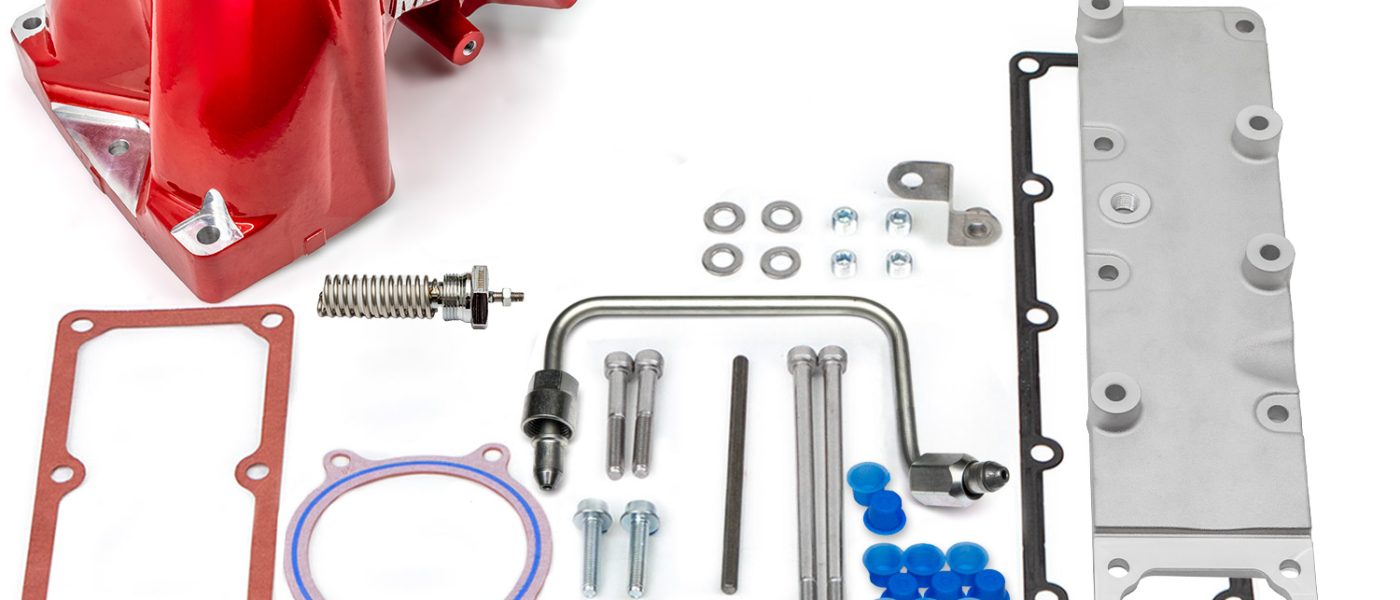
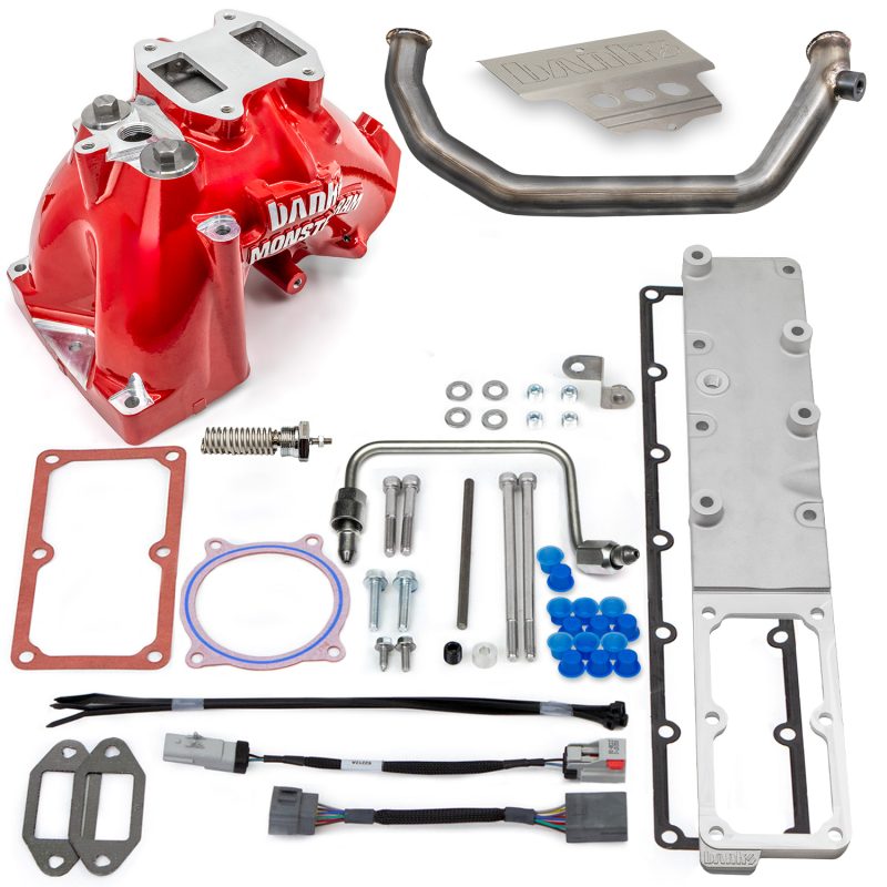
Part #s
42804-R, 42804-N, 42806-R, 42806-N
Monster-Ram® Air Intake
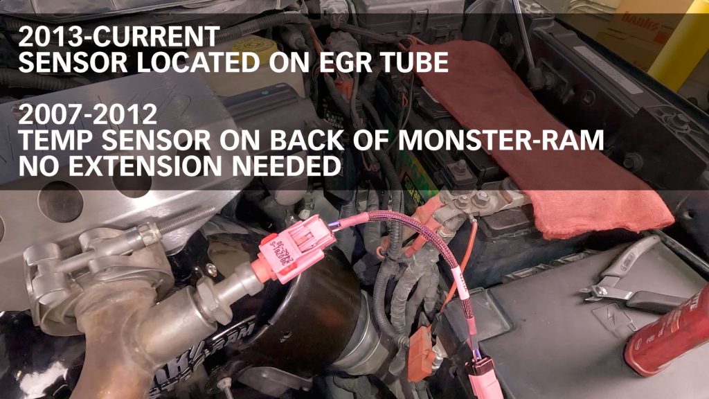
2007.5-2012 RAM Chassis Cab 3500/4500/5500 6.7L Cummins
2013-2018 RAM Chassis Cab 3500/4500/5500 6.7L Cummins
Small parts in kit will vary depending on Model Years
(2007.5-12 vs 2013-18 )
Does NOT fit Freightliner or Motorhome vehicles featuring the Cummins 6.7L Engine as emission, EGR systems, boost tubes, and intake elbow are unique to those vehicles.
Please read through the following instructions thoroughly before starting your installation. If you have any questions please visit our Support Page.
Monster-Ram w/Intake Plate Install Video
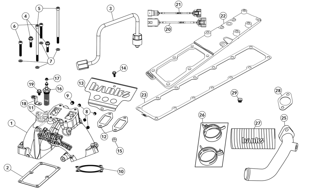
2007-12 Monster-Ram Chassis Cab Diagram
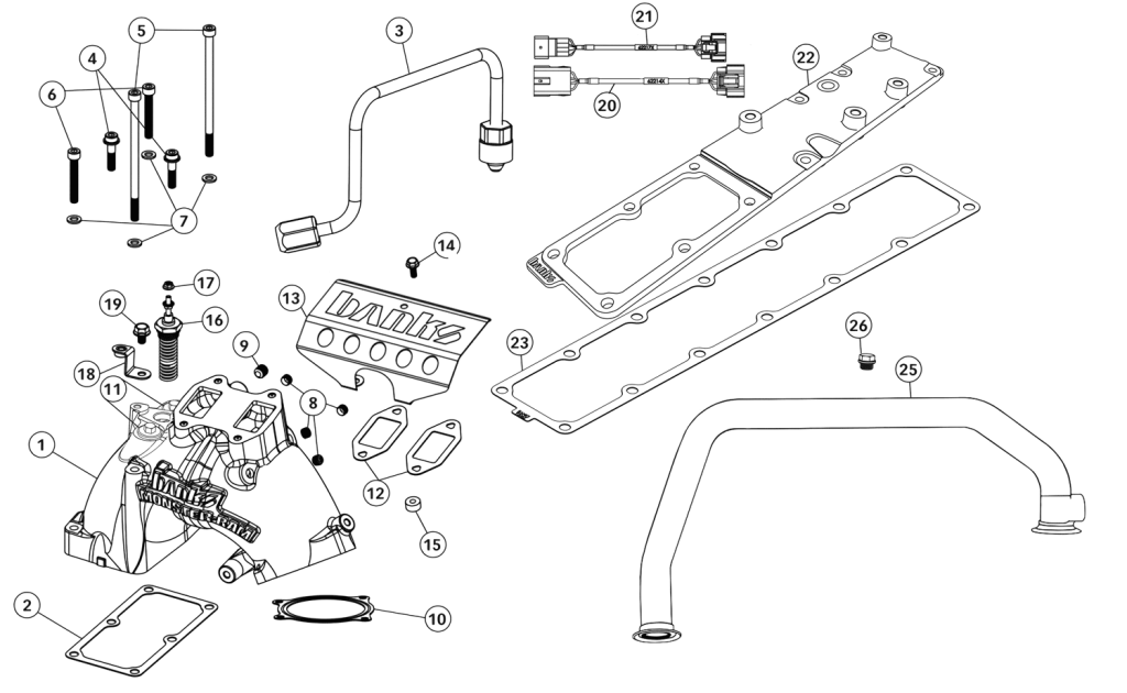
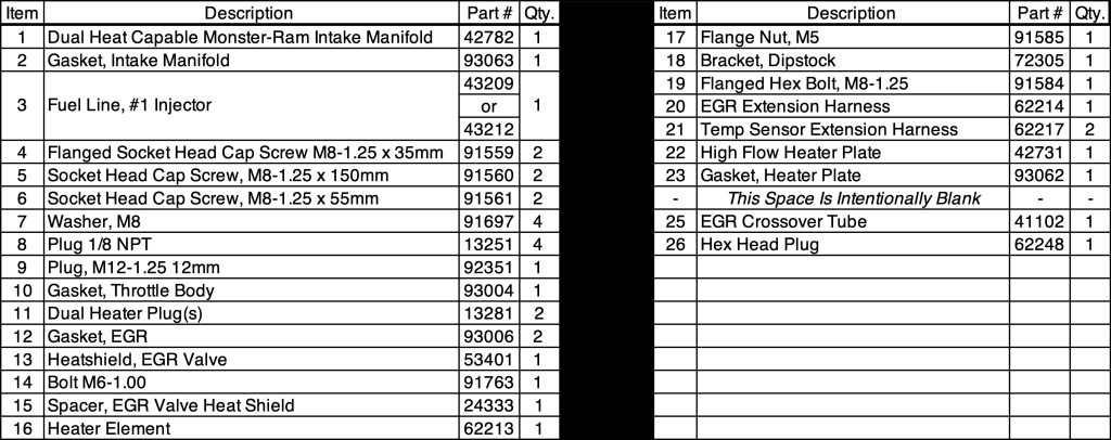
2013-18 Monster-Ram Chassis Cab Diagram
Note: The billet heater plate, Item #22, is transitioning to a cast design (42731) with integrated fuel rail spacers. If your kit ships with this cast heater plate, the fuel rail spacers will not be included or used during installation.
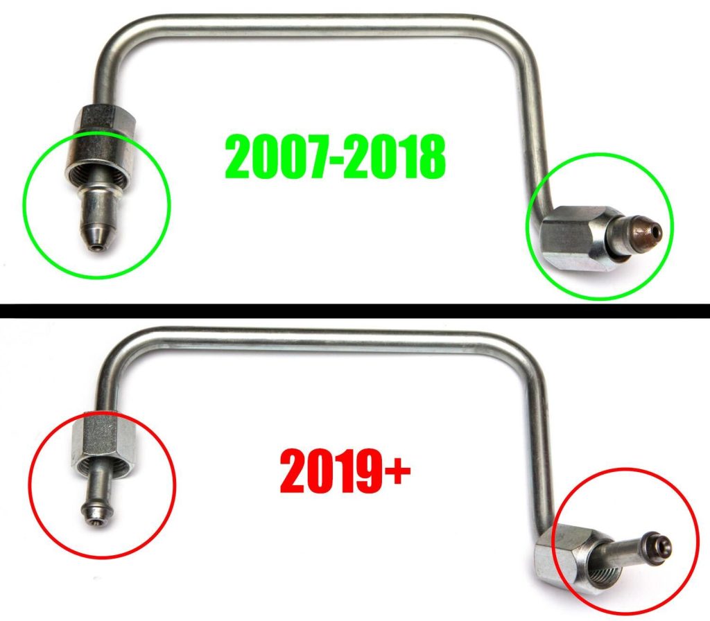
In effort to make sure you have the right kit for your model year. Visually check which fuel line is included in your kit before starting installation.
Chassis Cab Owners
Take note, this install guide is based on the existing RAM 2500/3500 Pickup Truck models. While the engine and general install procedure are the same, specifics of sensor placement and emission system locations vary on RAM 3500/4500/5500 Chassis Cab Trucks.
Details regarding these changes are shown with matching photos, diagrams and specific install steps in this manual.
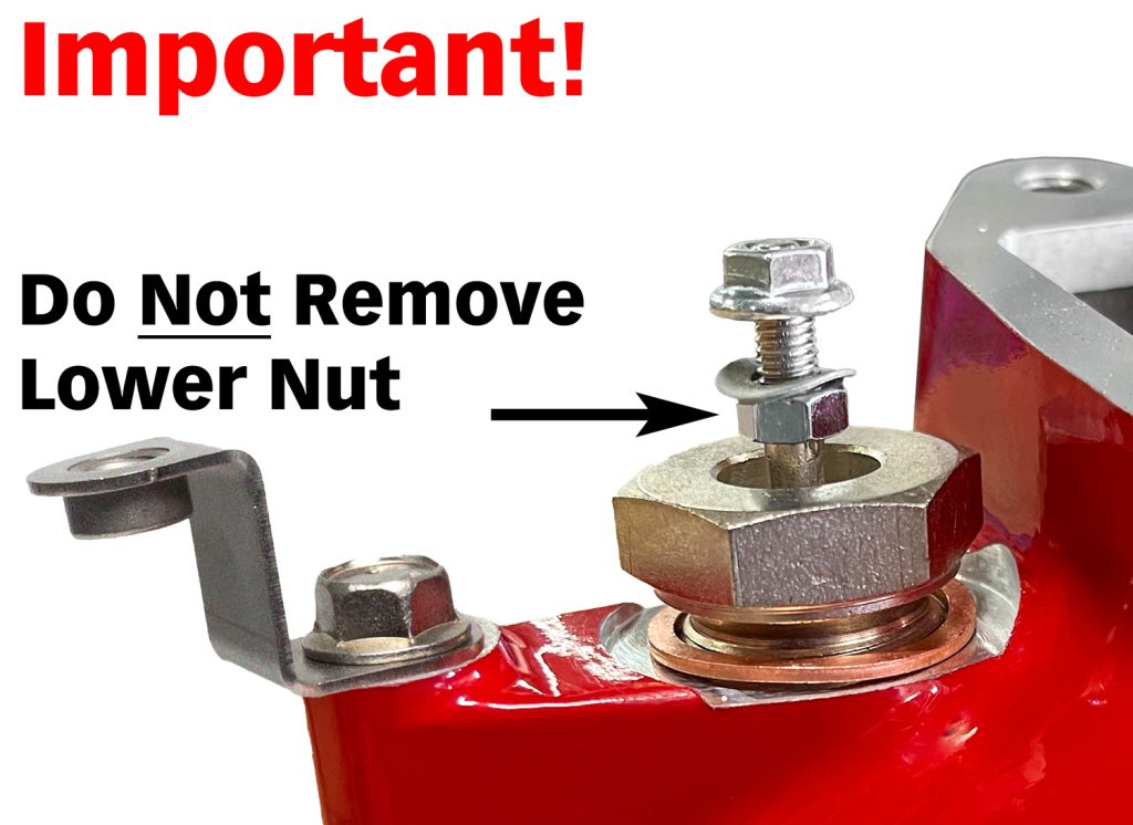
IMPORTANT!
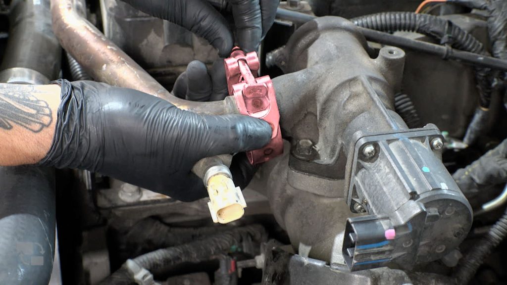
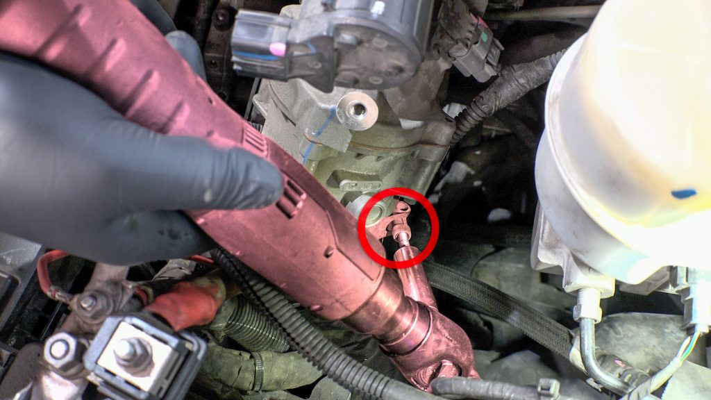
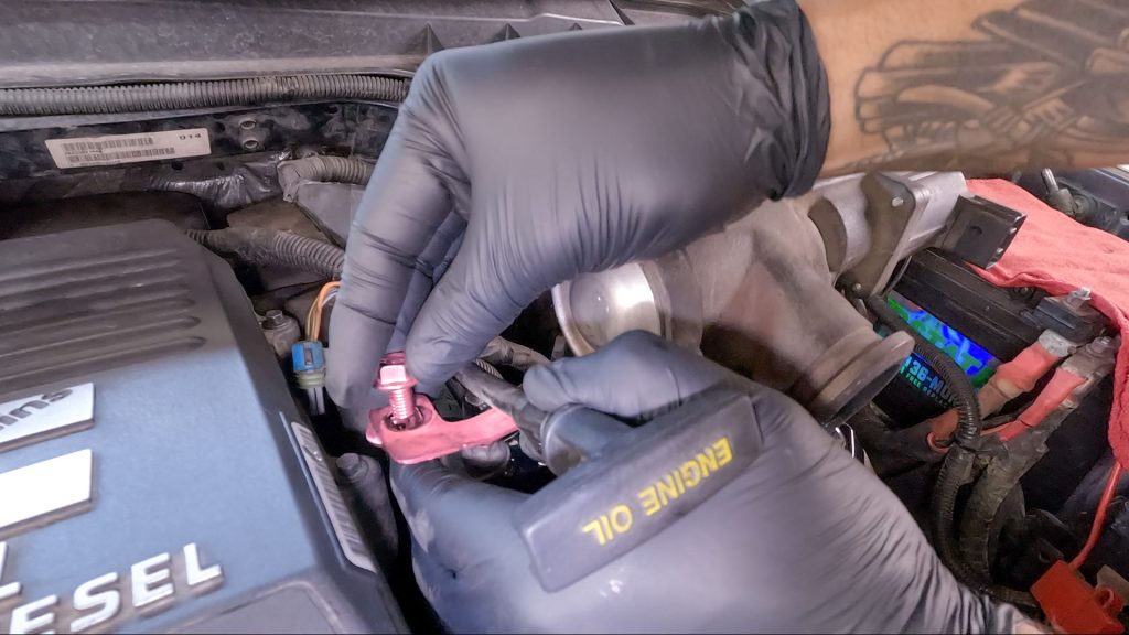
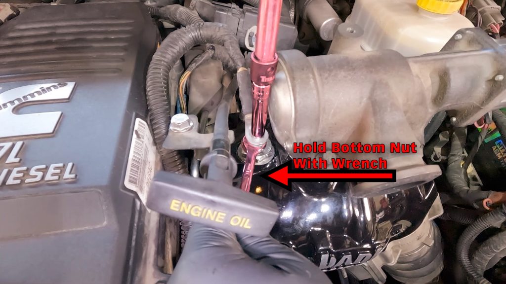
Coil heater preparation: Remove the top hex nut from the threaded post. You will replace the nut with the supplied flange nut as shown. The lower nut must not be removed from the heater coil. The lower nut must remain 1/8″ above the coil heater body.
Take care when installing OEM heater wire ring terminal, it must be sandwiched between the upper and lower nut. If the lower nut is too low, the ring terminal could contact the body of the coil and will short out.
When tightening the nut, it is very important to use a 10mm wrench or socket on the top nut and an 8mm open-end wrench on the bottom nut to prevent the threaded post from rotating. If the threaded post rotates, it can break the ceramic insulation it’s surrounded by.
If the OEM heater wire touches other metal components, an open short will occur.
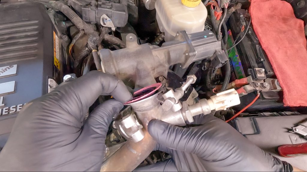
Copper washer: All kits now ship with a copper crush washer. Place this washer between the coil heater before screwing it into the Monster-Ram.
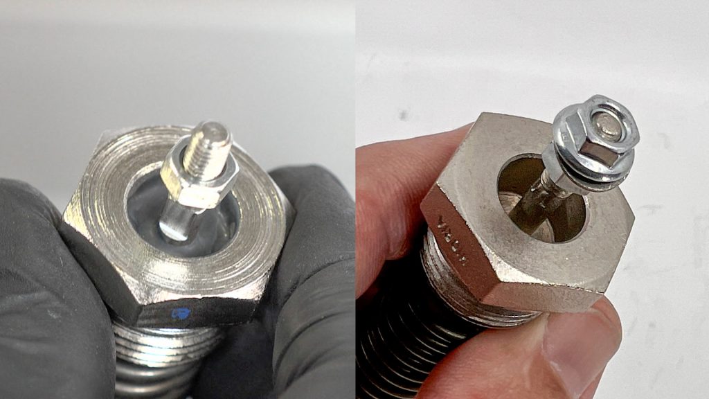
Coil-Heater Variants
Your kit may include one of two different style heater coils. One with a visible ceramic insulator, or one that isn’t visible. Both offer the same level of heating performance.
Installing a Dual Heater Upgrade?
See our Dual Heater and Billet Heater Upgrade supplement for important wiring information and diagrams.
OEM Harness and Sensor Removal
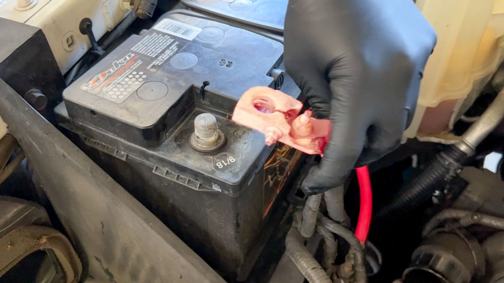
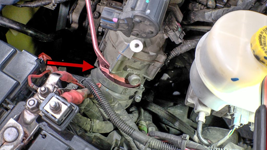
1. Disconnect Batteries
Place a rag around each of the negative battery cable ends; this will prevent them from touching the battery again and arcing during the install as you work.
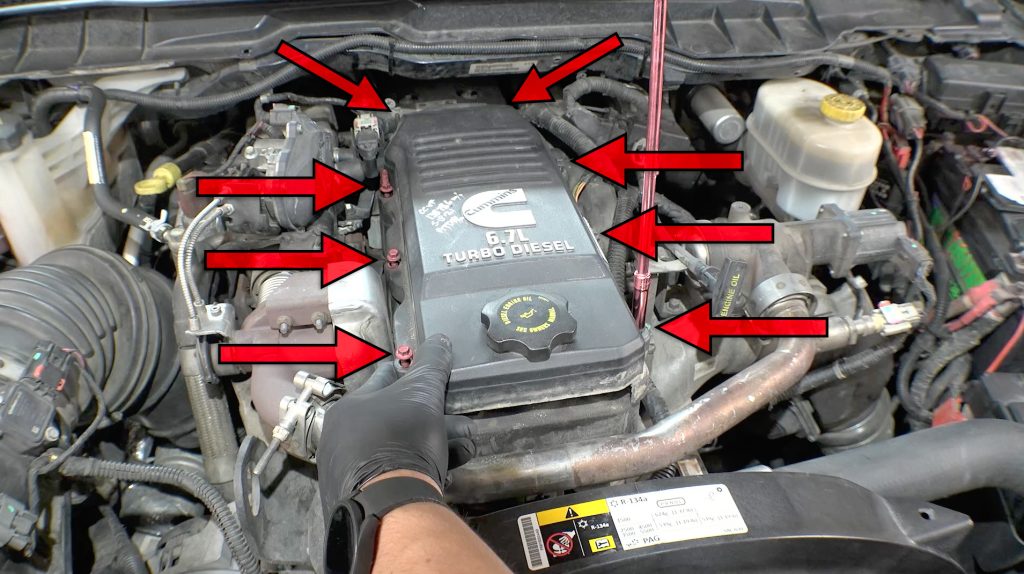
2. Remove Engine Cover
Remove engine beauty cover. Use an 8mm deep socket to remove the four bolts holding the cover down.
3. Remove Dipstick
The dipstick needs to be removed for the cover to come off.
4. Remove Engine cover, Reinsert Dipstick
5. Remove Cable Tie Downs
Use a panel popper tool or pliers
Note: The 2 bolts with studs extending up past the head are to be located on the left rear of the cover.
6. Remove Cable Tie Downs
7. Remove Engine Cover Bolts
There are 8 bolts holding on the cover. A wobble extension and placing the socket on the bolts first helps.
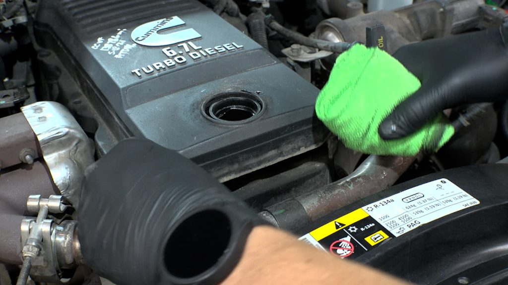
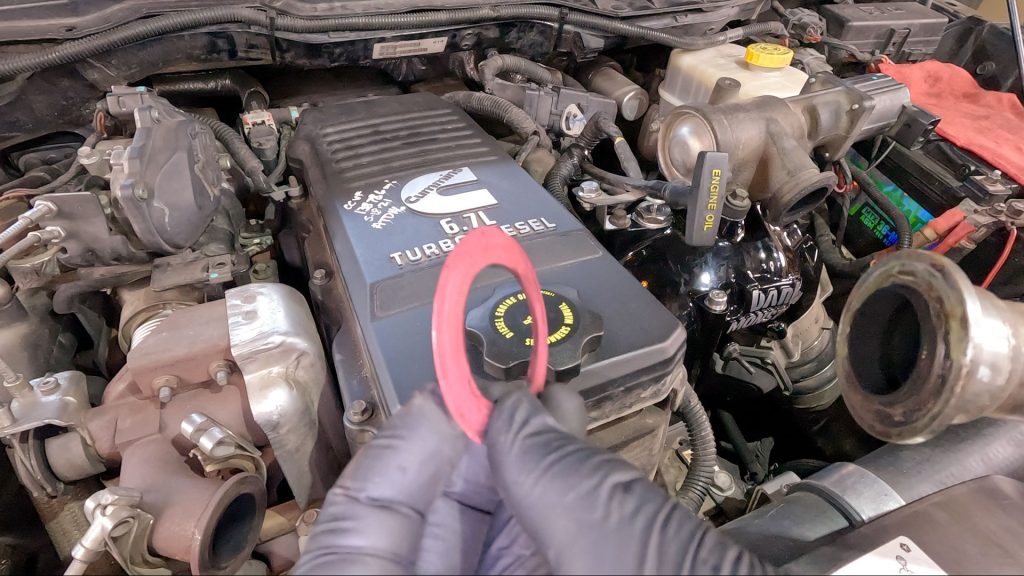
8. Remove Oil Fill Cap
9. Place Rag Over Filler Neck
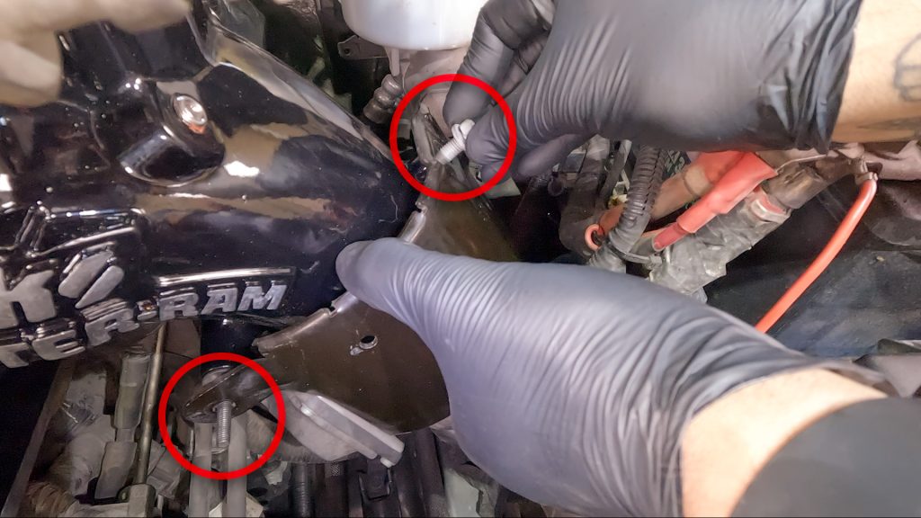
10. Remove Bolts Holding Cross Over Tube Bracket
This bracket will not be reused.
11. Remove Rag, Set Down Cover
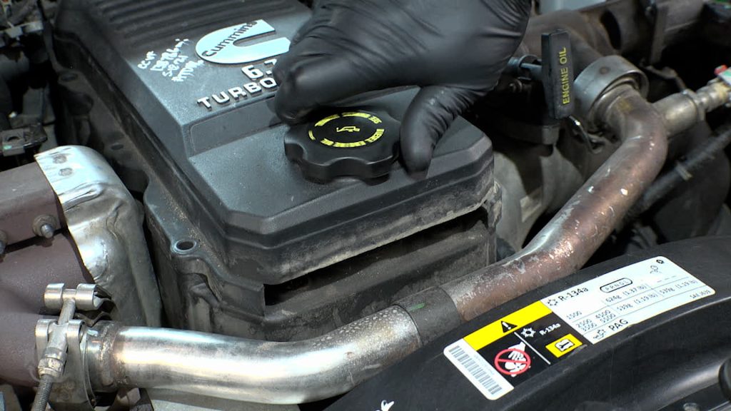
12. Install Oil Filler Cap
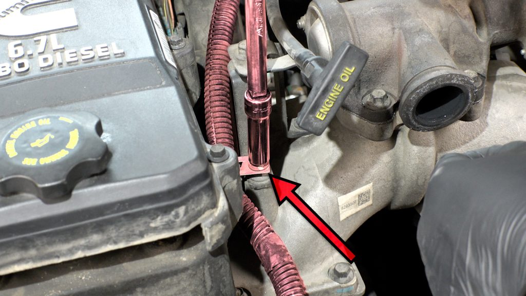
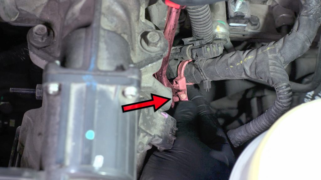
13. Remove Bolt Under Center of EGR Crossover Tube
14. Remove and Dispose EGR Tube P-Clamp
15. Reinstall 8 Engine Cover Bolts – Studs in Rear Passenger Side
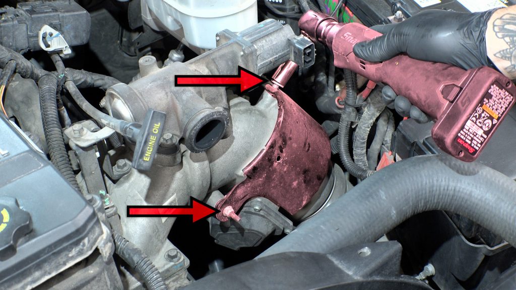
16. Unlock Temp Sensor Plug From EGR Crossover
Use a flat-blade screwdriver or pry tool to push the slide-lock.
17. Remove Temp Sensor clip by Pinching It
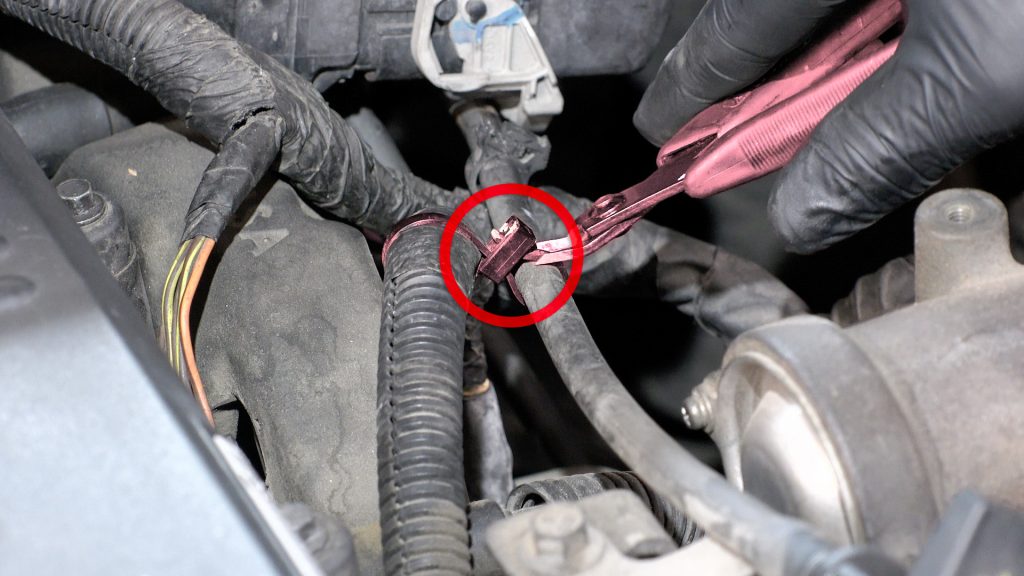
18. Remove EGR Valve Plug
Press the locking tab, press the plug forward to release tension, then pull back to remove.
19. Remove EGR harness cable tie
A) EGR Tube Removal (2007.5-2012) for
2013-2018 See EGR Removal “B”
20A. Loosen EGR Clamp Driver’s Side
This will ease access later, use a small flat blade to release the clip.
21A. Flip EGR Clamp Upside Down for Easy Access Later
Do not remove the clamp yet.
22A. Loosen EGR Clamp Passenger Side
Do not remove this clamp yet (A gasket will slip out and fall if you do)
23A. Release Driver side EGR Clamp
Keep a hand under the clamp incase the gasket comes loose.
24A. Release Clamp & Remove Gasket
Catch the gasket and put aside for later, this will be used again.
25A. Release Passenger Side EGR Clamp
Apply pressure to keep the gasket in place and keep your hand under the passenger side clamp to prevent the flat EGR gasket from falling into the engine bay.
26A. Catch EGR Gasket From Falling
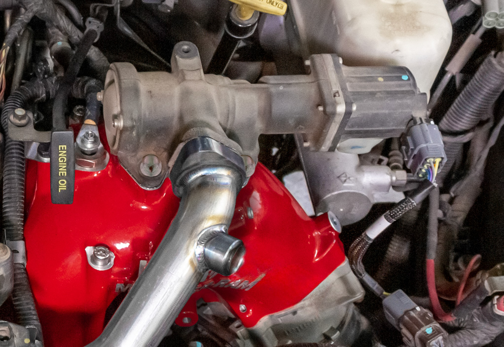
B) EGR Tube Removal (2013-2018)
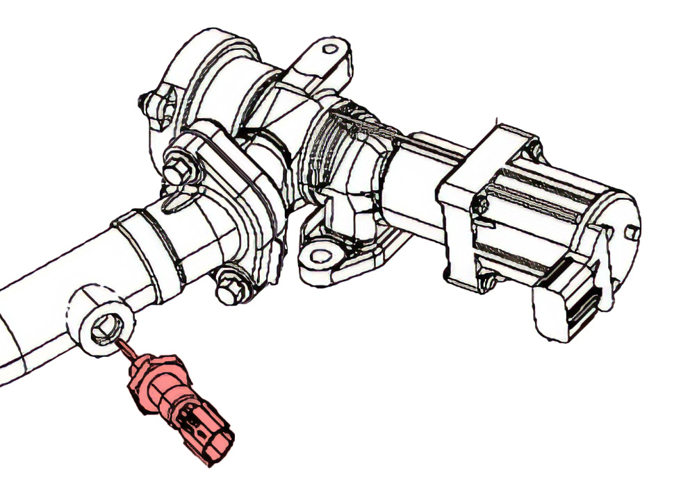
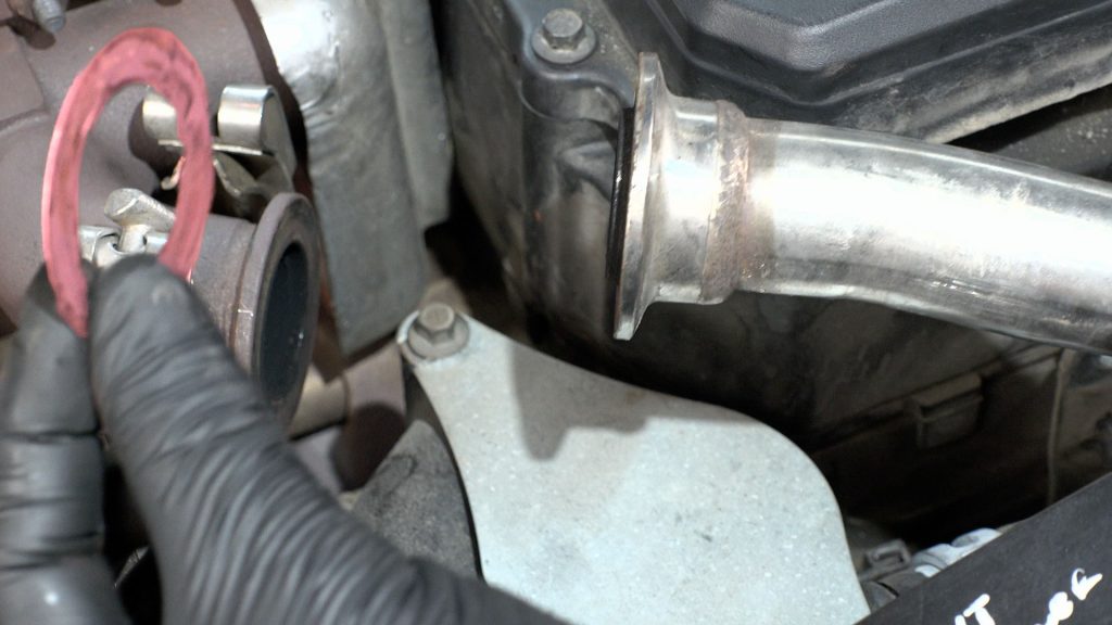
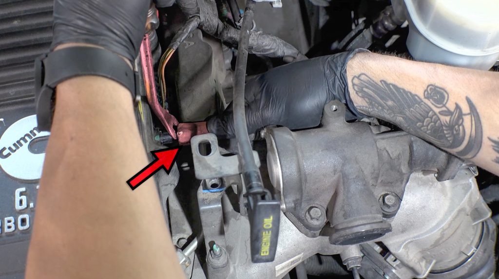
20B. Remove Screw in EGR Temp Sensor From EGR Crossover Tube.
This sensor will be reused later with the Banks Driver Side Crossover Tube.
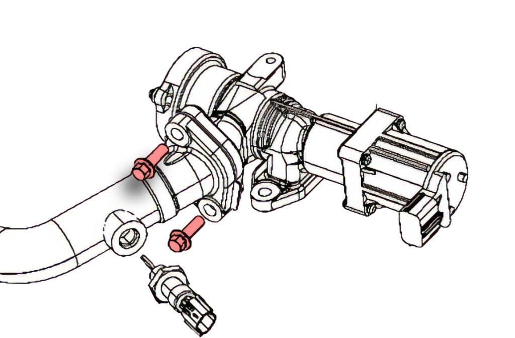
21B. Loosen and remove EGR Tube bolts on Driver’s Side
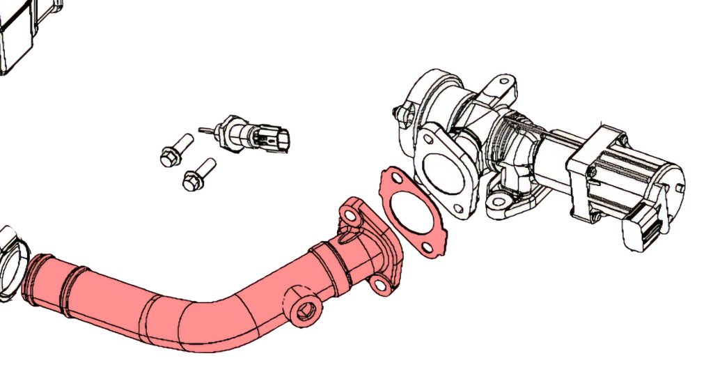
The OEM gasket and tube will not be used with the Monster-Ram. A new 2 Bolt Gasket is provided.
Put the two bolts for the EGR valve and Temp sensor aside; they will be reused.
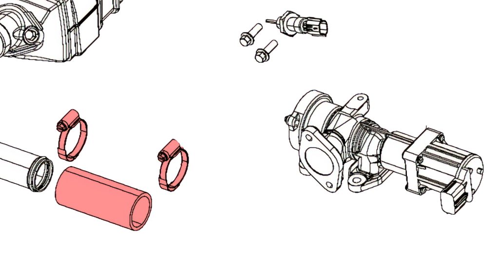
22B. Remove Center EGR Hose
A New Banks Silicone Hose and Clamps are provided for use later in the installation.
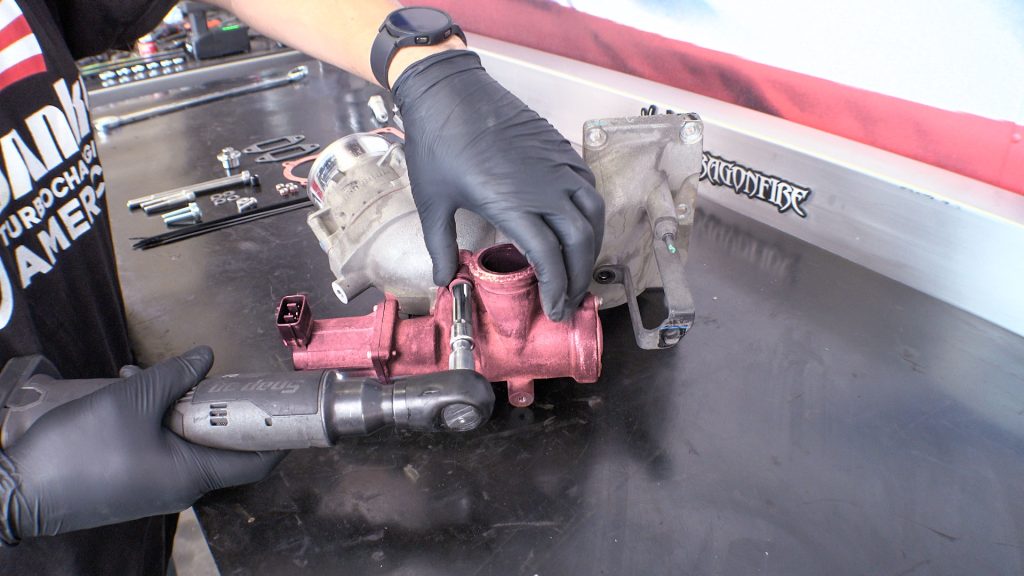
Intake Elbow Removal
23. Remove Throttle Heat Shield
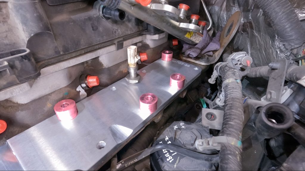
24. Cut Dipstick Tube Zip Ties
Free up the thick 12V wire for the grid heater.
25. Remove 12V Harness P-Clamp
26. Remove Heater cable from Terminal
Relocate the wire out of the way once the free.
27. Remove Dipstick Tube Bracket
28. Bend Tube Up Slightly
The Monster-Ram is slightly taller than the factory Intake Elbow; you’ll fine-tune this bend after the Monster-Ram is installed.
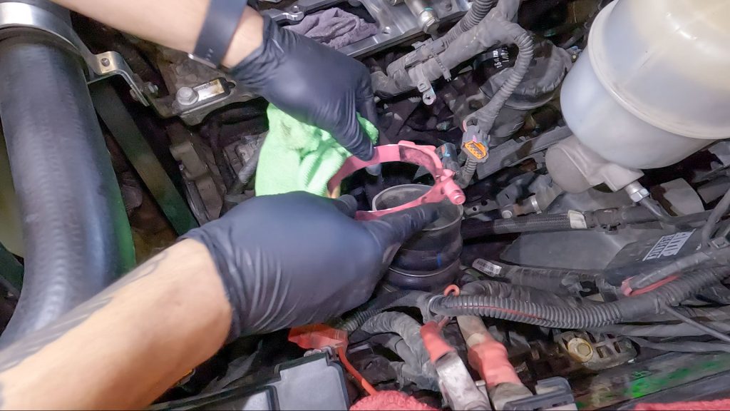
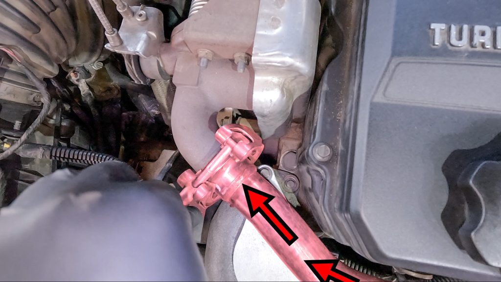
29. Loosen Boost Tube Clamp
This does not have to be fully removed, just release tension on the hose
30. Pry Boost Tube Hose Off Throttle Body
The hose may feel stuck or glued to the throttle body; carefully walk a panel popper tool around the tube to loosen its grip on the throttle body. This will make removal later on easier.
31. Remove Cable Tie Back of Elbow & Unplug MAP sensor
32. Remove Forward PCV Hose
33. Remove 6 Bolts on Elbow
34. Lean Elbow Toward You & Dislodge Boost Tube
35. Remove Throttle Control Plug
Now that the elbow has been leaned forward, you can easily reach this plug.
Slide tab over and depress the end to remove the plug.
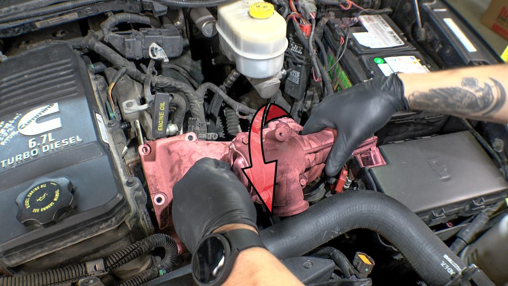
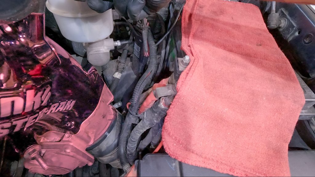
36. Place Rag & Clamp Over Boost Tube
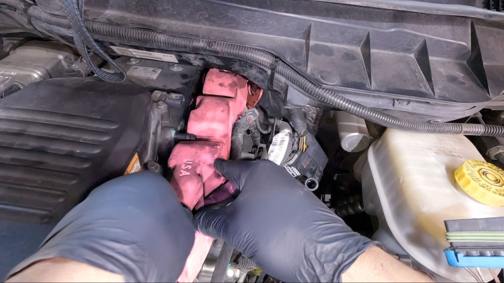
Factory Heater Plate Removal
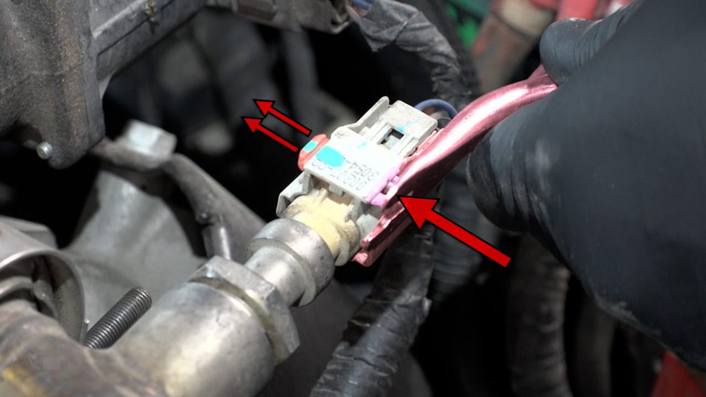
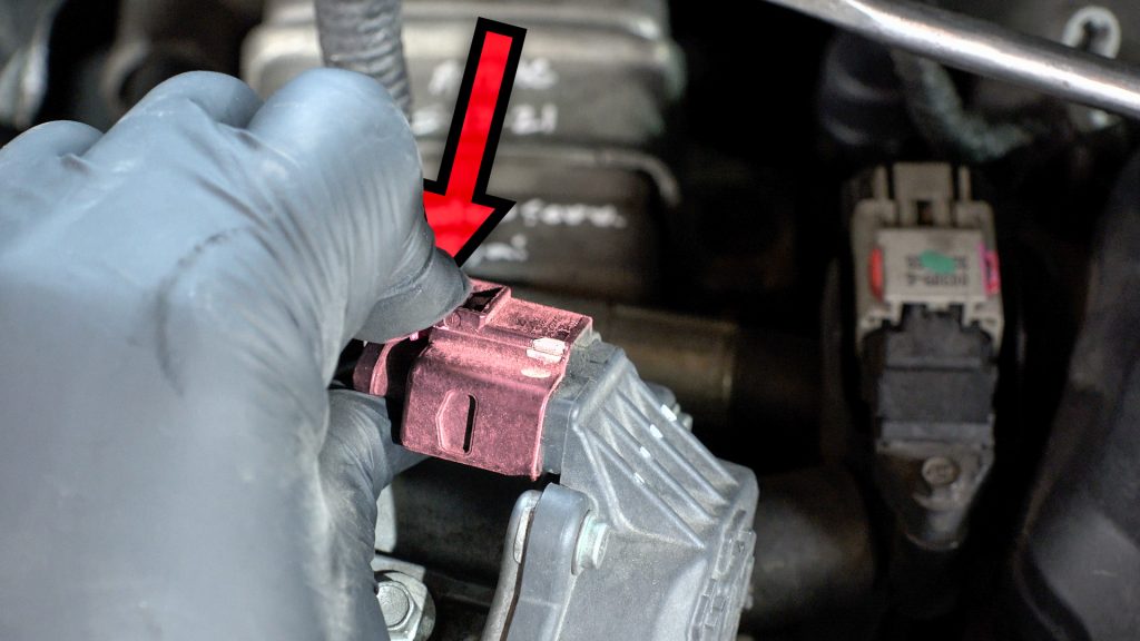
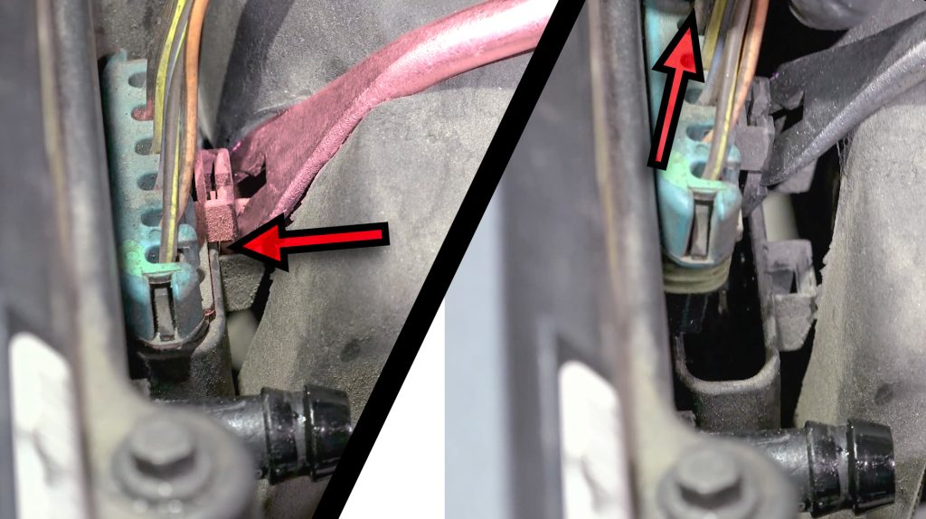
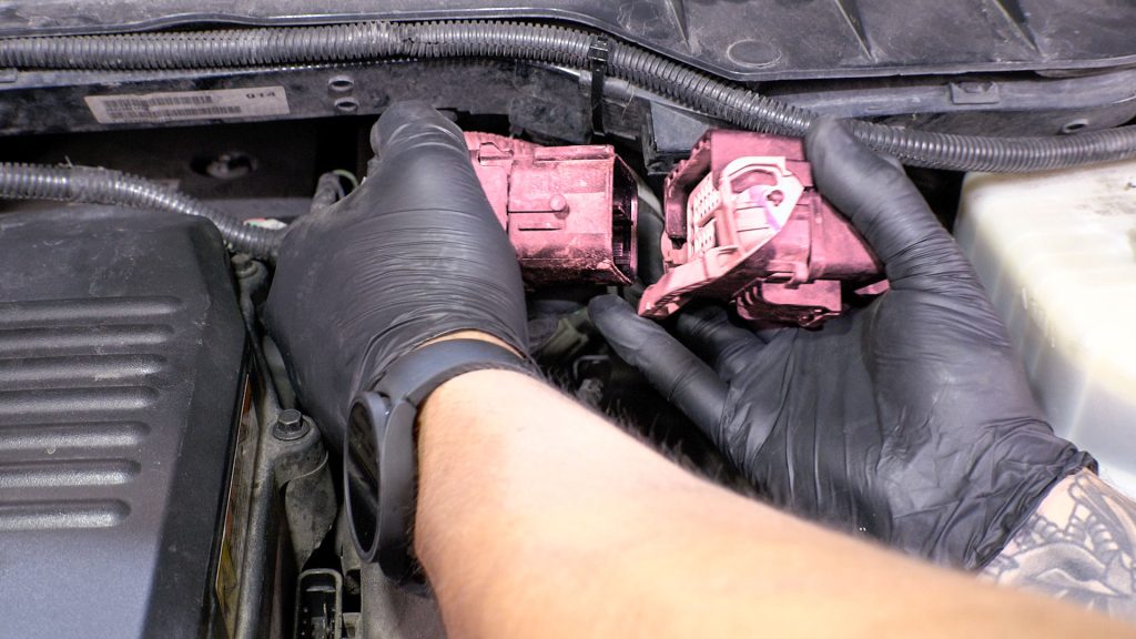
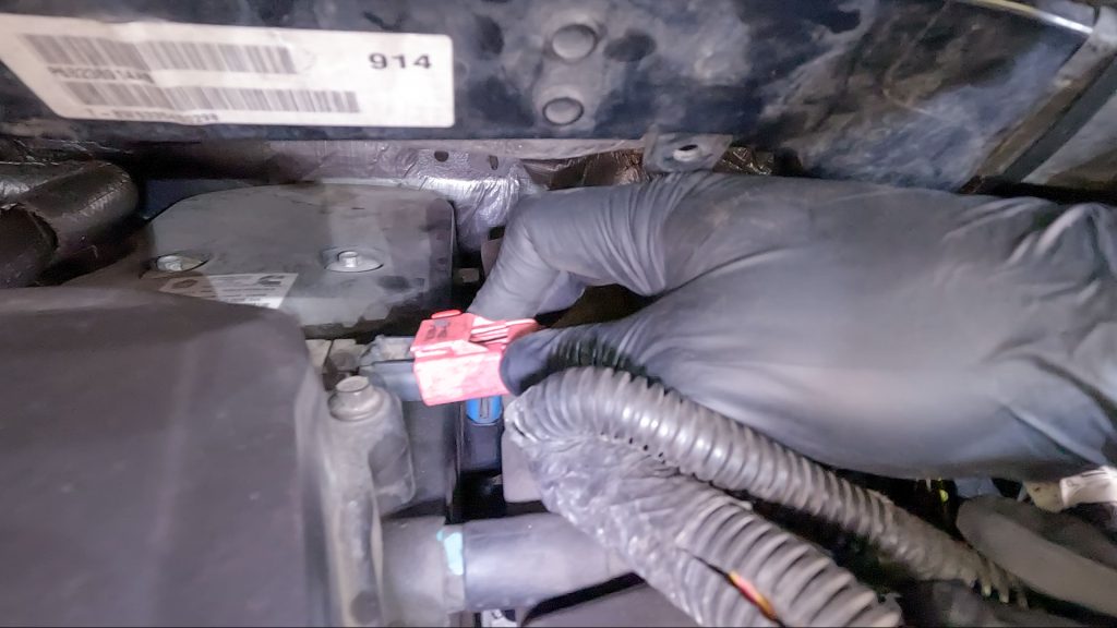
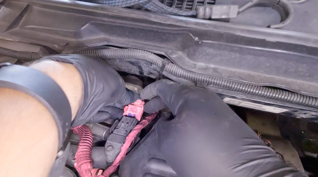
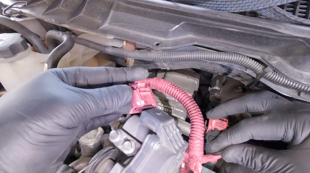
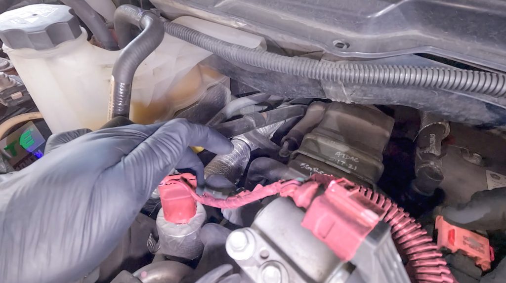
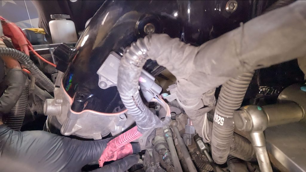
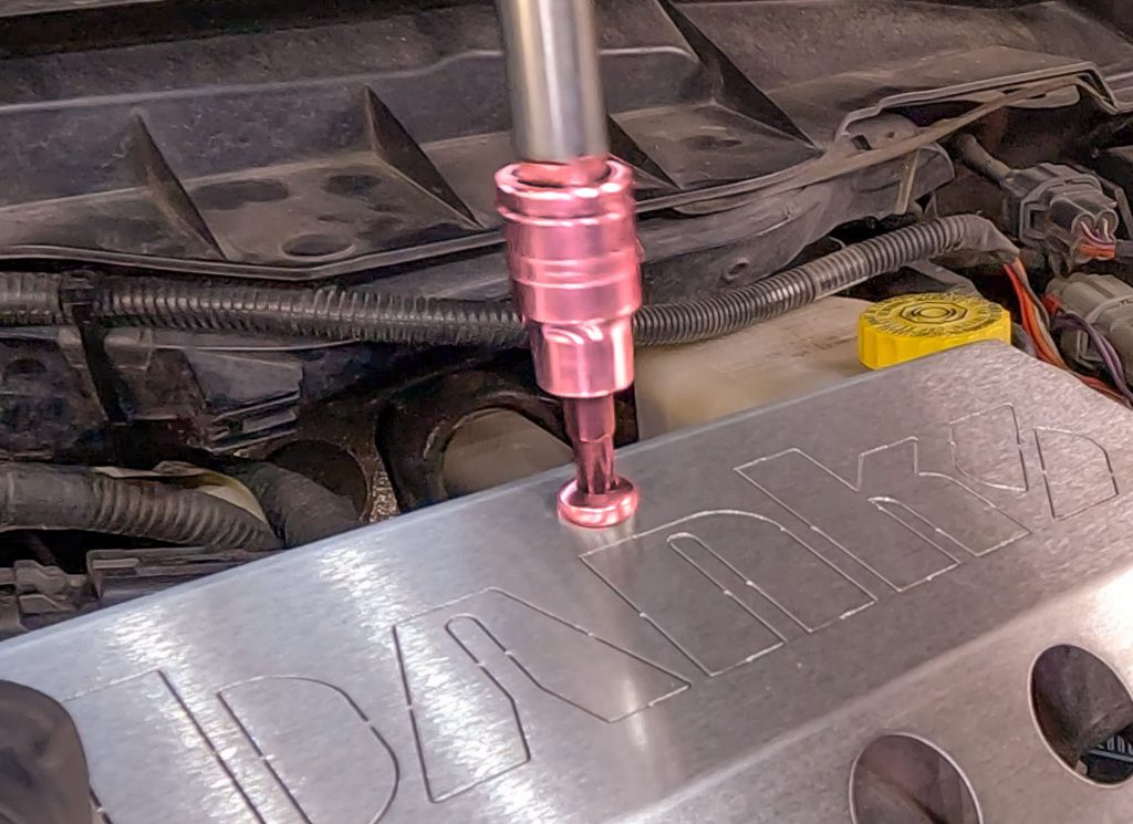
37. Disconnect First Passenger Side Plug
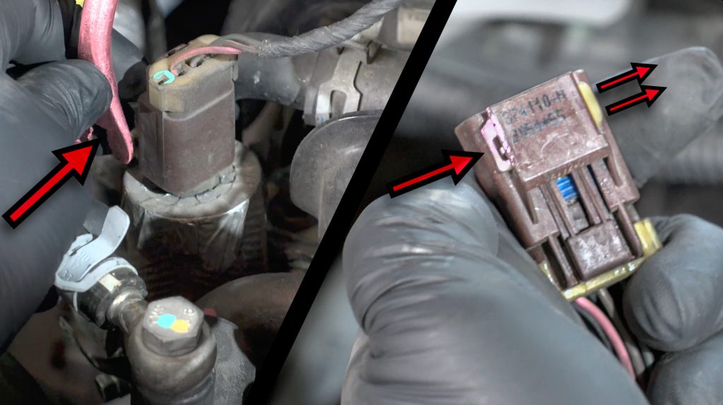
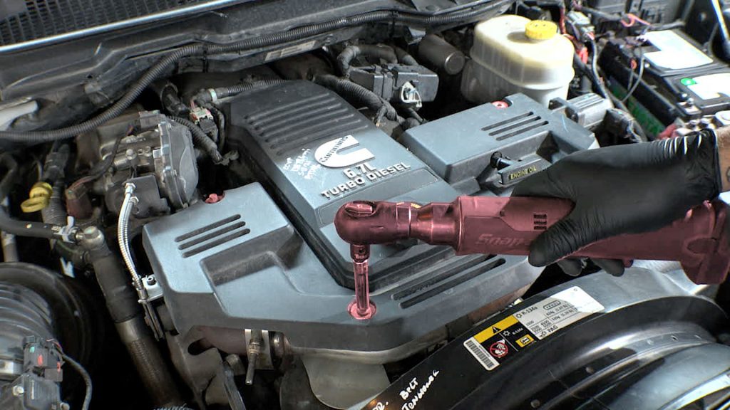
38. Slide the pink locking tab over, then pull to release
39. Disconnect Second Passenger Side Plug
Slide Lock In
Depress button to release clip
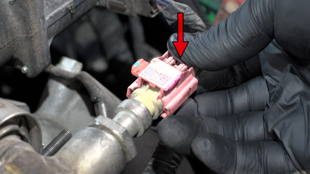
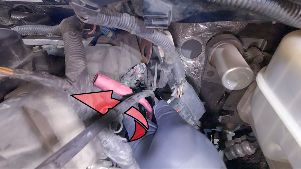
40. Disconnect Third Passenger Side Plug
41. Disconnect Third Passenger Side Plug
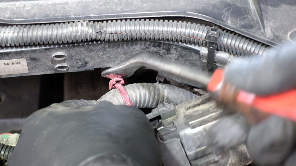
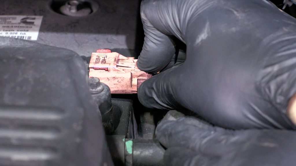
42. Locate Flat Blue Driver Side Plug
43. Press in the clip with a flat tool, and pull up.
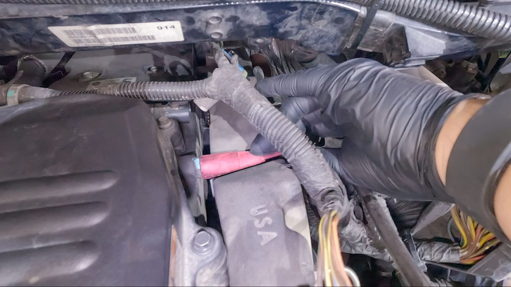
44. Disconnect Large Driver Side Engine Harness
Depress clip and fully rotate the white lock, then pull to disengage. May need some force due to dust, grime, etc.
Release cable tie
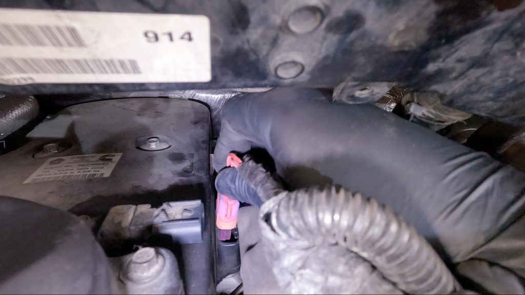
45. Remove Rear Driver Side Plug
46. Remove Rear Driver Side Flat Blue Plug
47. Remove Rear PCV Hose
48. Remove Rubber Isolator
49. Remove Cable Ties from Driver Side Studs
50. Remove Dipstick Tube Stud
51. Bungee Cord The Dipstick Tube
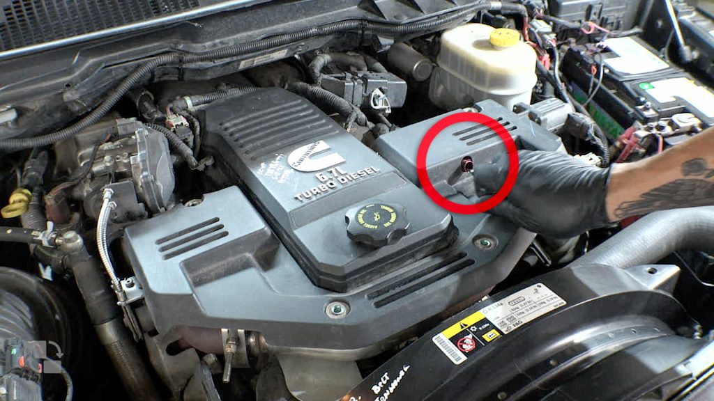
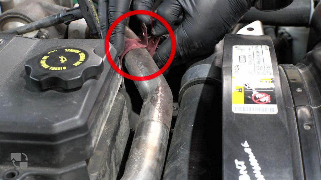
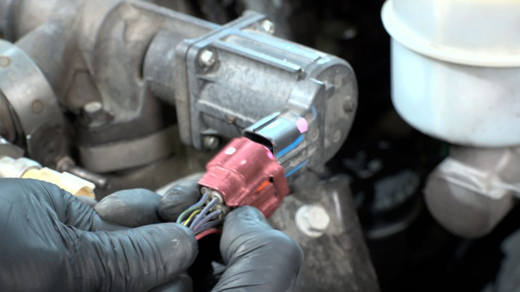
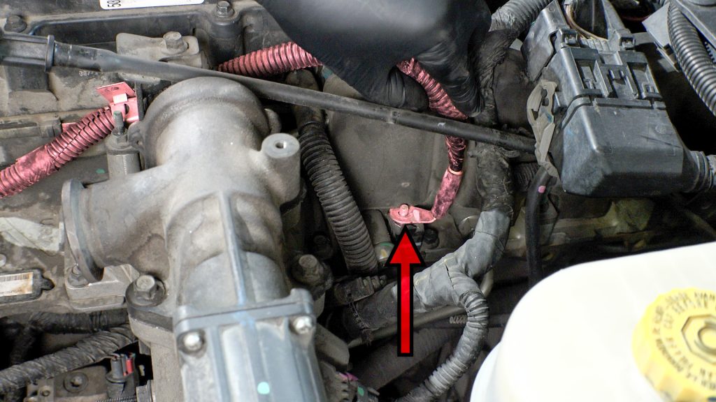
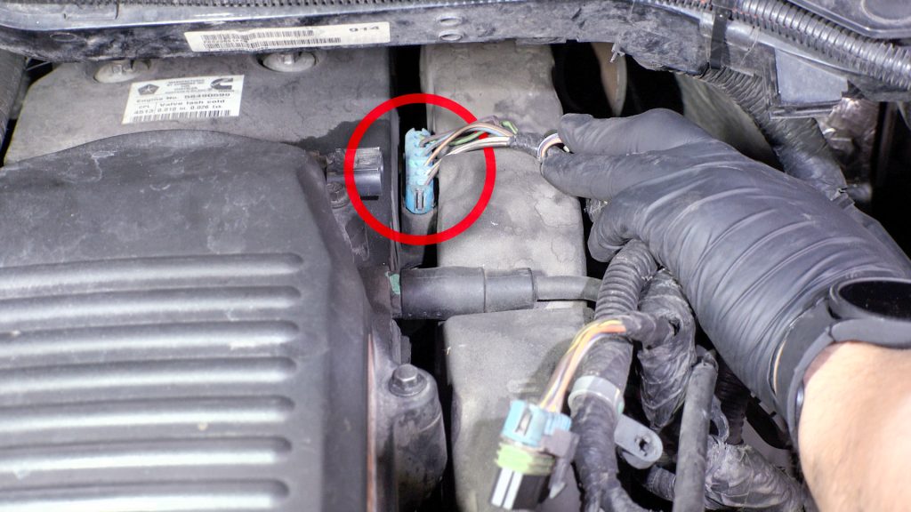
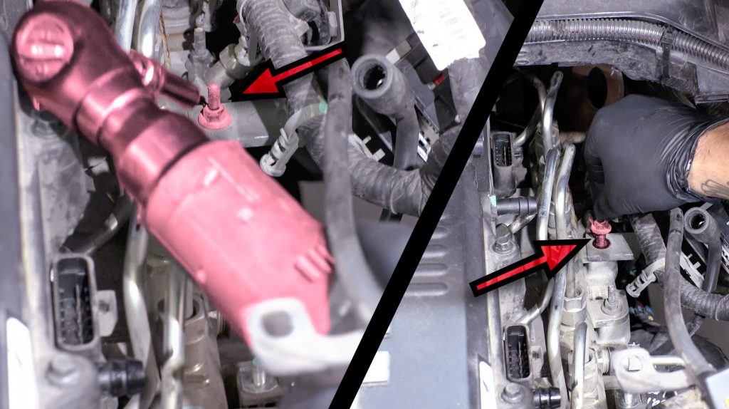
52. Remove Manifold Temp Sensor Plugs
Chassis Cab: Depending on the vehicle production date or GVWR, an EGR and/or MAP sensor may be mounted on the rear of the intake manifold plate.
Chassis-Cab: MAP Sensor
The Chassis-Cab MAP sensor is located on the rear of the intake manifold.
This sensor will be transferred to the MAP sensor provision on the Banks Monster-Ram later in your install.
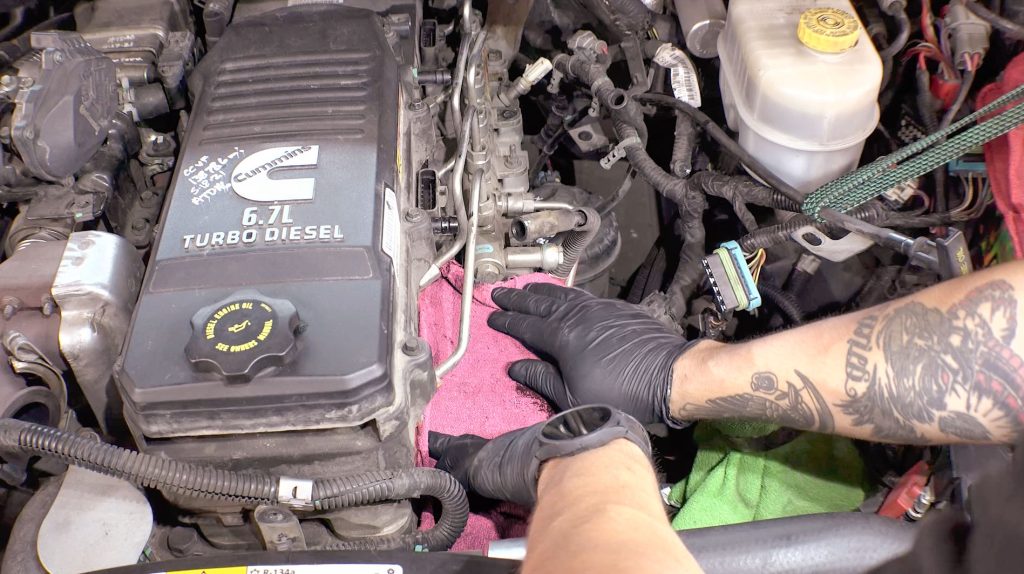
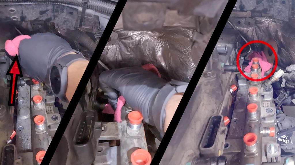
53. Place Rag Over Intake
54. Remove Fuel Lines
If the inserts in the head start to move, use an open ended wrench to hold them inlace.
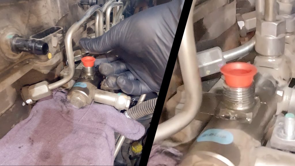
55. Install Dust Covers
Insert the covers, open end facing out. The caps should fit (inside) each blocked port.
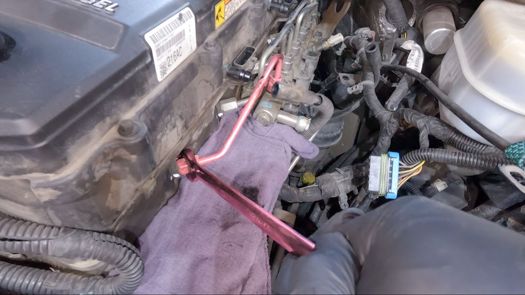
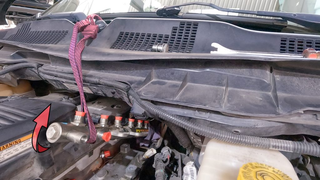
56. Loosen #6 Fuel Line & Rotate Out of Way
Do not fully remove the rear fuel rail. It is difficult to reach and only needs to be moved out of the way as shown.
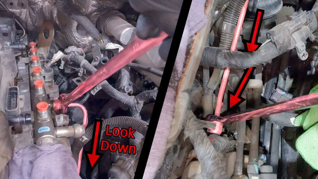
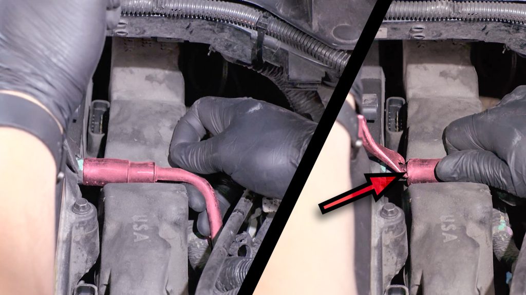
57. Loosen High Pressure Fuel Feed Line
Both the upper and lower ends.
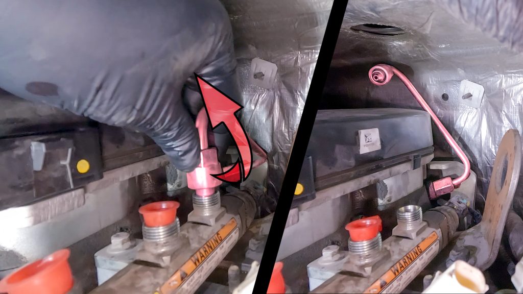
58. Swivel Back High Pressure Fuel Feed Line
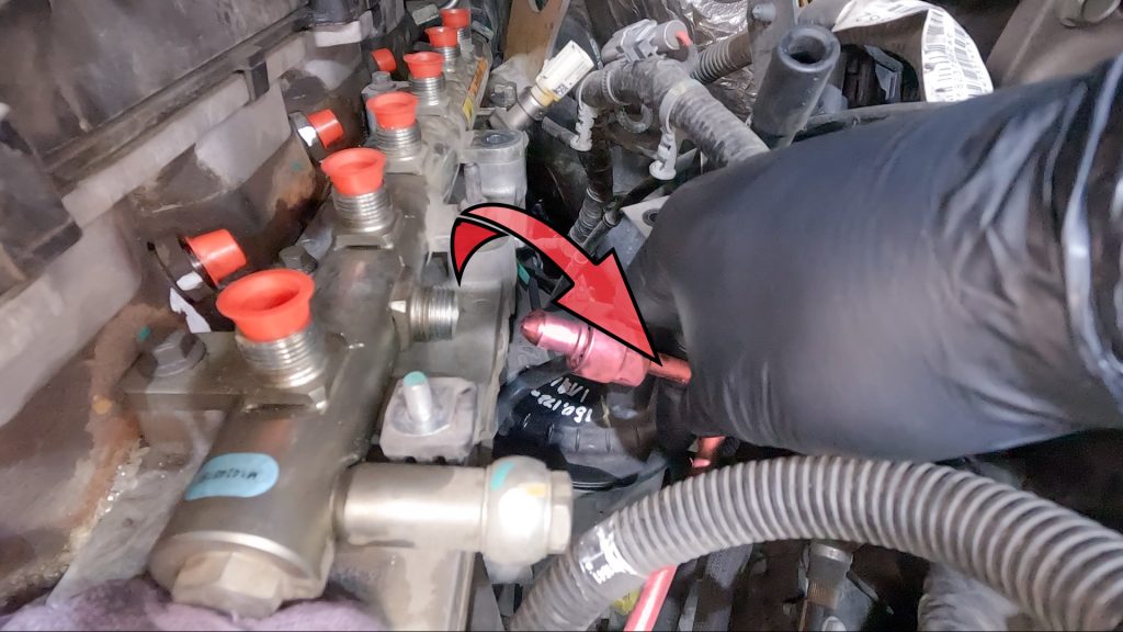
59. Remove Banjo Bolt
Take care not to lose the washer between the fuel rail & banjo bolt.
60. Remove Fuel Rail Bolts
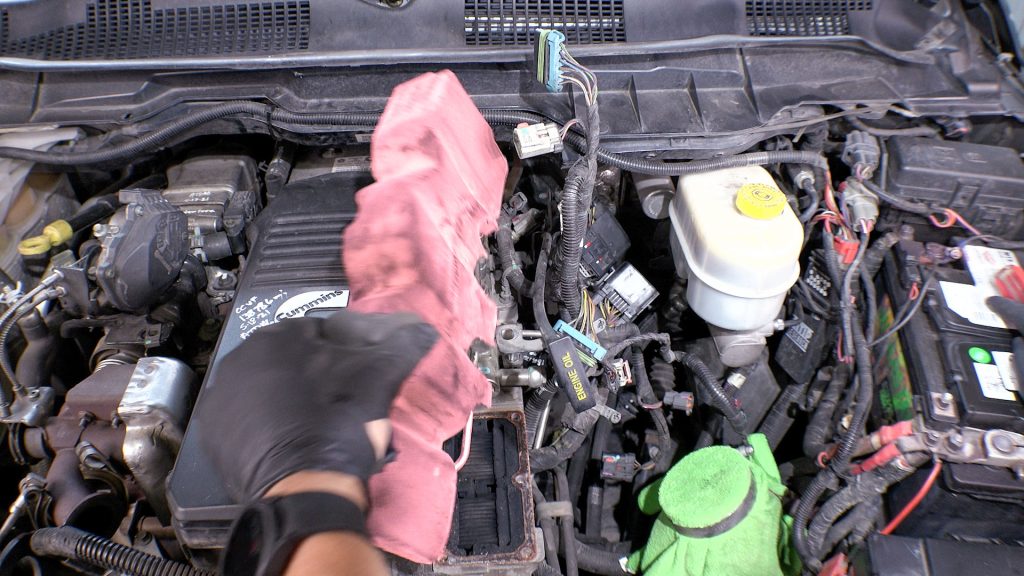
61. Place Rag At The Rear of Fuel Rail
There will still be fuel in the rail, and it’ll leak out in the next step if you don’t do this.
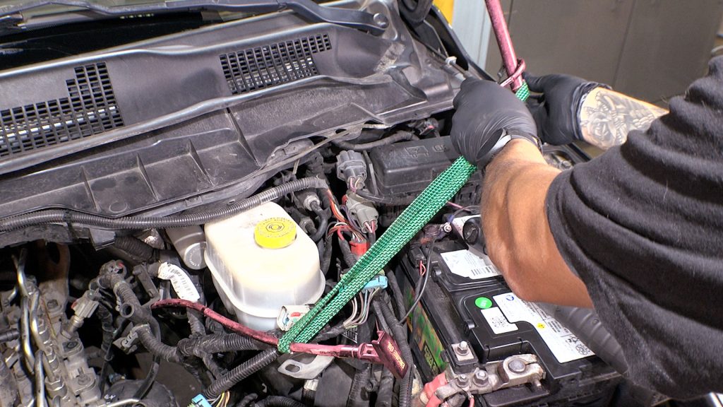
62. Bungee Fuel Rail
Be sure that rag stays at the rear of the fuel rail, it will leak when you tilt it back.
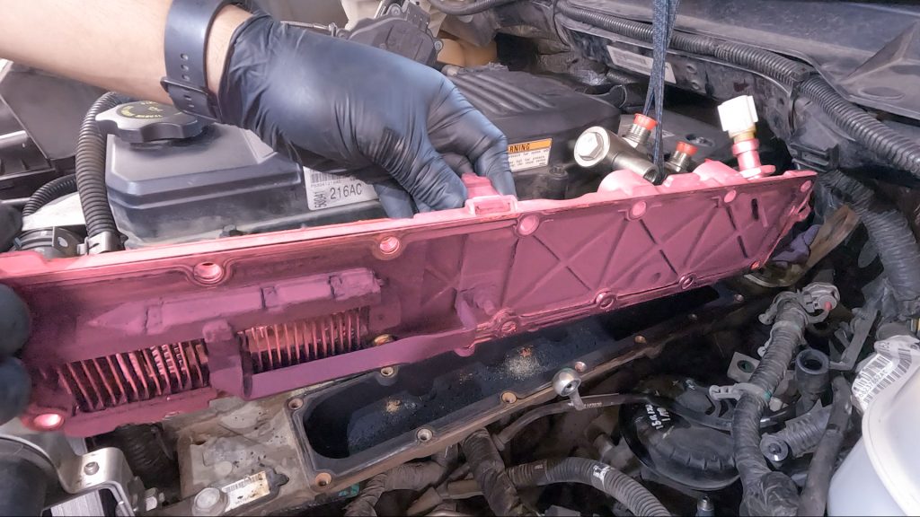
63. Remove Factory Grid Heater
64. Clean Manifold Surface
Take care not to scratch the surface, and vacuum out any debris that fall into the manifold.
A rag with some solvent can clean up the finer material.
Be certain there is no rust buildup. Rust or an uneven surface will result in an air leak.
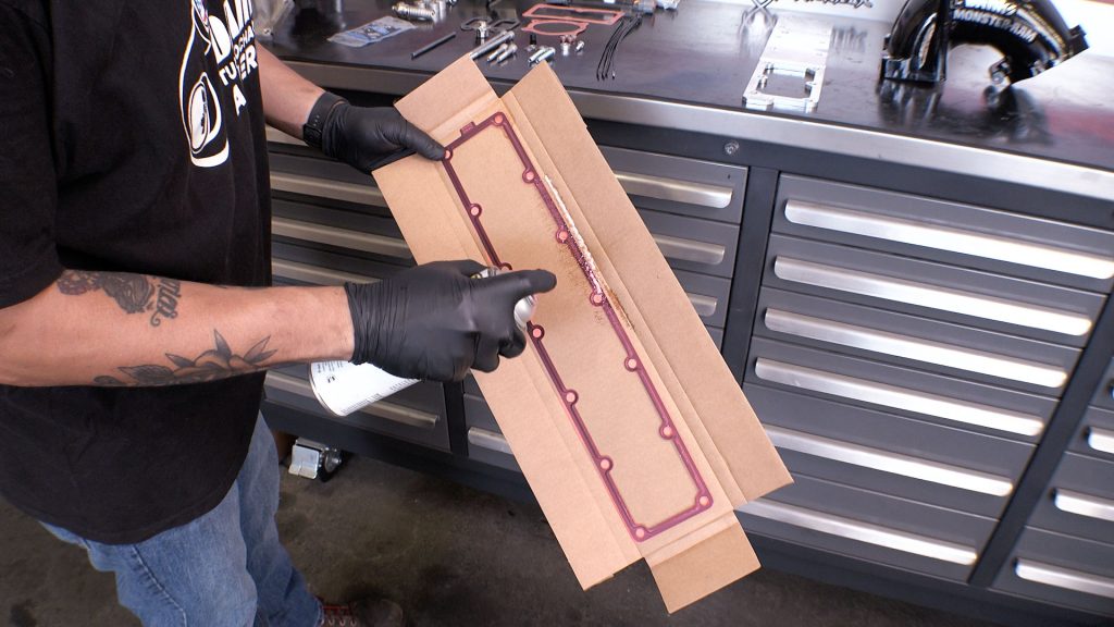
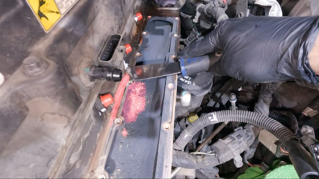
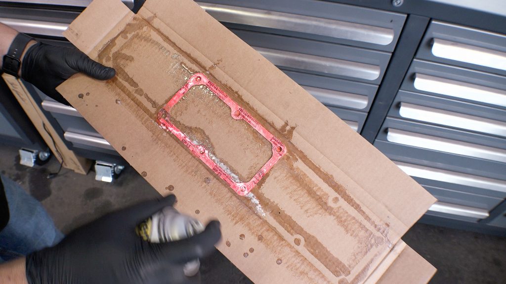
65. Spray Adhesive to Gasket (Banks Side)
Side that says Banks, should be the side with the adhesive. Let it sit for about 3 min for the glue to tack up.
66. Align Gasket & Stick On
Line up all of the bolt holes, and stick the gasket to the flat side of the billet plate.
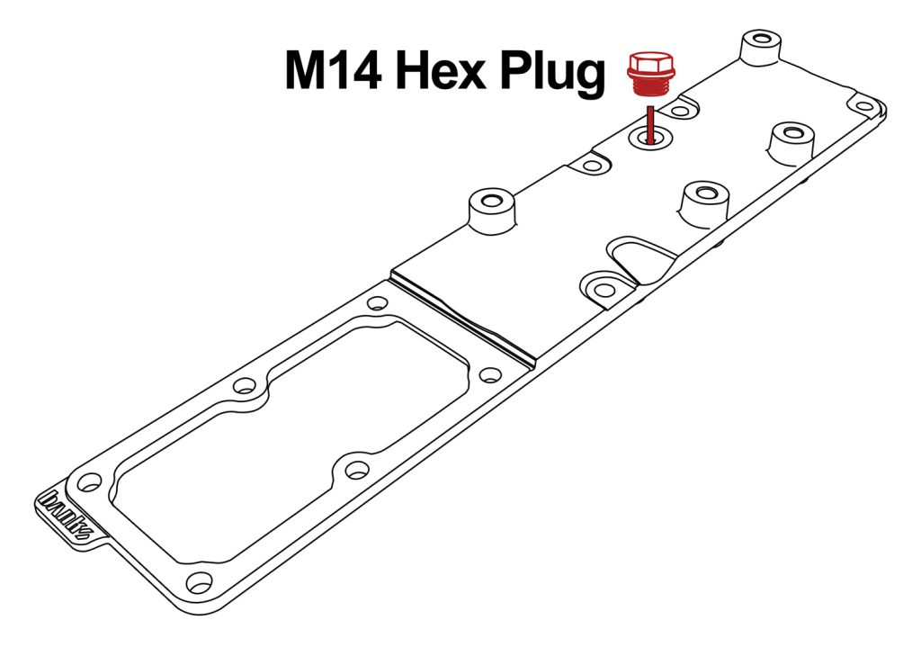
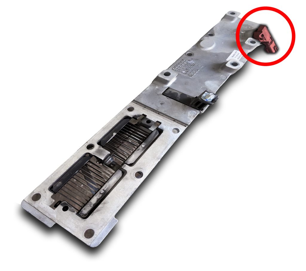
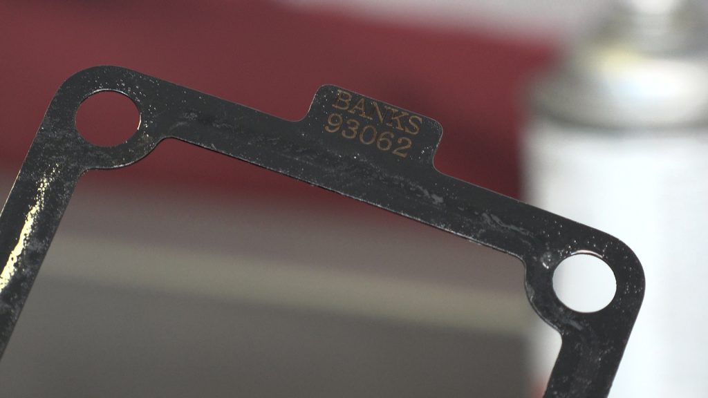
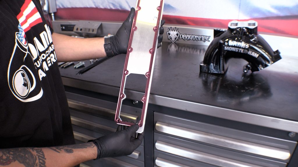
67. Note: M14 Plug (62248)
Chassis Cab: Depending on the vehicle production date or GVWR a thermocouple temp sensor may be mounted on the Manifold Plate.
If your vehicle was equipped this way, transfer the sensor into the Banks Billet Plate.
If your vehicle was not equipped this way. Plug the Billet Plate with the M14 Plug.
Don’t over-tighten into the billet plate as the aluminum is softer than the steel threads. It will bottom out so you’ll know when to stop.
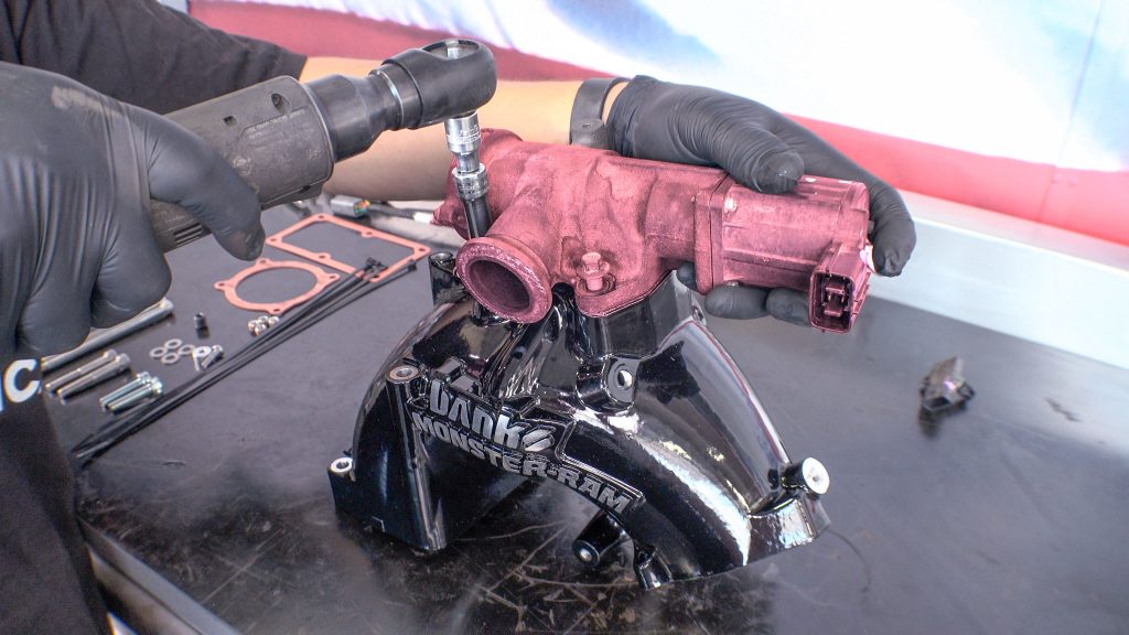
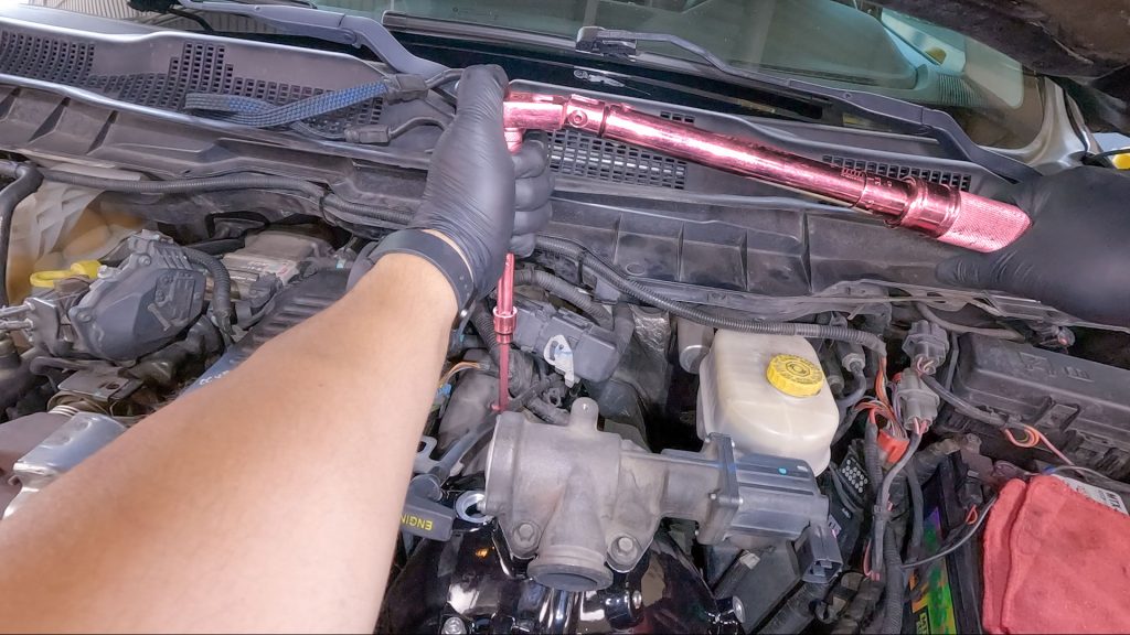
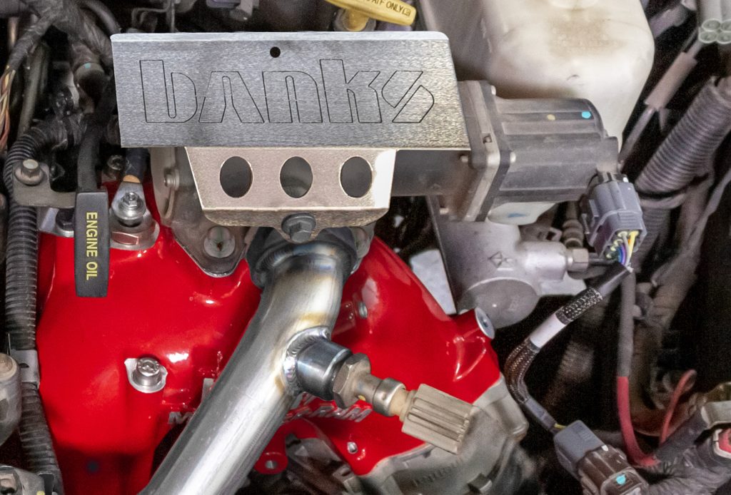
Installation of Monster-Ram
68. Remove EGR Valve
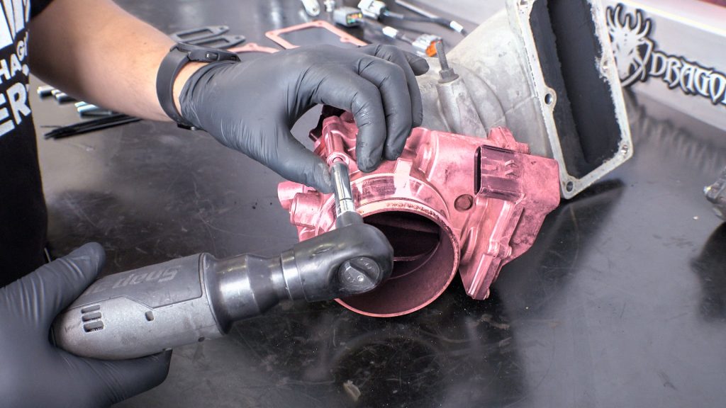
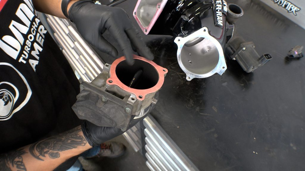
69. Remove Throttle Body
The throttle will be stuck onto the gasket, so use a rubber mallet to help tap it free from the elbow.
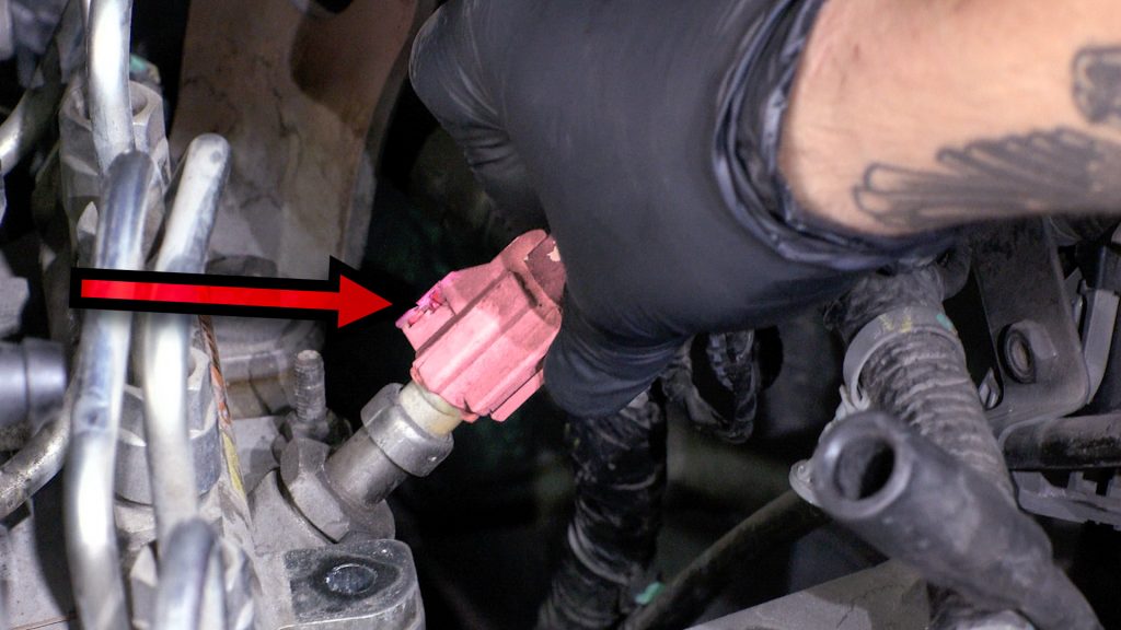
70. Remove & Transfer MAP Sensor
The Chassis-Cab MAP sensor is located on the rear of the intake manifold.
Transfer the MAP sensor from the rear of the intake manifold plate, to the back side of the Banks Monster-Ram.
You will use the MAP-Extension Harness included in your kit to re-connect the sensor.
71. Remove & Transfer Elbow Stud
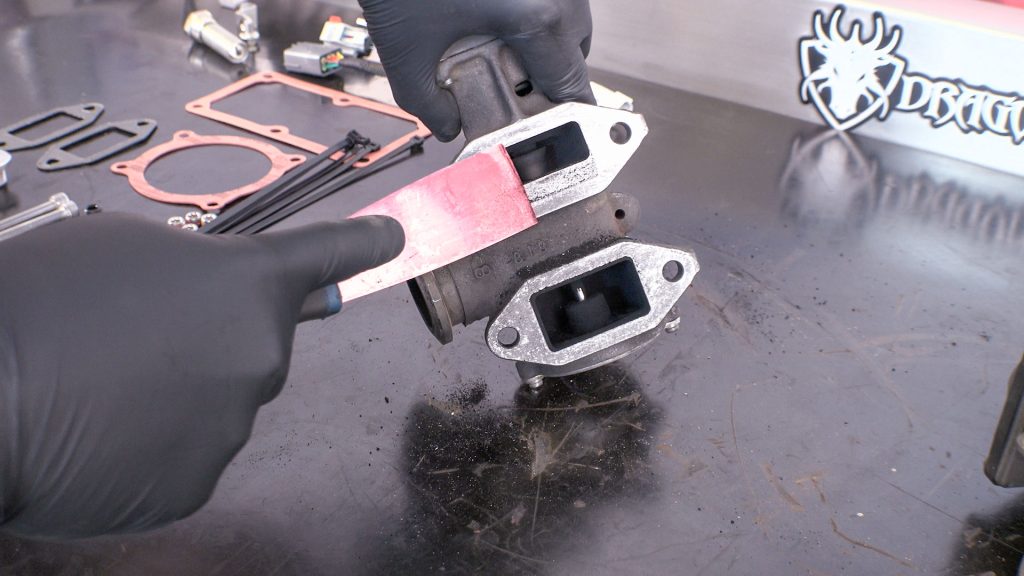
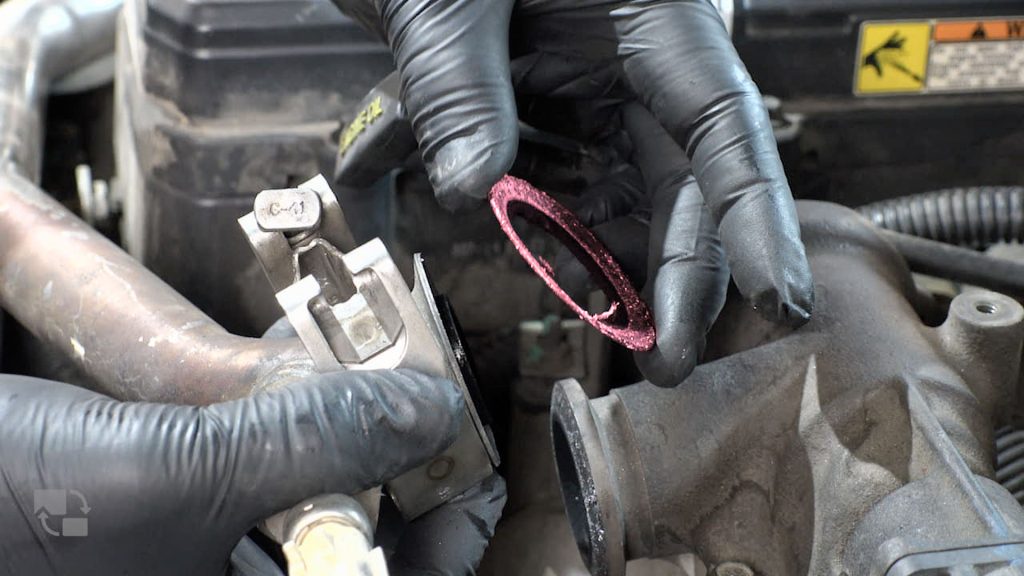
72. Clean EGR Gasket Surface
Take care not to nick the surface. Do the same for the throttle body gasket mating surface.
73. Place New EGR Gaskets On Monster-Ram
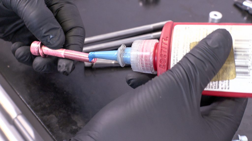
74. Fasten EGR Bolts
Apply a small amount of medium strength thread locker and tighten to 18 ft/lbs.
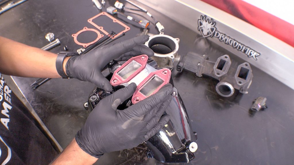
75. Align Throttle Body Gasket
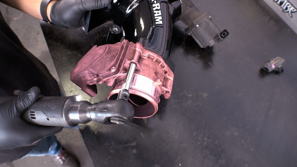
76. Fasten Throttle Body to Monster-Ram

The 1/8” NPT ports shall only be used for installing sensors for measuring air temperature, pressure, or flow. Sensors installed to these ports shall have a fitting of 1/8” NPT and shall not be connected to the vehicle’s electronic control units. In addition, factory sensors that come equipped on the vehicle shall not be disconnected and shall not be relocated to the ports. The ports, when not used, shall be closed off with the supplied plugs.
77. Install Sensor Plugs
Inspect the threaded holes, and be sure there is no powder coat in the holes.

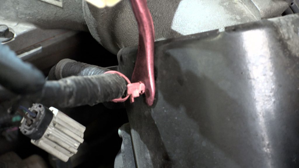
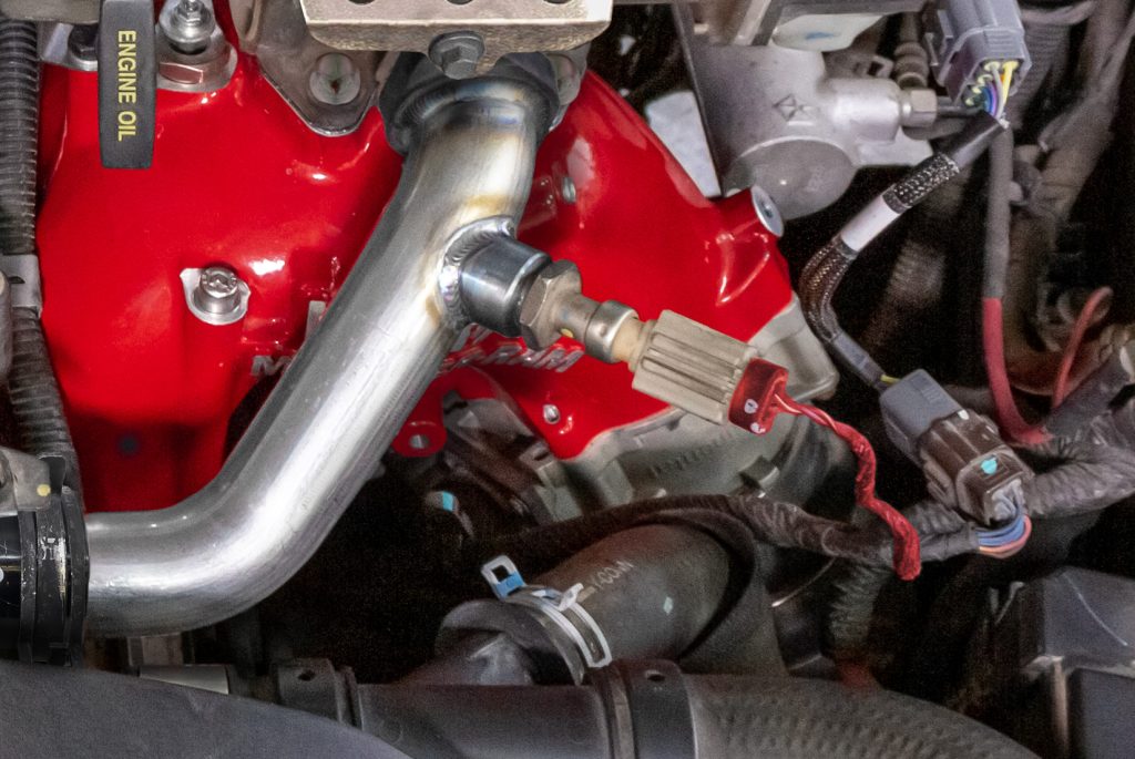
78. Rear Temp Sensor.
Chassis Cab: Depending on the vehicle production date or GVWR your EGR temp sensor may be mounted on the rear of the Monster-Ram.
If your vehicle was not equipped this way. Plug the rear EGR port with the M12 Plug and apply a 360° bead of blue Loctite around the leading threads first.
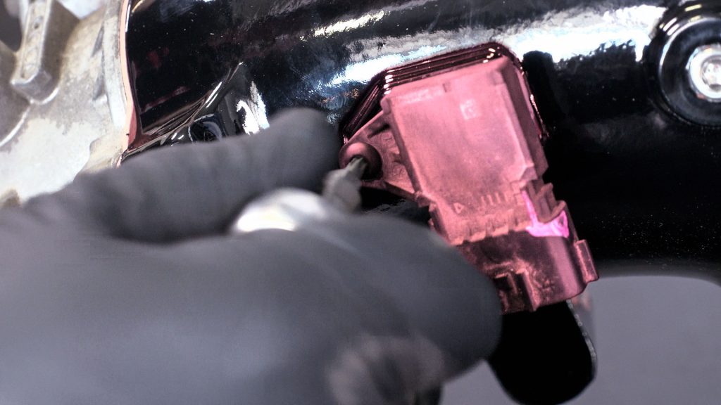
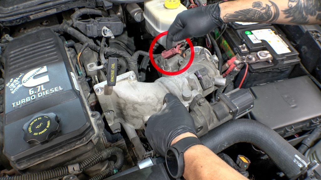
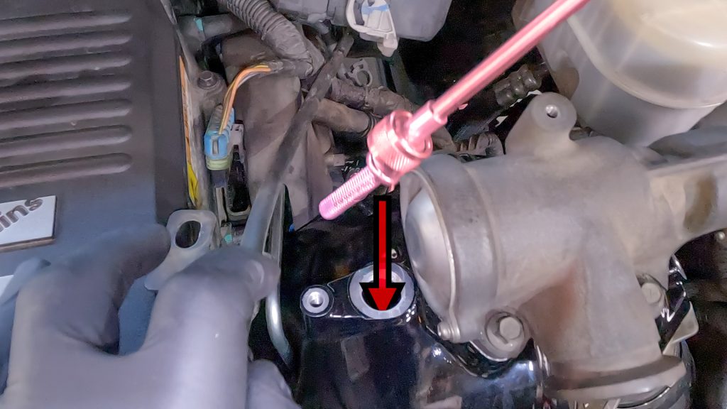
79. Install MAP Sensor
Now is a good time to clean the sensor with some MAF/MAP cleaner spray.
80. Spray Gasket With Adhesive
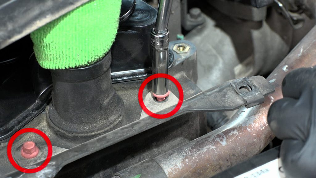
81. Place Washers On The Hex Cap Screws, Then Apply Some Blue Threadlocker As You Install Them
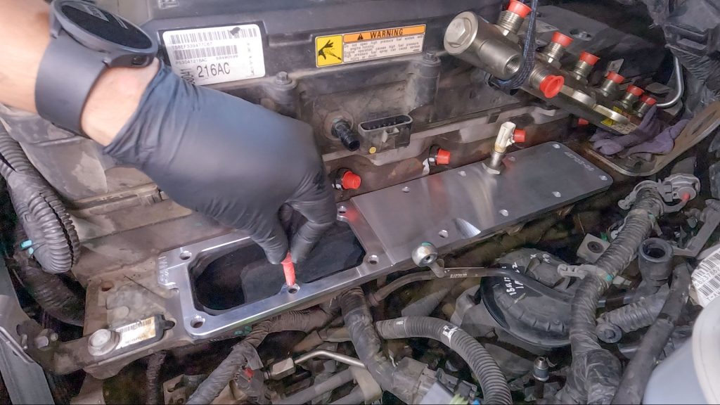
82. Use a Stock Bolt to Hold Billet Plate in Place
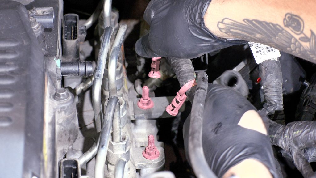
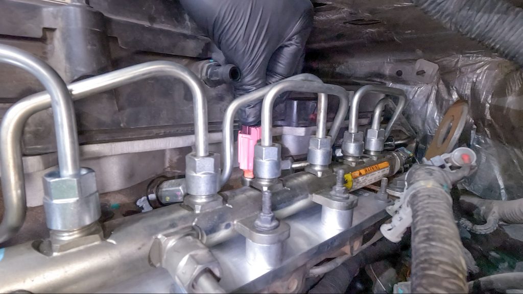
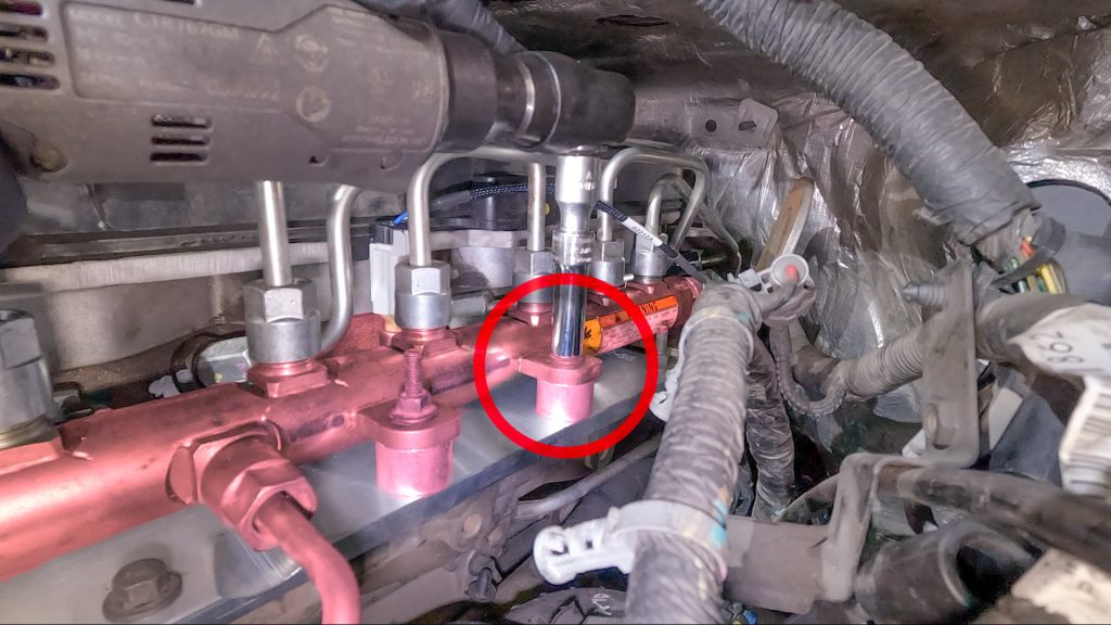
83. Place Fuel Rail Standoffs
If your kit includes the cast aluminum plate (42731), these standoffs will not be included, and this step can be skipped.
84. Release Bungee Cord. Place Fuel Rail & Studs in Place
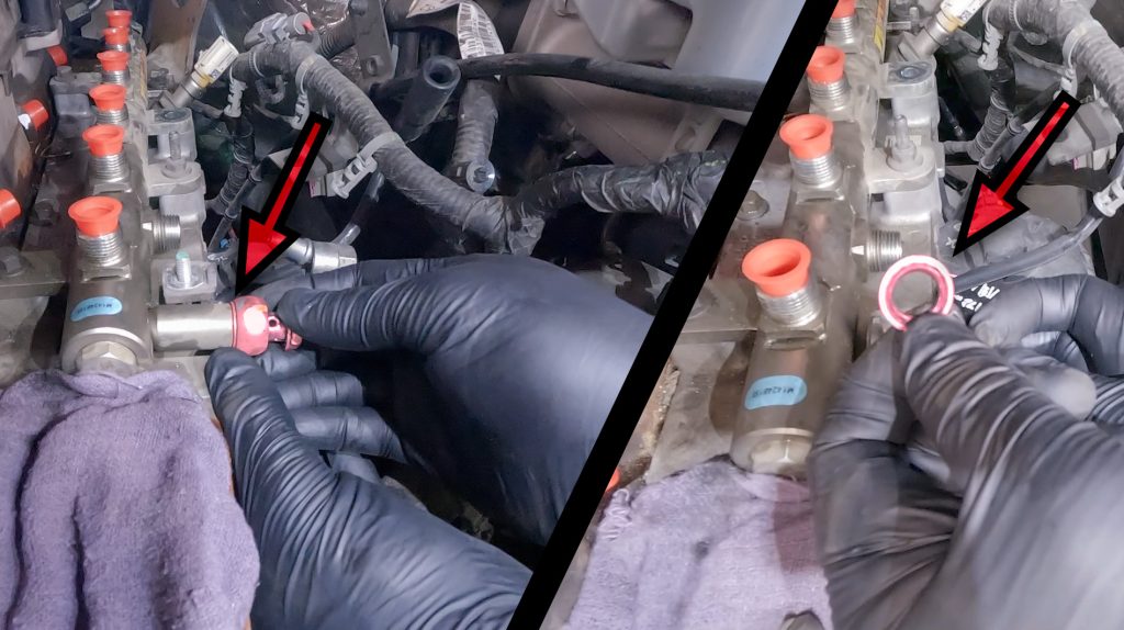
85. Install Banjo Bolt & Washer
86. Tighten Fuel Rail
Torque Bolts to 18-20 ft/lbs
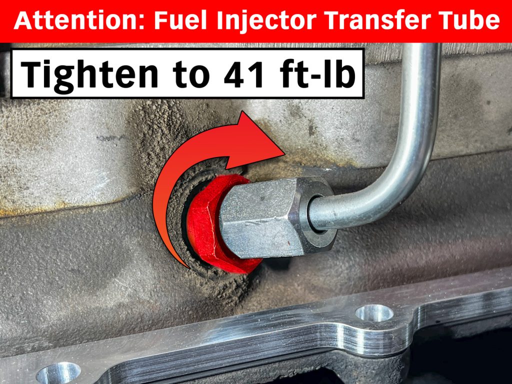
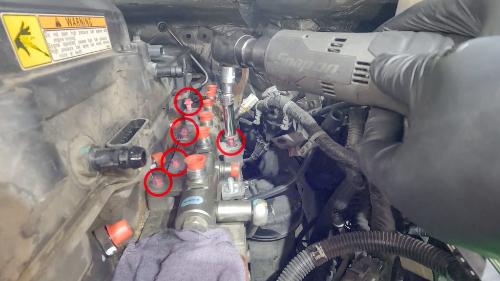
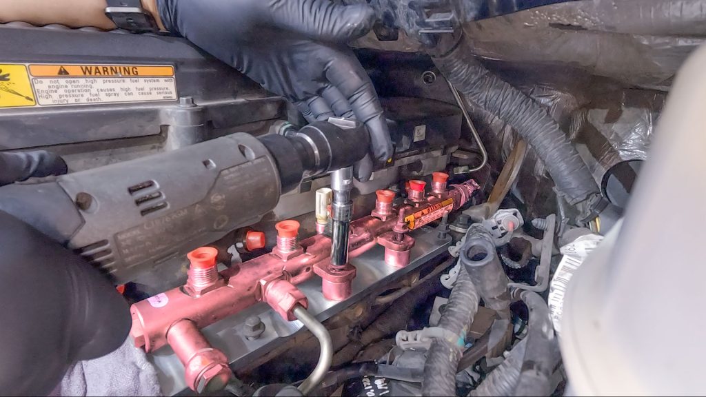
Attention:
Due to age and vibration, over time the fuel injector transfer tube that the fuel lines thread into can back out and loosen.
Check that each of the 6 transfer tubes are torqued to 41 ft/lb before reinstalling the fuel lines.
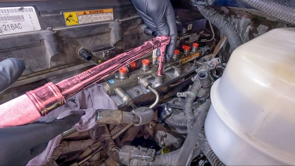
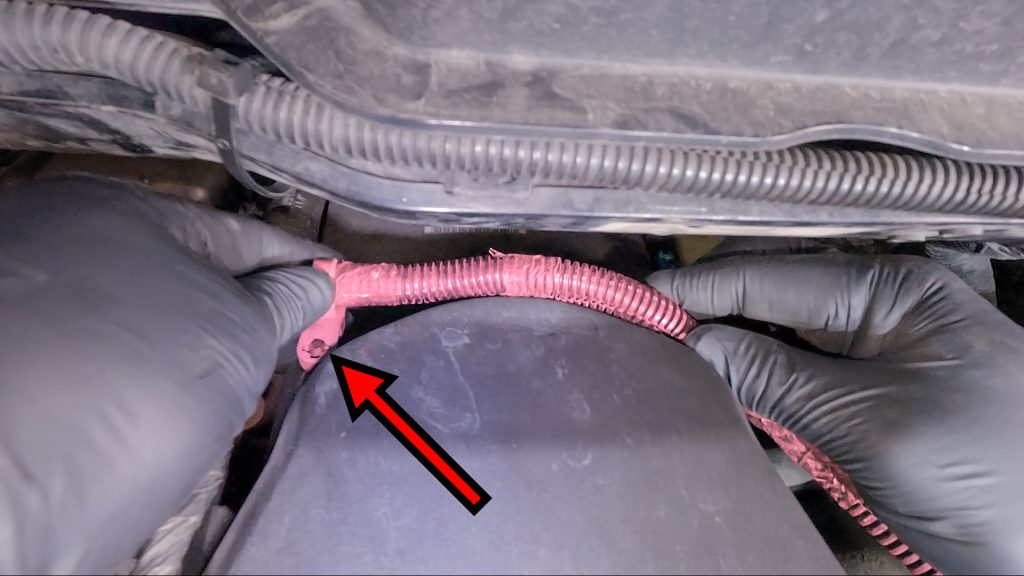
87. Tighten Fuel Lines to 30 ft/lbs
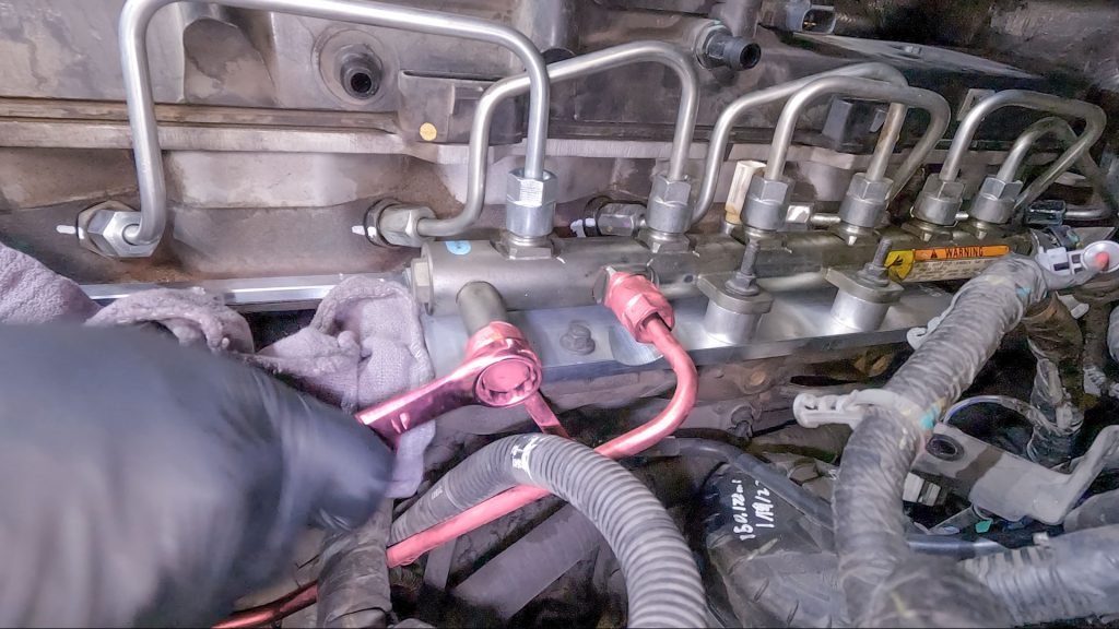
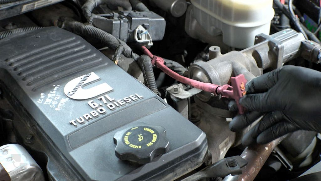
88. Tighten Fuel Supply Line Banjo Bolt Hand Tight & Fuel Feed Line To 30ft/lb
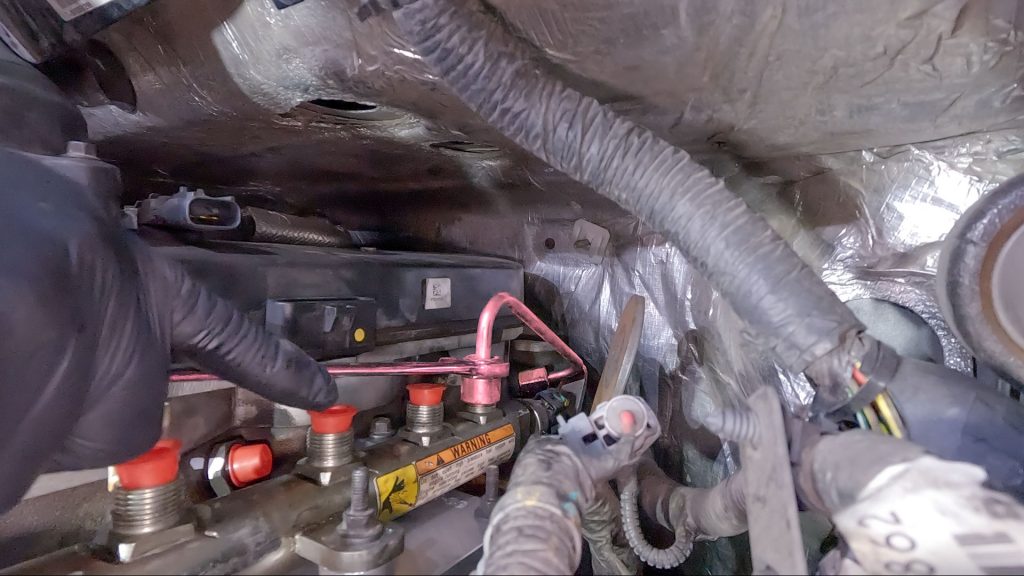
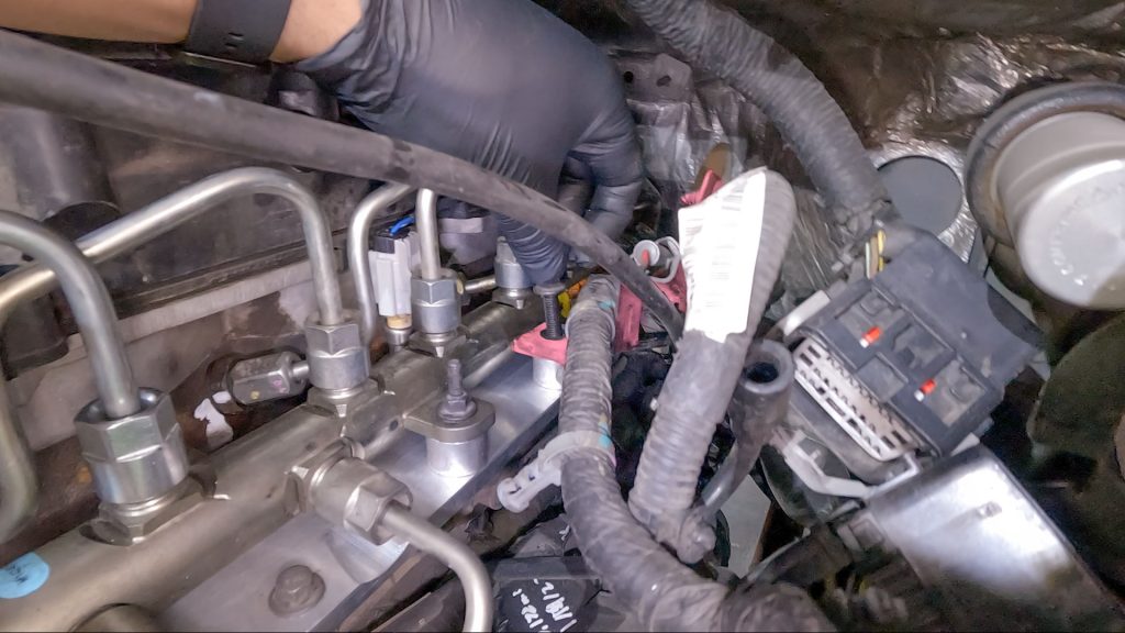
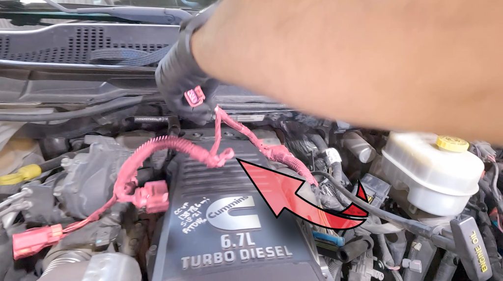
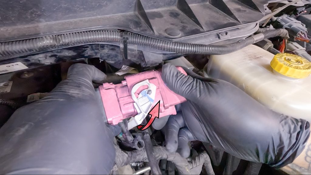
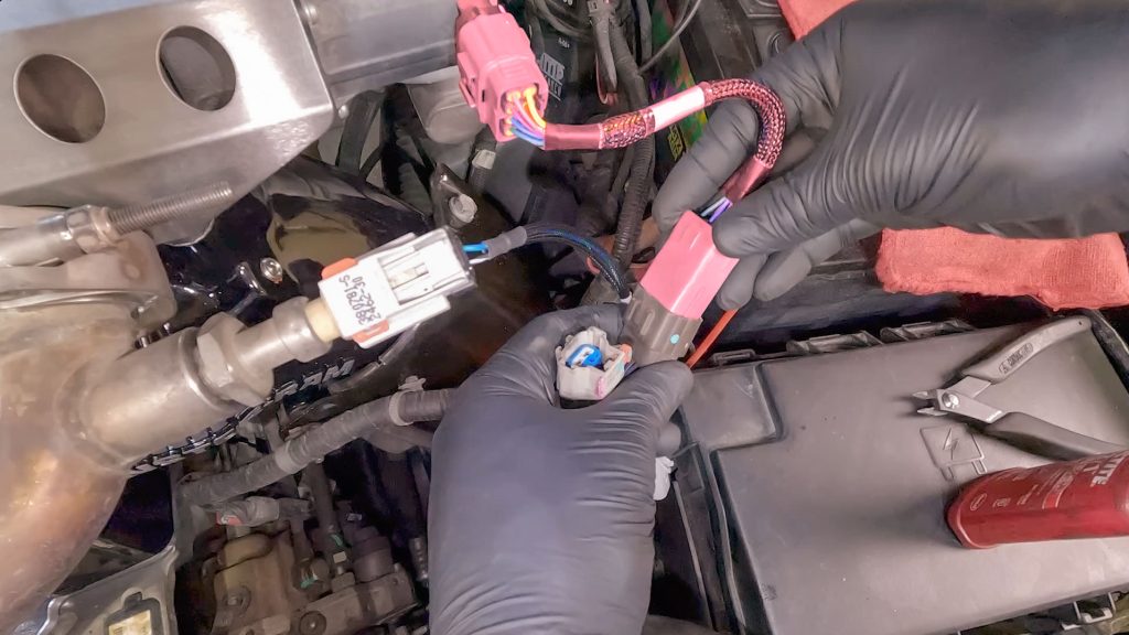
89. Connect Temp Sensor Extension Harness.
Be sure to lock the plug once connected.
90. Remove Middle Right Stud For Dipstick Tube
Slide Dipstick Bracket Over & Reinstall Stud
91. Push Engine Harness Cable Ties Back Onto Studs
92. Put Rubber Isolator Back Into Place
93. Run Rear PCV Hose Under Dipstick Tube
94. Connect Rear PCV Hose Back To Valve Cover
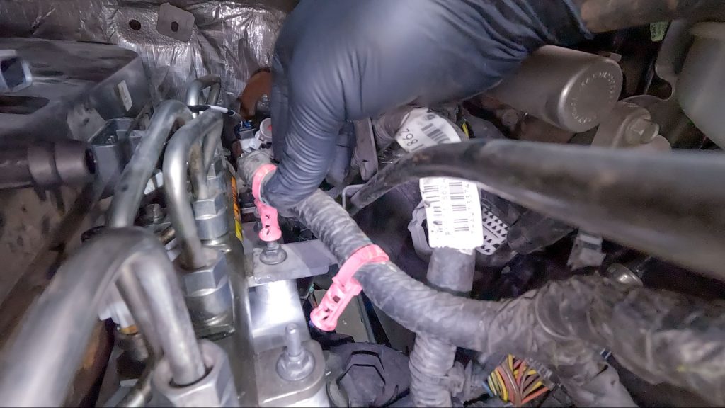
95. Connect Rear Flat Blue Injector Plug
96. Connect Rear White Plug
Be sure to slide the pink lock back into position.
97. Route Engine Harness Under Dipstick & Around Valve Cover
97a. Plug In 3 Remaining Plugs
98. Push Cable Ties Onto Studs
99. Reconnect Engine Harness Connector
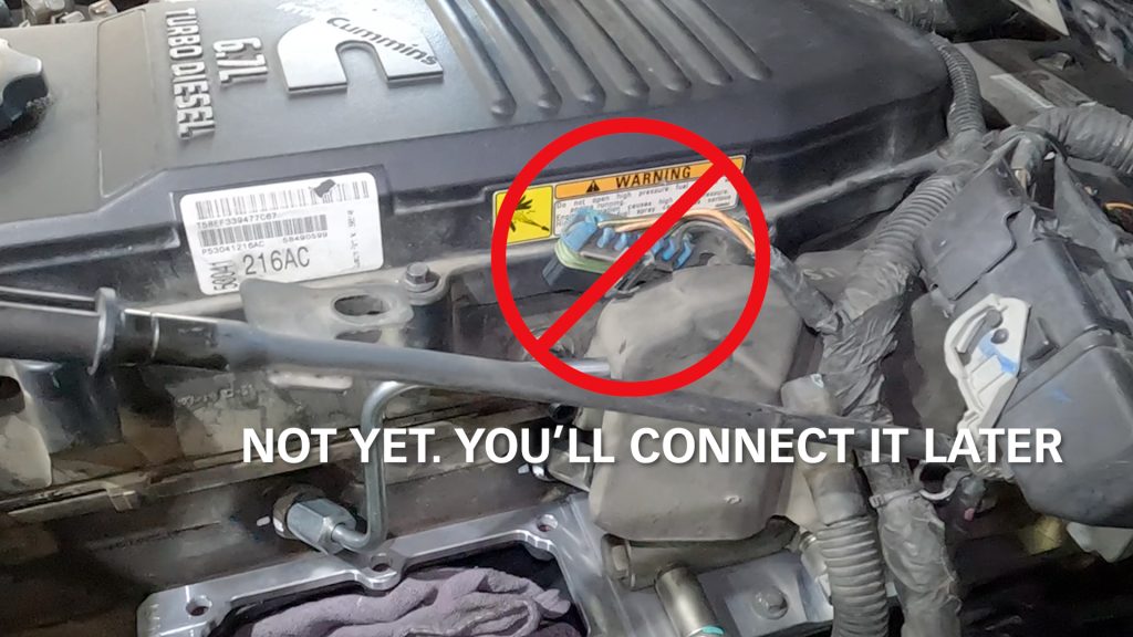
100. Do Not Connect Front Blue Injector Plug Yet
101. Remove Rag From Boost Tube, Put Clamp Back On
102. Insert Monster Ram Into Boost Tube
103. Put Long Bolt Into Front Corner by Hand
This will help hold the Monster-Ram in place. Then do the same for the long bolt on the backside. Followed by the two smaller bolts.
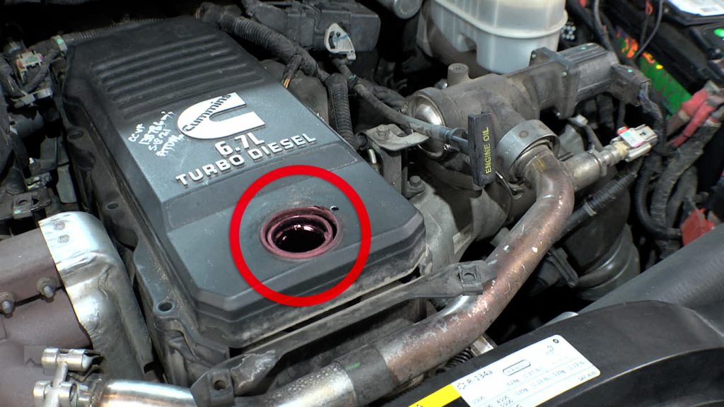
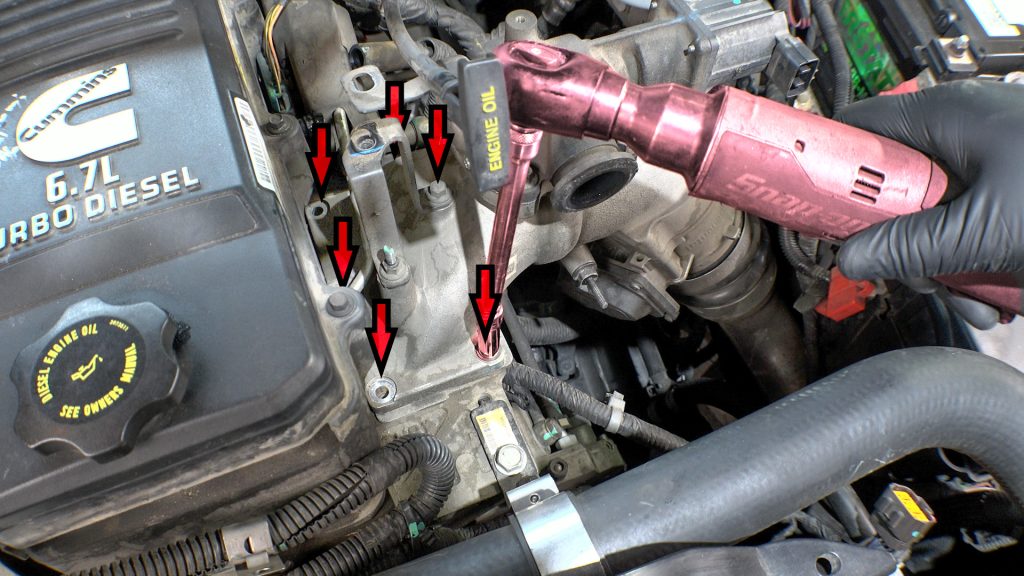
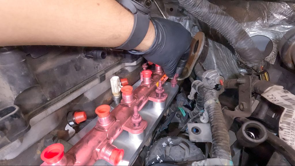
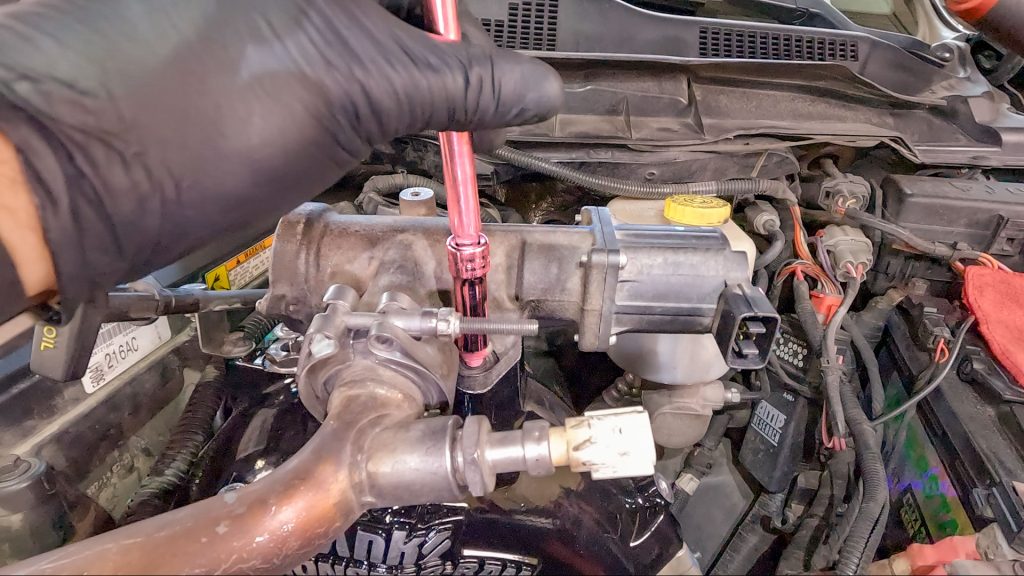
104. Use Telescoping Magnet to Start Bolts in the Middle of the Monster-Ram
This is useful for the small bolt in the middle where it is hard to reach., and mandatory for the one that goes through the top coil heater hole. Be sure to use Medium strength thread locker.
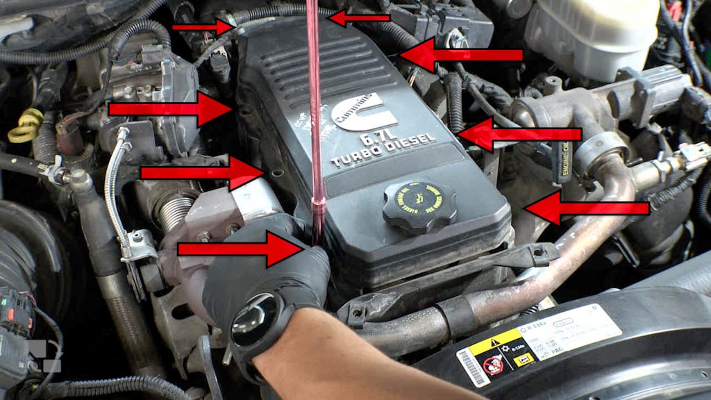
Use Hex Key Extension to Tighten Bolt
Tighten All 6 Bolts 18-20 ft/lbs
Start with the bolt that’s inside the Monster-Ram, then work in a cross pattern to torque to spec.
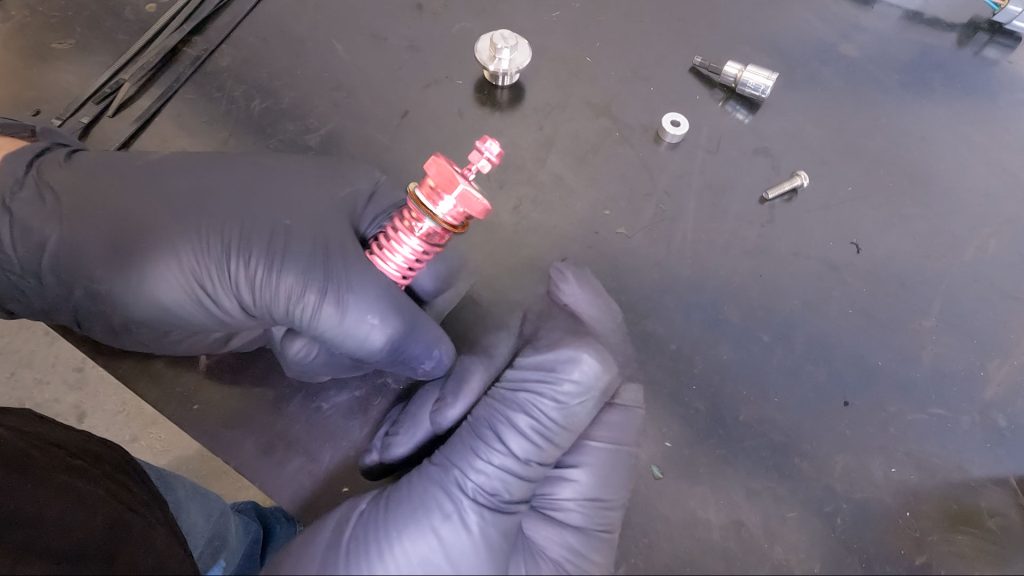
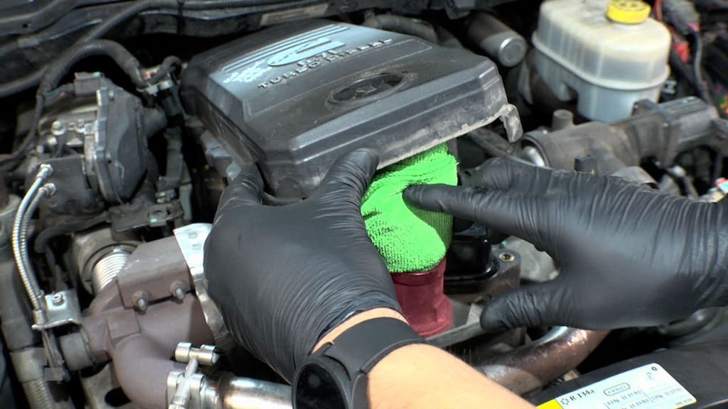
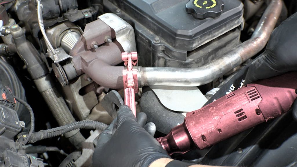
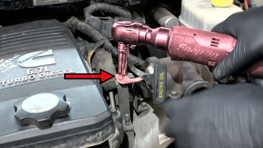
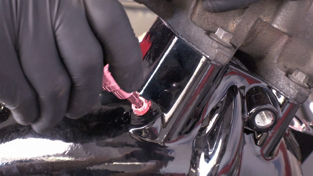
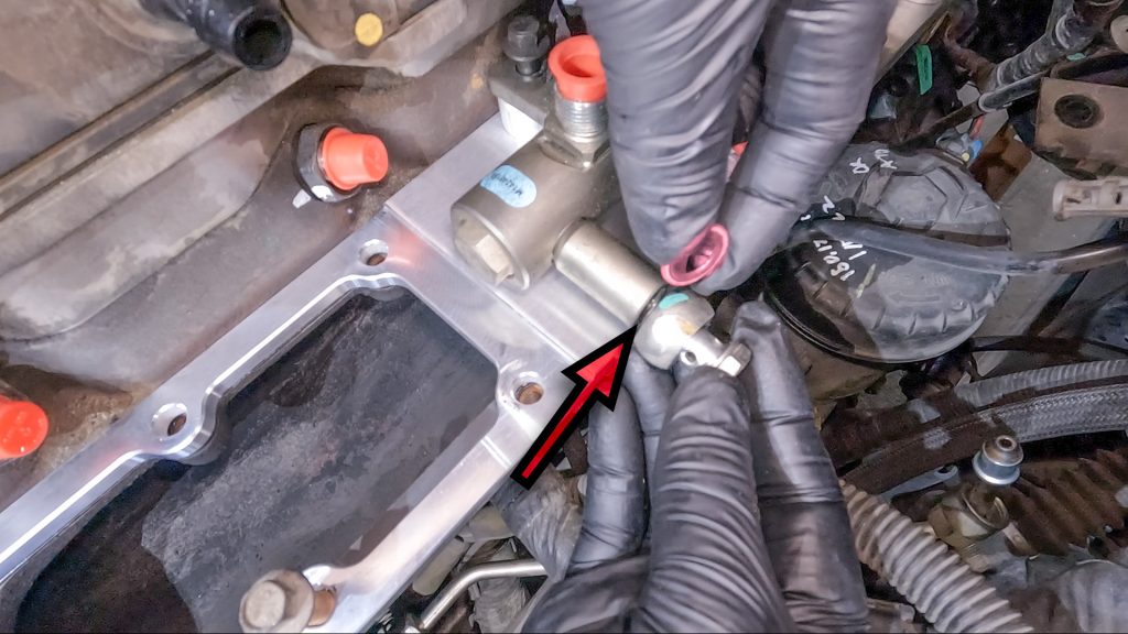
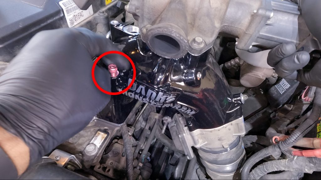
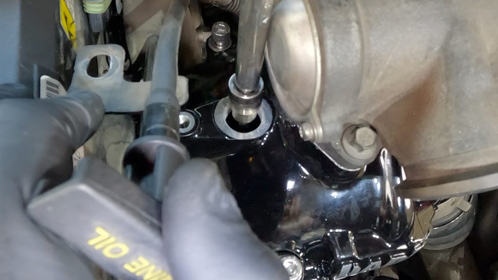
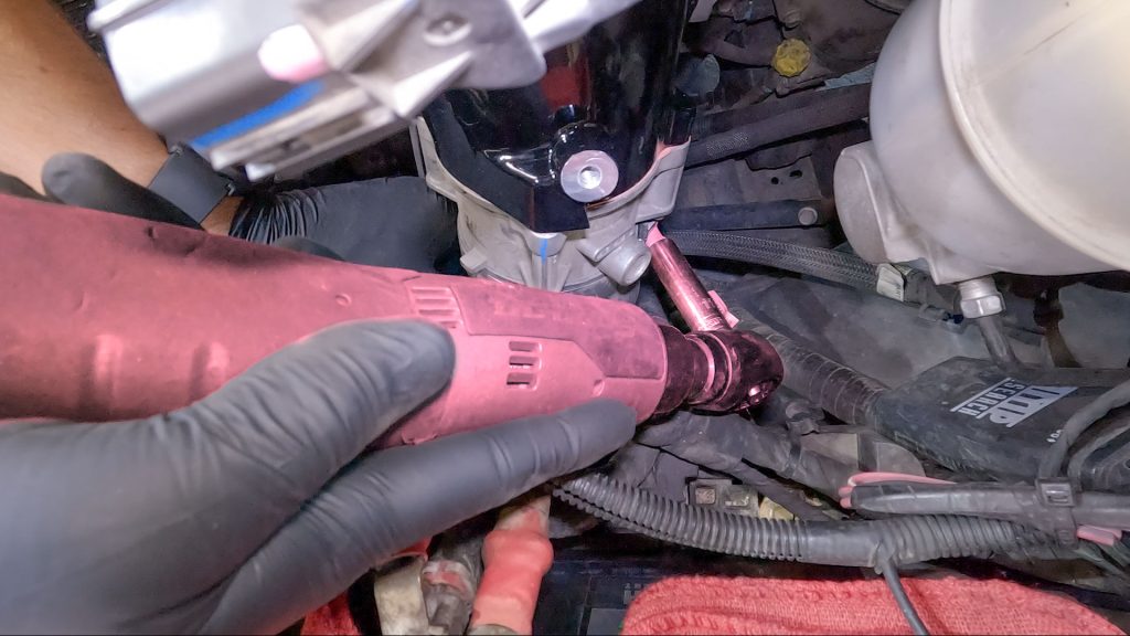
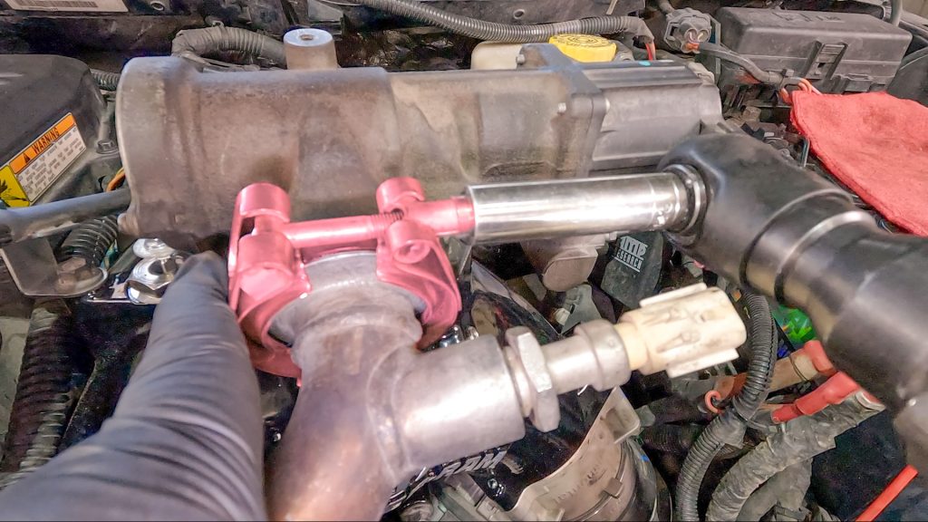
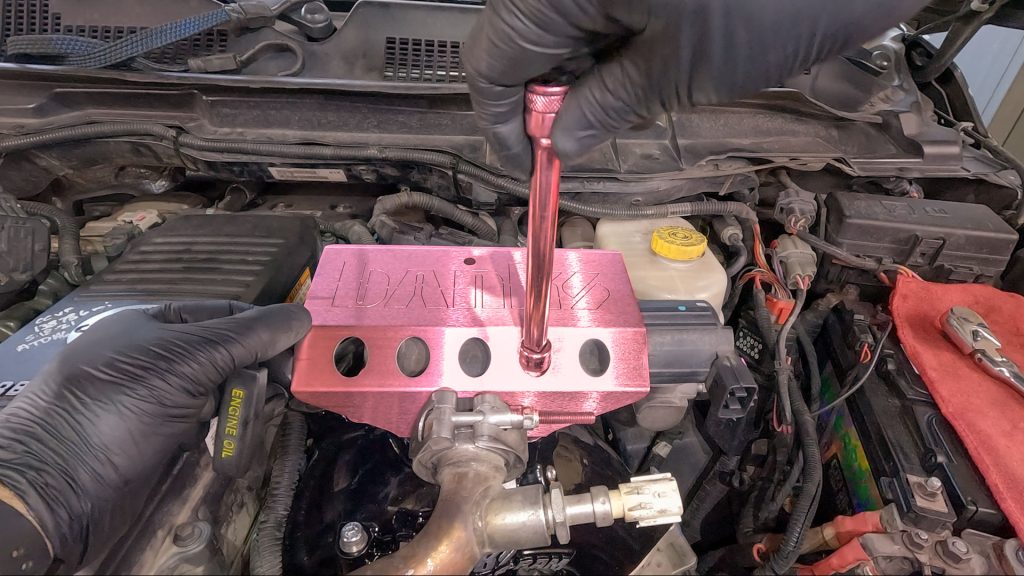
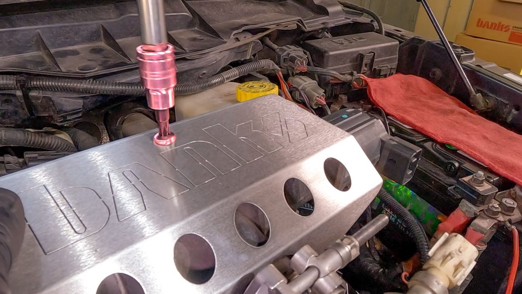
105. Slide Copper Washer Onto Heater Coil
106. Tighten Coil Heater By Hand
Should be tight, but don’t over do it.
107. Install Dipstick Tube Bracket
108. Now Install Forward Flat Blue Injector Plug
Be sure it clicks.
109. Connect Forward PCV Hose to Valve Cover
This is a tight fit, but doable. Wiggle the rubber hose on the nipple a quarter inch, then use a pry tool as a lever to help slide it on.
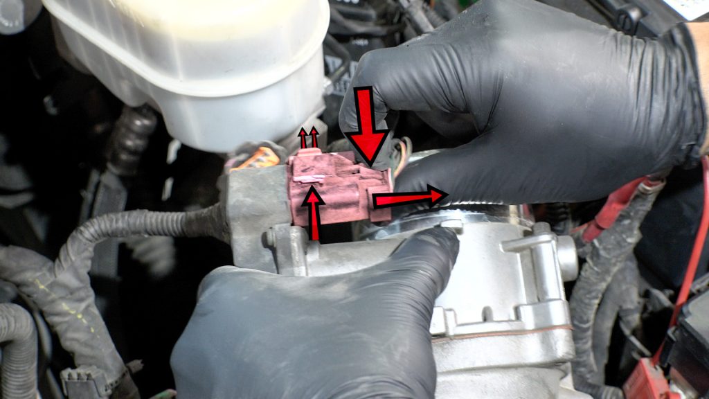
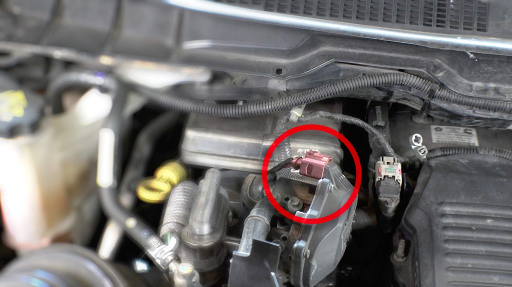
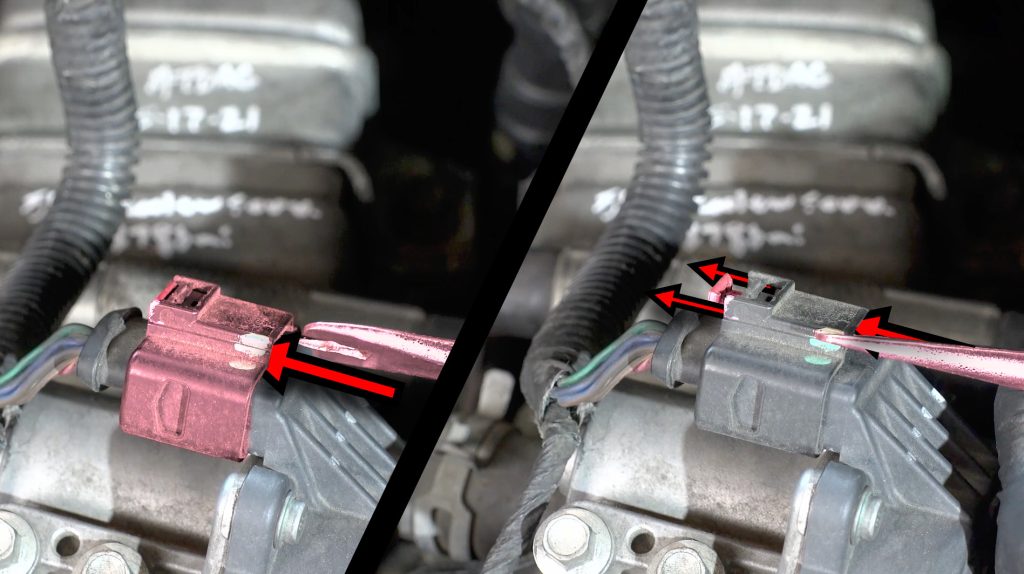
110. Plug In MAP Sensor (Rear of Monster-Ram)
Secure the slide lock back into position.
111. Plug In Throttle Plug
Secure the slide lock back into position.
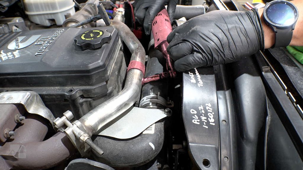
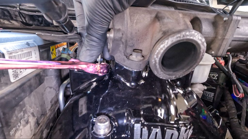
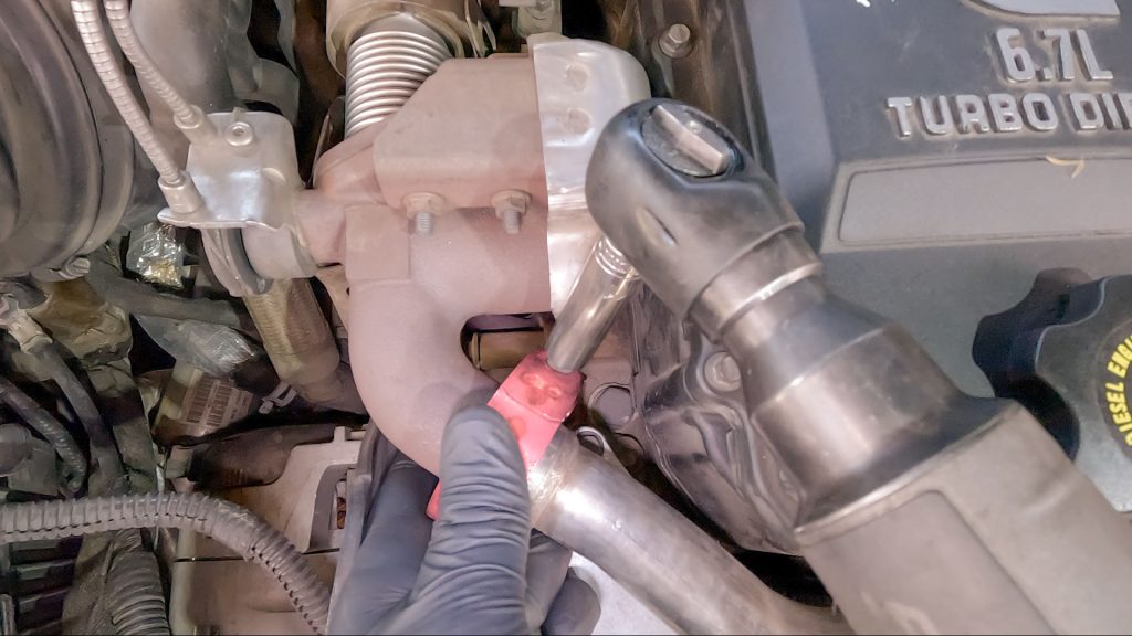
112. Tighten Boost Tube Clamp
113. Remove & Discard 12v Heater Cable P-Clamp
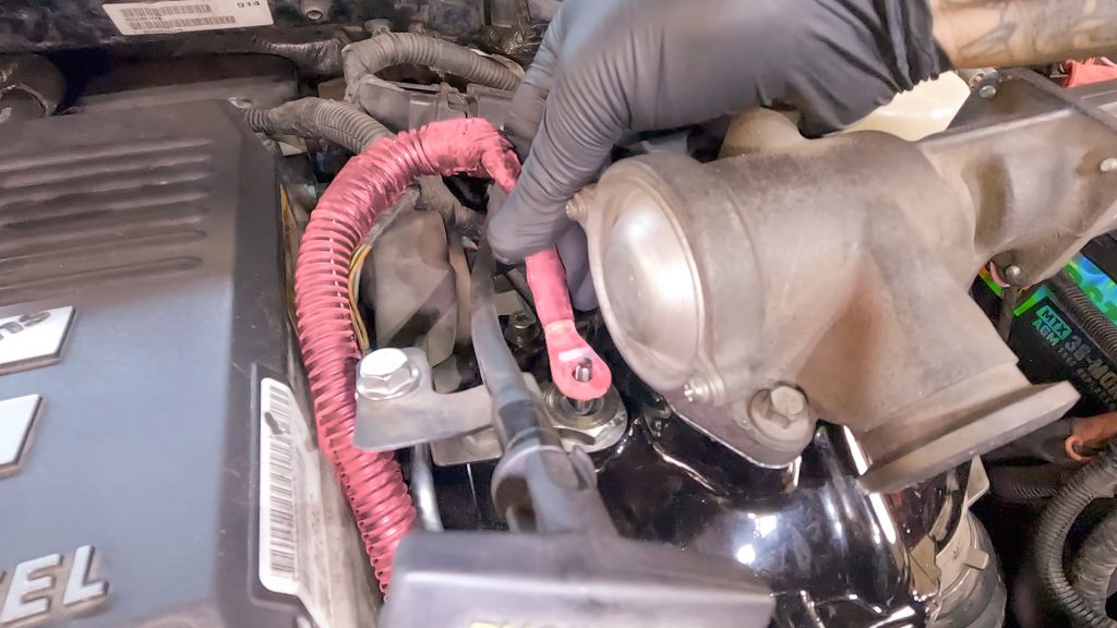
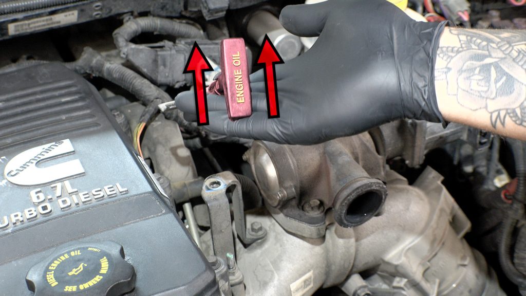
114. Install 12V Heater Wire Locker To Coil Heater
Bend 12V Cable around as shown over the stud.
12V cable should be sandwiched in-between both nuts and the included lock washer
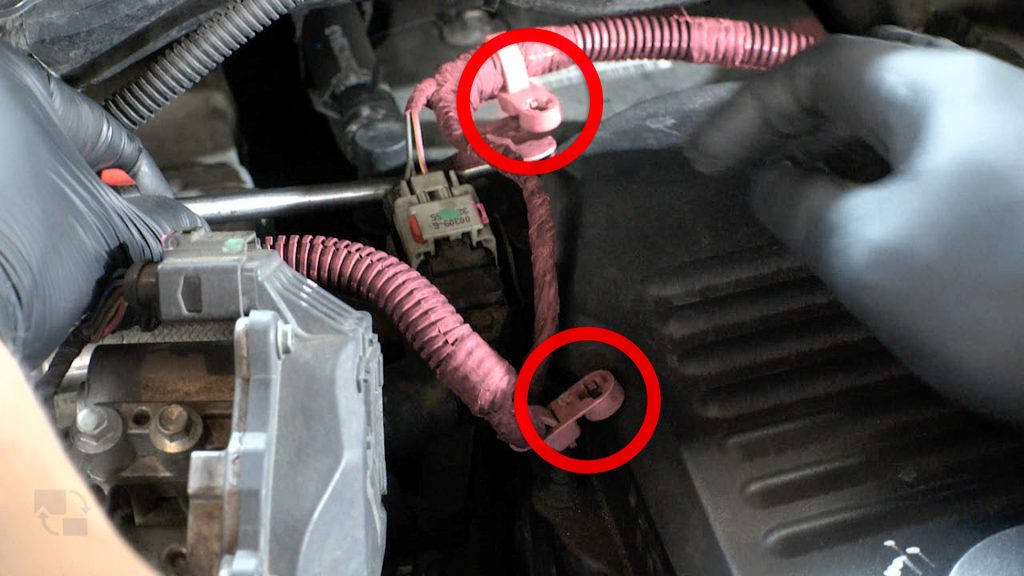
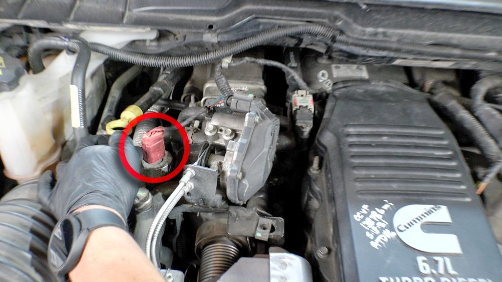
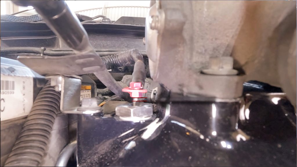
115. Tighten 12V Heater Nut
Be sure to use a wrench to hold the lower nut when tightening the top nut.
Failure to do this can cause the stud to break off, or cause the nuts to walk potentially touching the body of the truck.
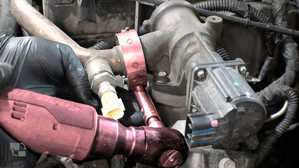
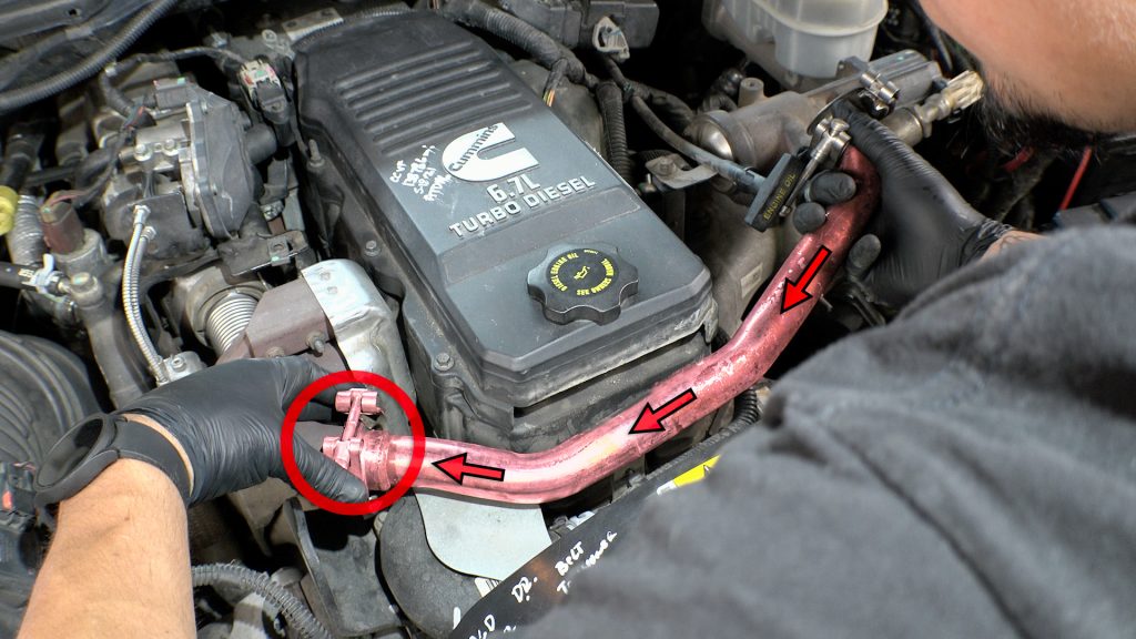
2007.5-2012 EGR Re-installation
116A. Flat Washer Goes On Passenger Side of EGR Tube
117A. Put Clamp Over Union & Hand Tighten
118A. Conical Gasket Goes On Driver Side of EGR Tube
119A. Tighten Driver Side Clamp
120A. Tighten Passenger Side Clamp
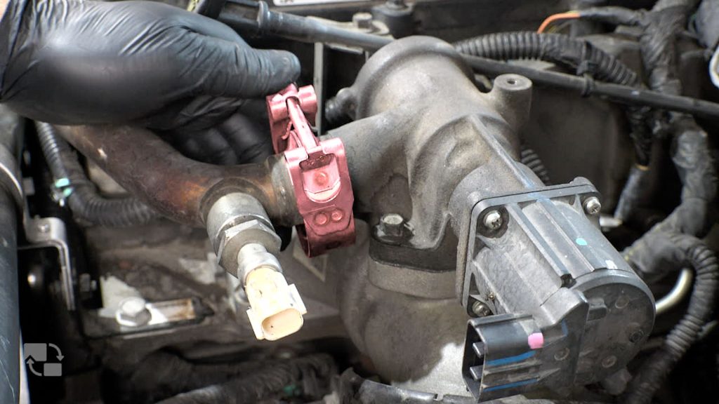
121A. Loosen Front Bolts on EGR Valve
122A. Install EGR Heat Shield and Tighten Bolts
123A. Place Rear Heatshield Spacer & Screw
Use a drop of thread locker on the screw to prevent it from vibrating out.
124A. Tighten Torx Head Screw
2013-2018 EGR Re-installation
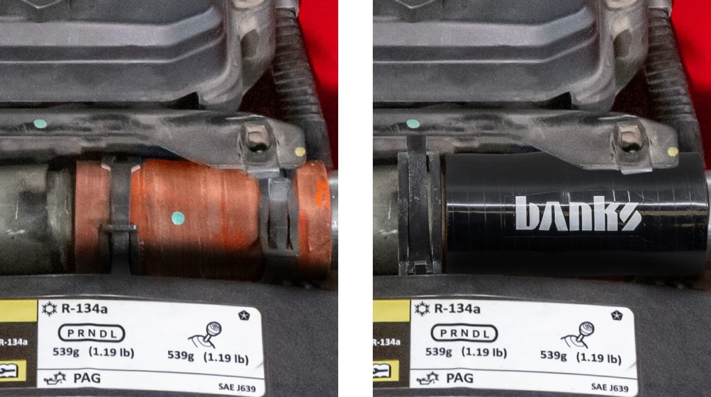
116B. Replace the OE Center EGR Hose with the Banks Silicone Hose.
Be sure to get one constant tension clamp on first before installing the Banks Silicone hose.
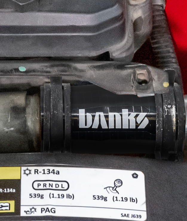
117B. Use the Banks supplied Constant Tension Clamps.
118B. Line up Banks EGR Tube with EGR Valve.
Plug in the EGR Valve to its harness as well.
119B. Bolt on EGR Tube with Banks EGR Cover
Thread back in the EGR temp sensor from the OEM Crossover pipe if you haven’t done so yet.
120B. Place Rear Heatshield Spacer & Screw
Use a drop of thread locker on the screw to prevent it from vibrating out.
121B. Tighten Torx Head Screw
122B. Install Throttle Heat Shield Bolt and Nuts
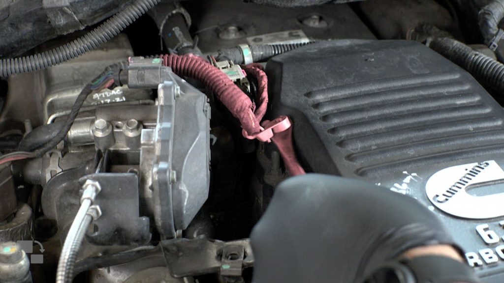
123. Connect EGR Temp Sensor
123A. Connect EGR Extension & Harness
124. Connect EGR Temp Sensor to harness.
Final Checks
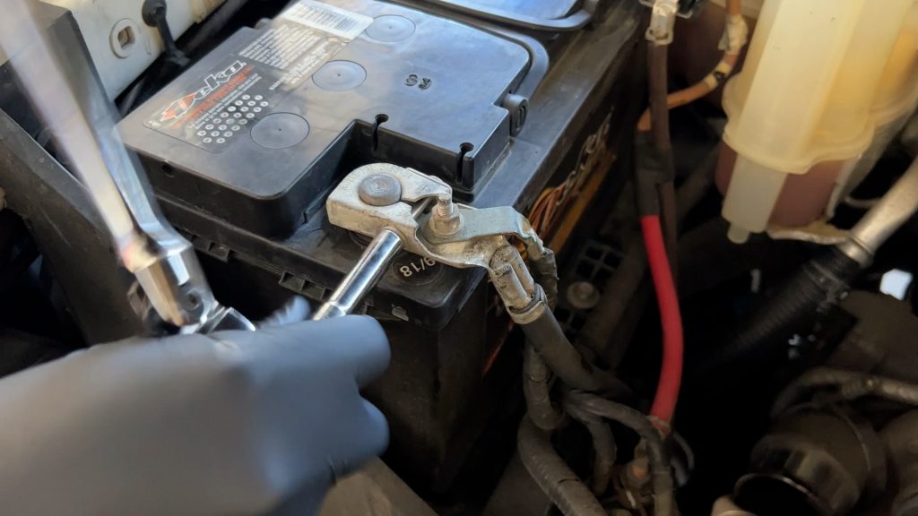
125. Reconnect Batteries
126. First Start May Take 1-2min of engine turnover.
This is normal. The fuel system, rail, and lines need to re-pressurize.
127. Check for leaks.
Check that all harnesses and components are free of moving parts. Check for any leaks while the engine is running. Head out for a short test drive, and double-check for leaks one more time..

CARB EO Label
For smog check purposes, affix the CARB E.O. Label on a visible location under the hood. Banks recommends using the radiator shroud location.