
97700 Banks Ram-Air Intake System for 2018-2025 Jeep JL Wrangler 2.0L
INSTALL INSTRUCTIONS
Part #s
41844, 41844-D & 41866, 41866-D
Banks Ram-Air® Intake System
2018-2023 Jeep JL Wrangler 2.0L
2024+ Jeep JL Wrangler 2.0L/Hybrid
Please read through the following instructions thoroughly before starting your installation. If you have any questions please visit our Support Page.

- 8mm or 5/16” nut driver or flat end screwdriver
- Phillips screwdriver
- 10mm socket and ratchet or wrench
- Clip pry/remove tool
- Longnose pliers
General Assembly

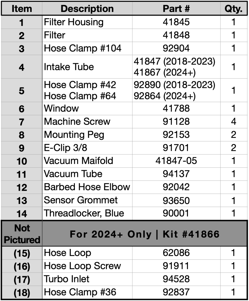
Bill of Materials
Note: 2024+ kits use an updated intake tube, vacuum tube mounts, and turbo inlet. Install steps have been updated to reflect these minor changes.
Section 2: Removal of the factory intake system

1. Remove the IAT sensor. Pull the locking clip towards you and twist counter-clockwise about 45 degrees until it stops rotating.
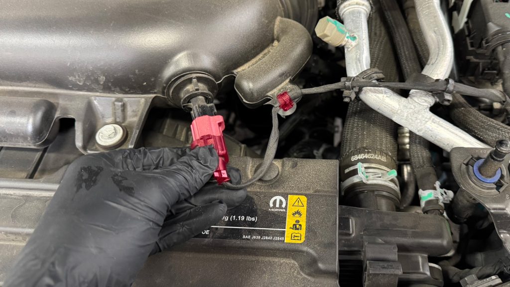
Be sure to free the harness from the factory intake.

2. Unhook the two clips securing the IAT harness to the factory intake tube. Pull the sensor and harness out of the way. Wrap in a shop towel to avoid any damage to the sensor.

3. Remove the two bolts holding the vapor pressure sensor bracket, using a 10mm socket.
For 2024+ Jeeps, skip this step as there is no sensor on the intake here.

4. Cut off the plastic tie that holds the wiring harness to the OEM intake tube.

5. Using a 10mm socket, remove the three bolts holding the OEM intake system.

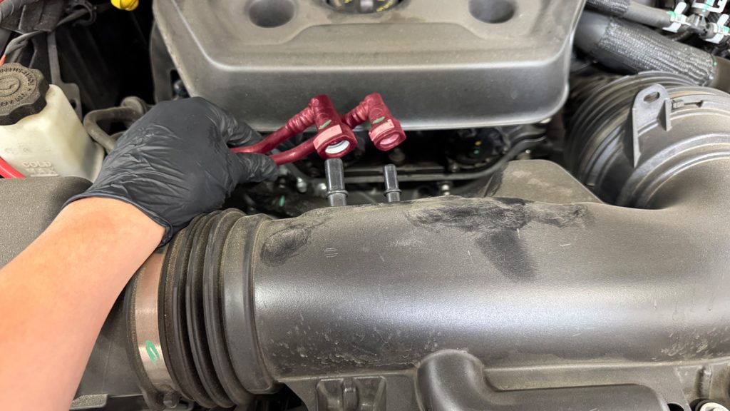
6. Remove the two plastic lines from the air filter housing by pressing the grey tabs and pulling away from the housing.
On 2024+ Jeeps, the lines are located on the intake tube.

7. Remove the clamp that retains the factory air intake tube to the turbo inlet duct.
On 2024+ Jeeps, remove the smaller clamp

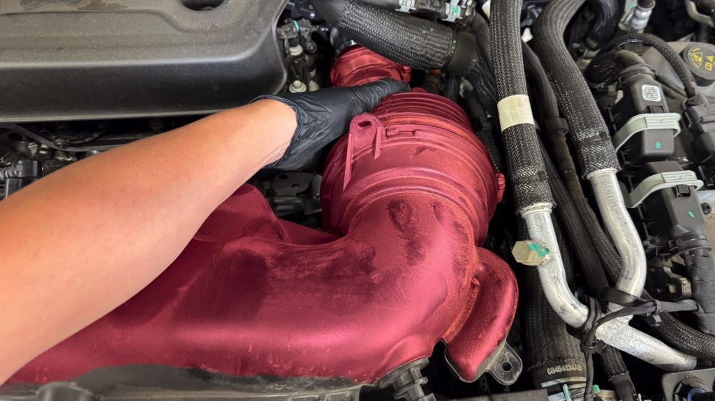
NOTE: Before removing the entire assembly, take note of the sensor connection highlighted in the photo.
IMPORTANT: Be careful not to break the clip that holds the connector in place.

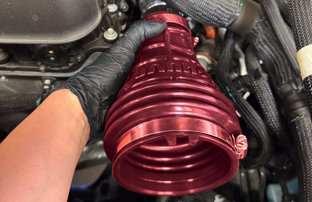
8. Begin removing the assembly by sliding the tube out of the turbo inlet.
On 2024+ Jeeps, you will remove the entire intake, including the stock turbo inlet.

9. Grab the airbox assembly with both hands and pull up until you feel a pop. Pull the assembly out of the engine bay.

10. Before installing your new Banks Ram-Air kit, remove the rubber grommets from the factory airbox and replace them into the engine bay.

NOTE: It’s very important that you install the grommets into the engine bay and NOT onto the Banks airbox.
Section 3: Installing the Banks Ram-Air

11. Slide one aluminum peg through one hole and secure it with the retaining clip using needle nose plyers. Repeat for the other peg.

12. Install the Banks air filter into the Banks airbox and make sure the arrow on the filter is on top.

13. Install the Banks Ram-Air box into the engine bay by pressing down until it pops into the rubber grommets.

14. Secure the Banks Ram-Air box to the sidewall by using the factory bolt and a 10mm socket.

15. Slide the supplied hose onto the vacuum manifold.

16. Take the supplied plastic barbed hose elbow and thread it into the Banks intake tube. The barbed end should be at the 6 o’clock position.
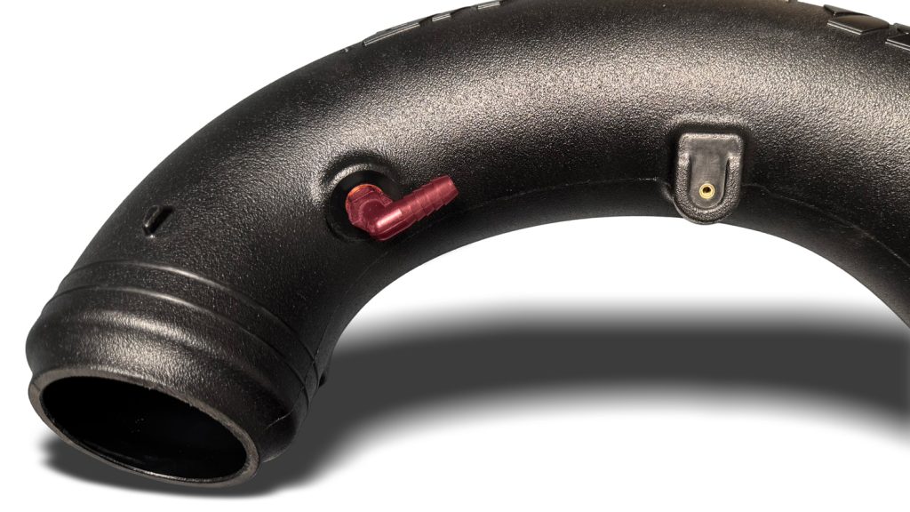
On 2024+ Jeeps, the barb is installed near the turbo inlet, with the barbed end pointing towards the filter.

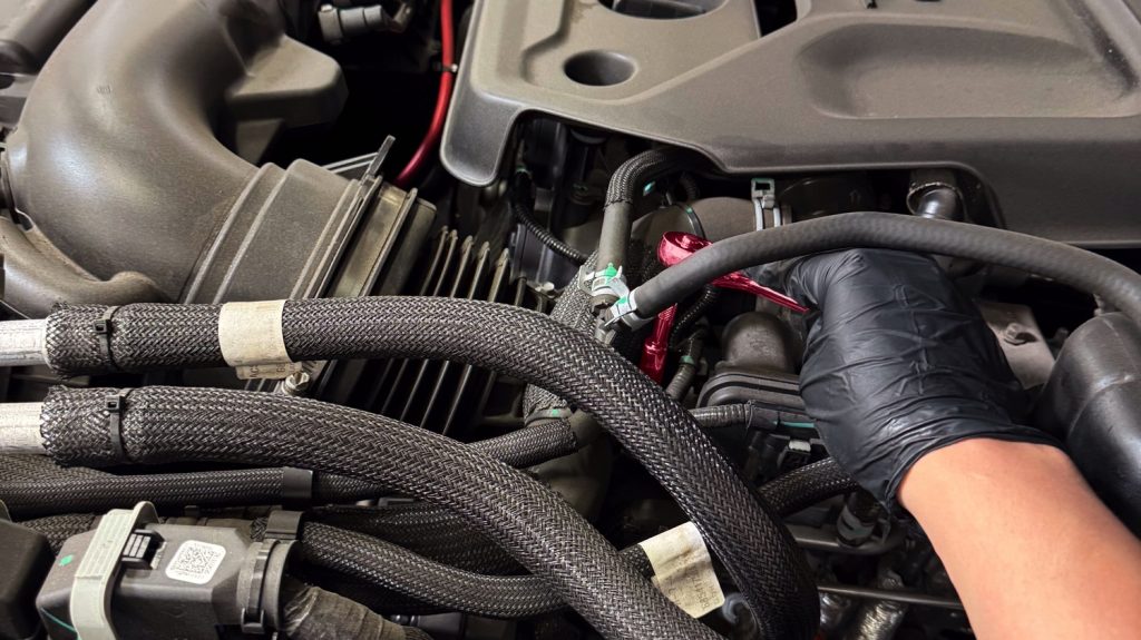
17. Once the fitting is installed, connect the open end of the hose to the fitting. Make sure you can make a loop with the hose, as shown.
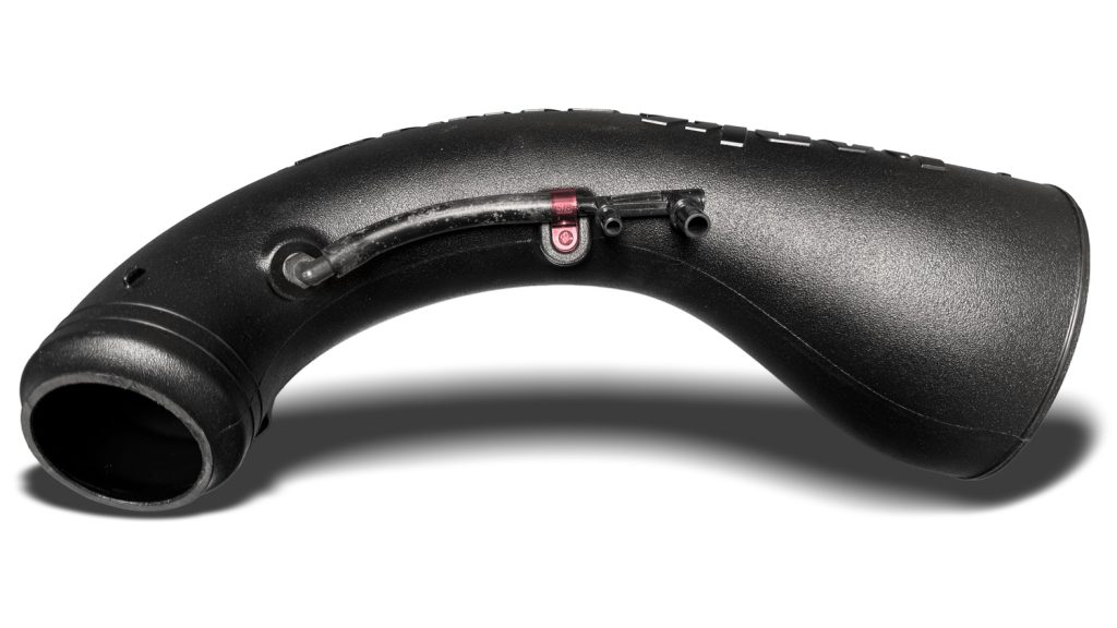
On 2024+ Jeeps, use the supplied hose loop & screw to mount the vacuum hose and manifold to the intake tube.

18. Install the rubber grommet for the IAT sensor onto the intake tube.

19. Place the larger supplied hose clamp onto the filter.

20. Place the smaller hose clamp over the factory turbo inlet duct.
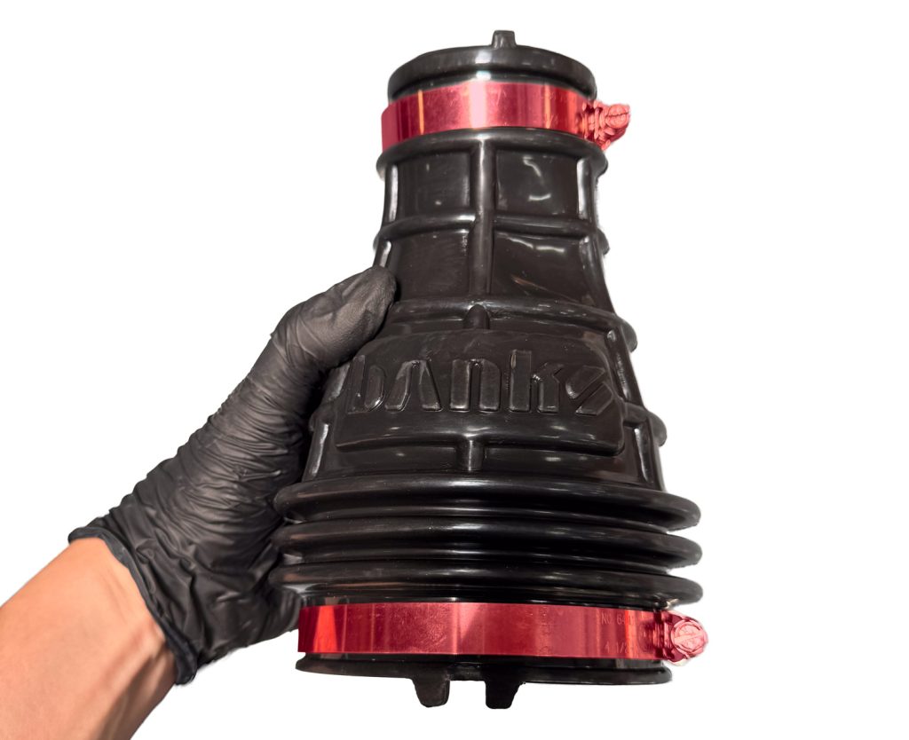
For 2024+ Jeeps, you will put both the #64 and #36 clamp on the new Banks Turbo Inlet.
Then slide the entire turbo inlet and clamps on. Be sure to line up the alignment tab, and tighten the smaller #36 clamp.

21. Install the Banks intake tube by first inserting the large end into the filter and then the smaller end into the OEM turbo inlet duct. Align the duct to the indent on the tube. Align the arrows on the tube and filter. Tighten both clamps.

22. Reinstall the vapor pressure sensor bracket with the factory bolts using a 10mm socket.
For 2024+ Jeeps, skip this step as there is no sensor bracket.

23. Insert the IAT sensor into the rubber grommet.

24. Reinstall the two plastic tubes into the vacuum manifold by pushing until you hear a click.
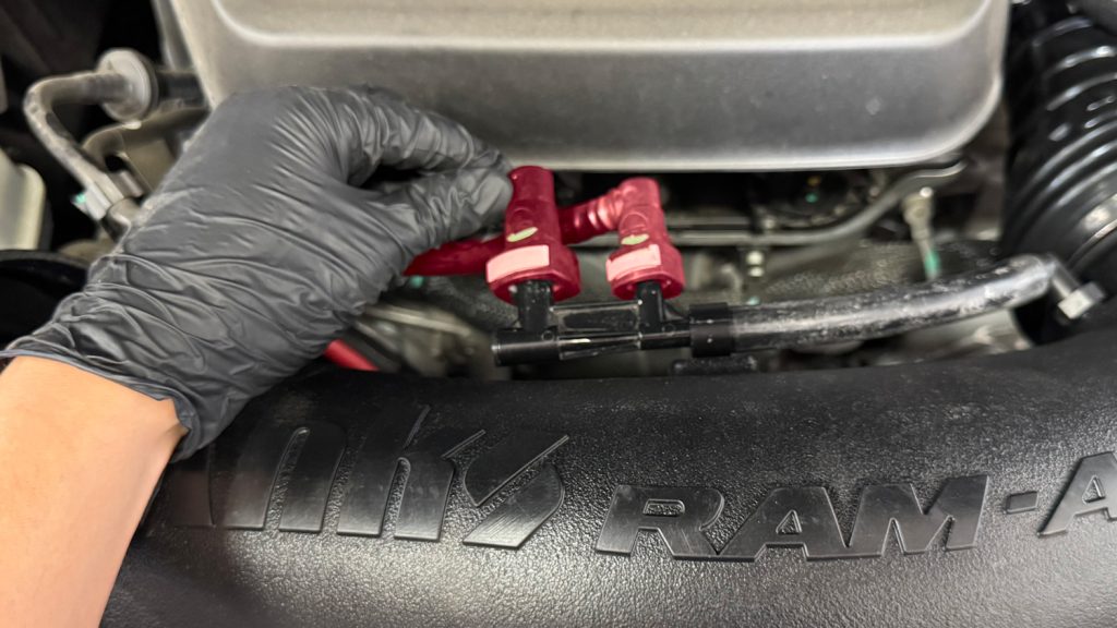
2024+ Jeep vacuum tube location.

25. Install the clear Banks Ram-Air window using the supplied screws and thread locker.
CARB EO Label Placement

CARB EO Label
For smog check purposes, affix the CARB E.O. Label on a visible location under the hood.

Label Placement
Banks recommends using the radiator shroud location.
Congratulations!
You have successfully installed your new Banks Ram-Air Intake. Please see air filter maintenance instructions below.