


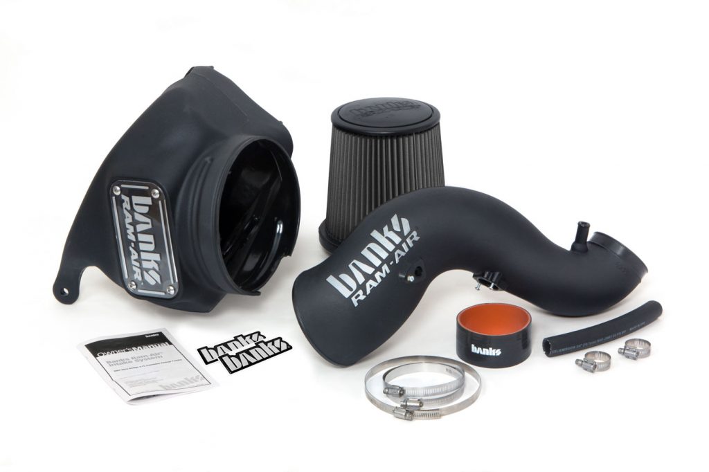
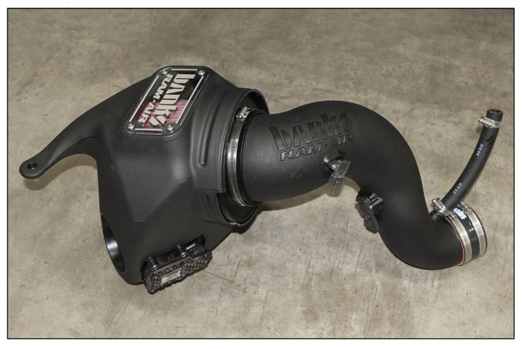
97655 Ram-Air Intake System for 2013-2018 Ram 6.7L Cummins Pickup Trucks
Tools Required:
1. 3/8″ drive ratchets with metric sockets
2. Standard and Phillips head screwdriver
3. Standard and needle-nose pliers
4. Clean shop towels or rags
5. 5/16″ nut driver
6. T-30 driver
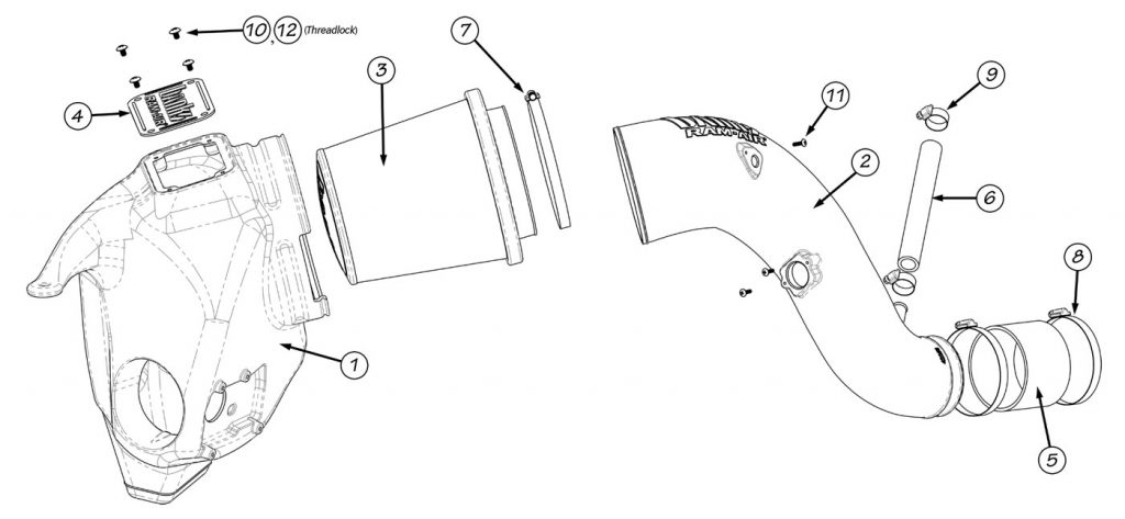
General Assembly
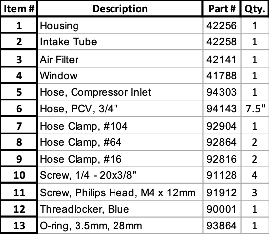
Bill of Materials
Ram-Air Installation
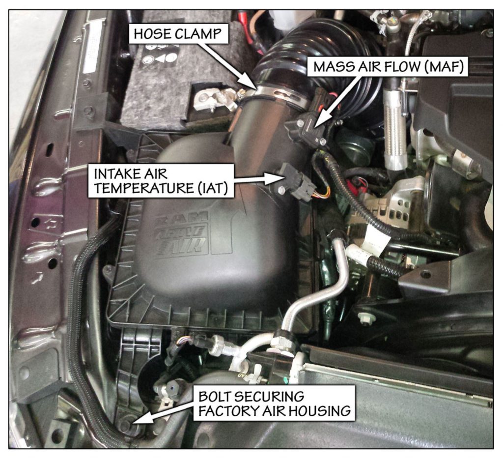
1. Remove the bolt, using a 13mm socket, from the radiator core support that secures the factory air housing and save for reuse.
2. Loosen the hose clamp to the stock intake tube attached to the air housing.
3. Slide the red locking mechanism up on the Mass Air Flow (MAF) sensor connector.
Press the tab on the connector and remove the connector. Press the tab on the Intake Air Temperature (IAT) sensor connector and remove the connector. Pull the plastic anchor holding the wiring harness to the air housing lid and move the harness out of the way.
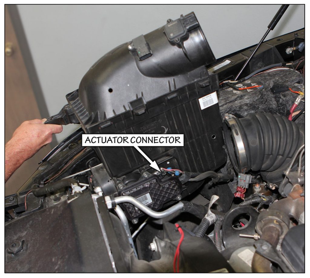
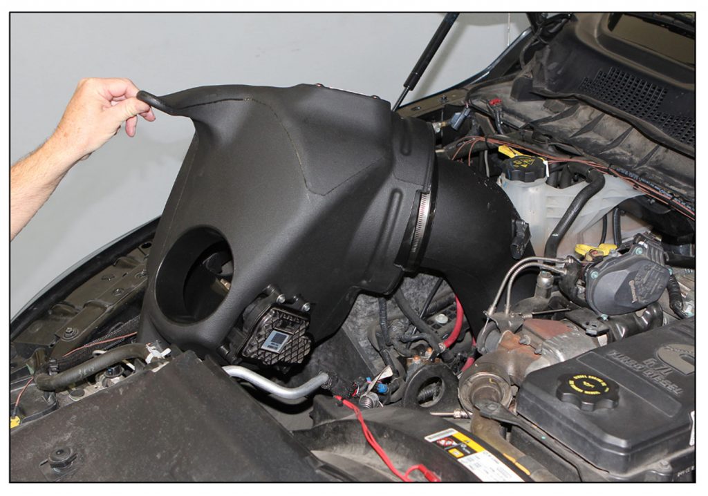
4. Lift the air housing up and partially out of the engine compartment to gain access to the Ram-Active Air® actuator connector on the actuator motor on the side near the bottom of the housing.
Be careful not to pull the housing up too far to damage the wiring harness. Once the housing is pulled out enough to gain access to this connector depress the tab on the end of the connector and disconnect the connector from the motor. The housing can now be removed completely from the vehicle and set aside for disassembly later.
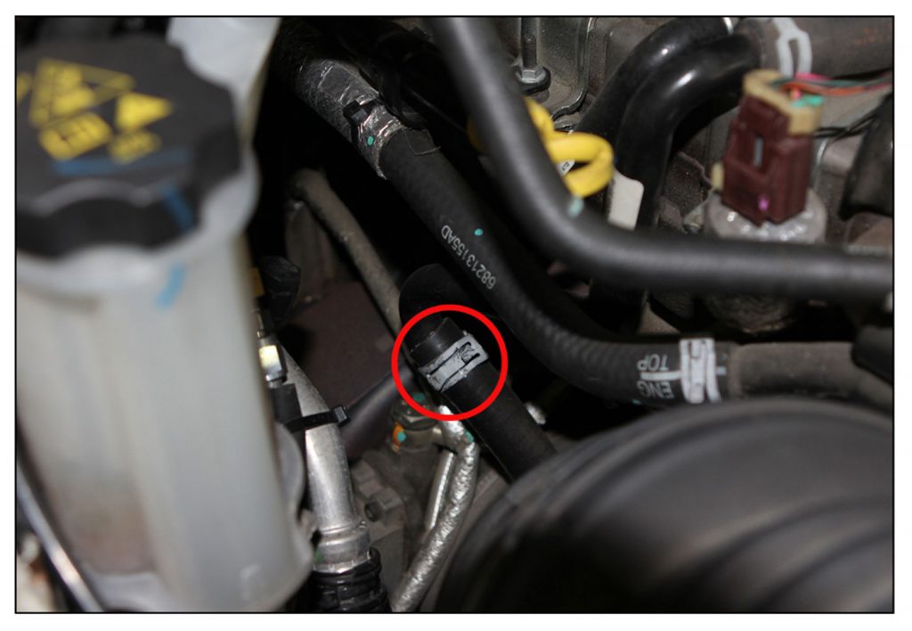
5. Locate the spring clamp retaining the PCV hose.
Using appropriate pliers loosen the clamp and slide it up over the metal tube and out of the way. With the clamp out of the way pull the hose to disconnect from the metal tube. Remove the spring clamp and set it aside.
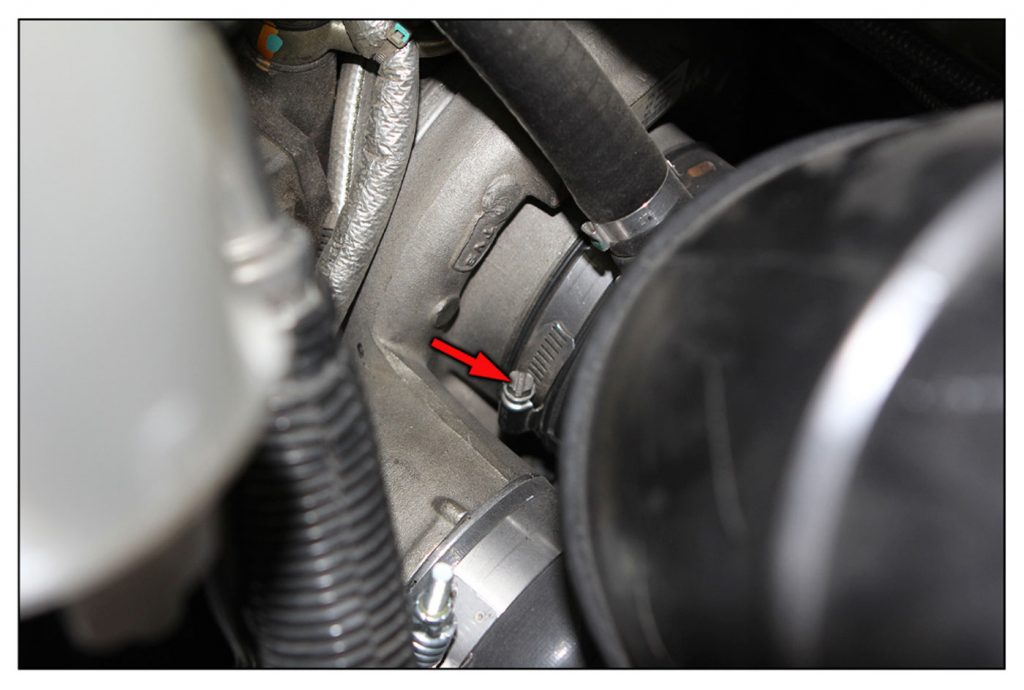
6. Loosen the hose clamp holding the intake tube to the compressor inlet and remove the intake tube from the vehicle.
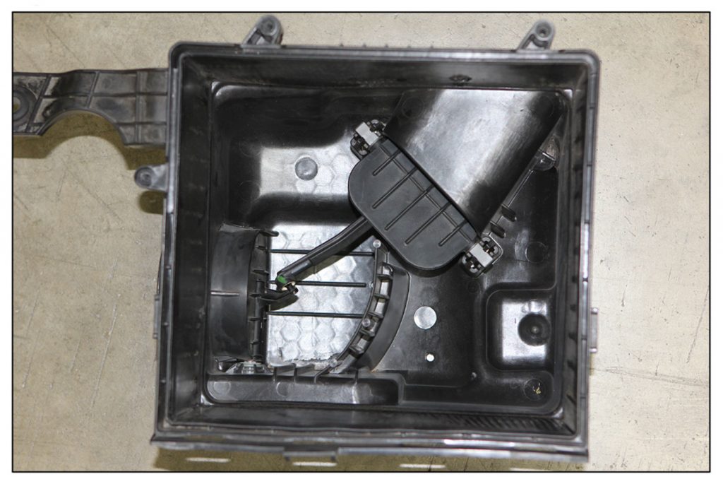
7. Remove the screws retaining the air housing lid and remove the lid and filter. Looking inside the housing you can see the stock Ram-Active Air® doors and linkage.
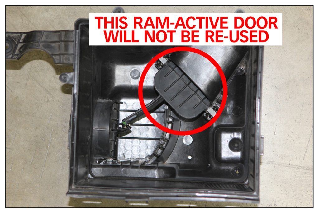
8. The factory Ram-Active Air actuator motor and forward door must be removed from the stock air housing. NOTE: The door that opens toward the passenger fender, as noted in the photo, will not be re-used when installing the Banks Ram-Air housing.
NOTE:
It is important that the electrical connector be disconnected from the actuator motor before beginning to remove the actuator. Do not plug the connector back into the actuator until instructed to do so below after the actuator is completely reinstalled. Failure to do so can cause the actuator motor to rotate to a position that makes it impossible to install.
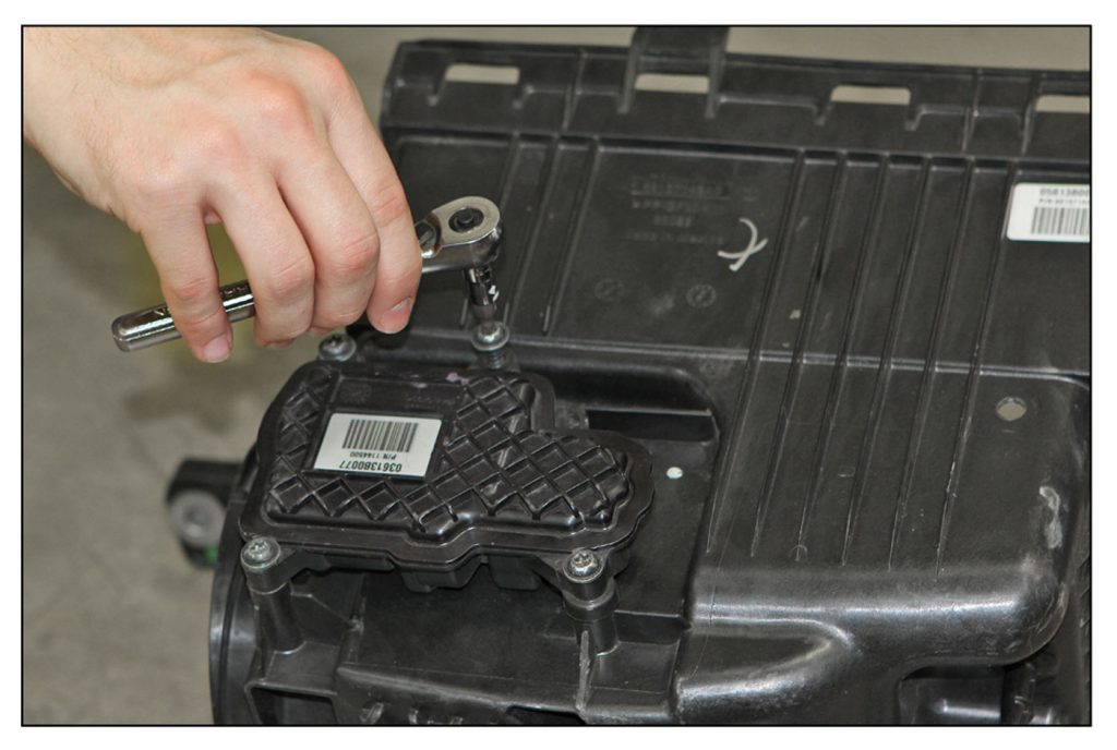
9. Remove the four screws retaining the actuator motor on the side of the housing using a T-30 Torx driver.
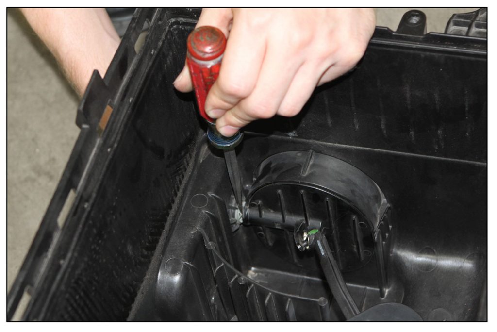
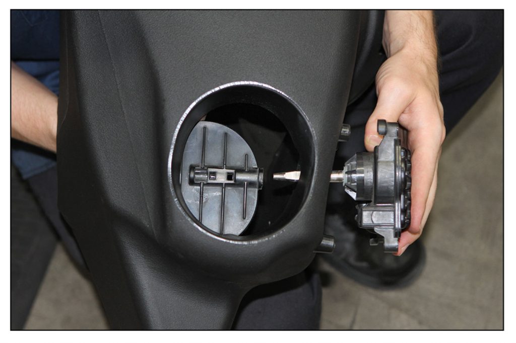
10. Using a flat blade screwdriver inserted between the Ram-Active Air® forward door and the side of the housing gently pry the forward door from the actuator motor shaft and pull the actuator motor from the housing.
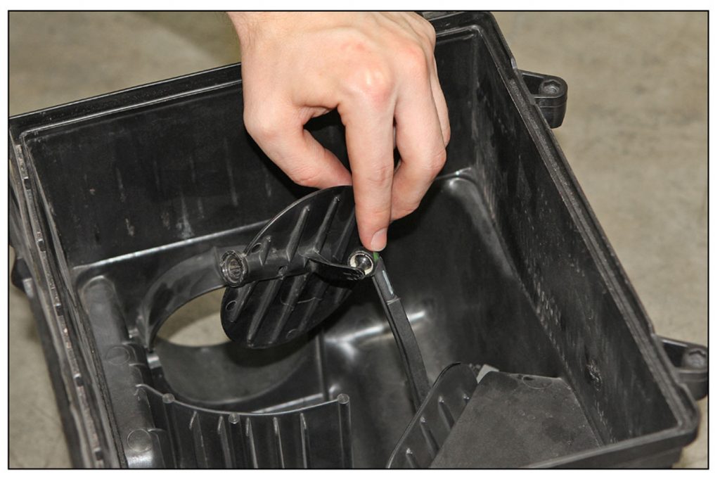
11. With the actuator motor removed, the actuator forward door can now be disconnected from the linkage.
NOTE: The linkage that pairs the front ram-air door and fender door will not be re-used. The door facing the passenger side fender remains in the factory airbox should you ever need to reinstall the factory airbox.
The lever arm on the door is fragile so care must be taken to disconnect the door from the linkage without breaking the arm on the door. To accomplish this, the arm on the door must be supported as close to the joint as possible and disconnect the joint by twisting and pulling simultaneously. Go slow. If the arm does break this will not affect the performance of this Banks Ram-Air Intake system but will prevent the stock actuation if ever returned to stock.
12. Install the Ram Active Air® and actuator motor into the Banks housing. Begin to insert the actuator motor from the side and hold the door over the actuator motor shaft.
Make sure the door and actuator motor are oriented correctly. When the door is fully inserted over the shaft you will feel a click and the door will not pull from the shaft easily.
13. Reinstall the four screws to retain the actuator motor.
14. Remove the IAT and MAF sensors from the stock intake using a 7mm socket. Replace MAF sensor O-ring with supplied 3.5mm O-ring. Install these sensors in the Banks Intake Tube using the supplied screws and a Phillips screwdriver.
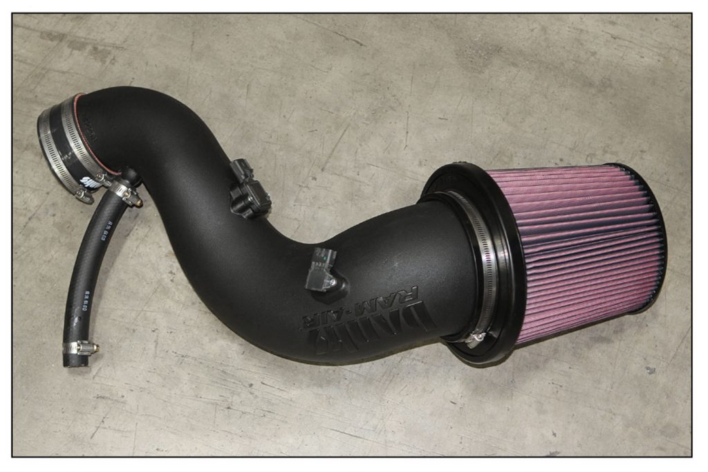
15. Install the PCV hose and two hose clamps along with the compressor inlet hose and its two hose clamps onto the Banks Intake Tube in the orientation shown in the picture. Tighten the clamps retaining the hoses to the tube and leave the other clamps loose.
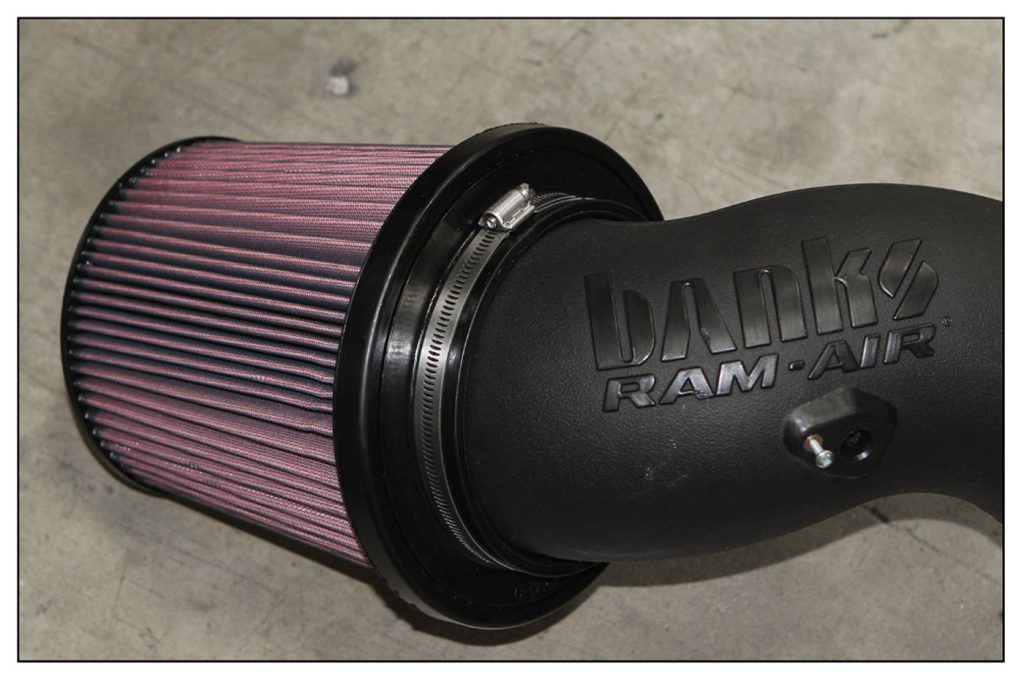
16. Install the Banks Ram-Air Filter onto the Intake Tube and secure it with the hose clamp. The hose clamp must be held up against the base of the filter while tightening the clamp.
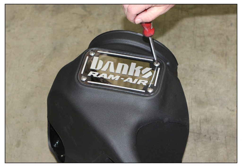
17. Apply blue thread locker to 4 supplied window screw and use to install clear window onto the housing. Do not over-tighten the screw. They just need to be snug.
NOTE:
Window screws may vibrate loose if thread locker is not applied.
18. Install the filter into the housing ensuring that the filter is completely inserted into the housing.
19. Begin to install the Banks Ram-Air assembly into the vehicle.
Before completely install the housing, make sure to reconnect the wiring to the actuator motor. Also, reconnect the wiring to the IAT and MAF sensors and push the red locking mechanism down on the MAF connector.
20. Install the compressor inlet hose over the inlet of the compressor.
21. Insert the Banks housing down into the engine compartment pushing the pins on the bottom of the housing into the rubber grommets on the fender well. Ensure the pins are engaged with the grommets by making sure the housing is firmly held in position.
22. Reinstall the bolt retaining the housing to the radiator core support.
23. Ensure the hose is still completely installed over the compressor inlet and tighten the clamp to secure the hose to the compressor.
24. Install the PCV hose over the metal tube of the PCV system along with the hose clamp. Once the hose is fully installed over the metal tube tighten the clamp to secure the hose.
NOTE:
On some vehicles the metal tube can become loose and move out of position. It may be necessary to move this metal tube in order for the PCV hose to fit correctly. Take care when repositioning this metal tube to not use excessive force and damage the tube. If the PCV hose is too long it may need to be trimmed to prevent the hose from kinking.
Air Filter Cleaning
To clean your air filter, please refer to the instructions found here.

CARB EO LABEL
Please use the following CARB-approved emissions label and EO label location guidelines. We generally use the radiator shroud location.
Congratulations!
You’ve completed the installation of the Banks Ram-Air Intake System. Check all hose clamps for tightness and connectors for a sure fit. Ensure there is proper clearance around the intake tube and that all wiring is secured away from hot or moving parts.