97764 Derringer High Output for 2020-2025 GM L5P with Single Alternator
INSTALL INSTRUCTIONS
Part #s
(67106 | 67126), (67207 | 67127), (67108 | 67128)
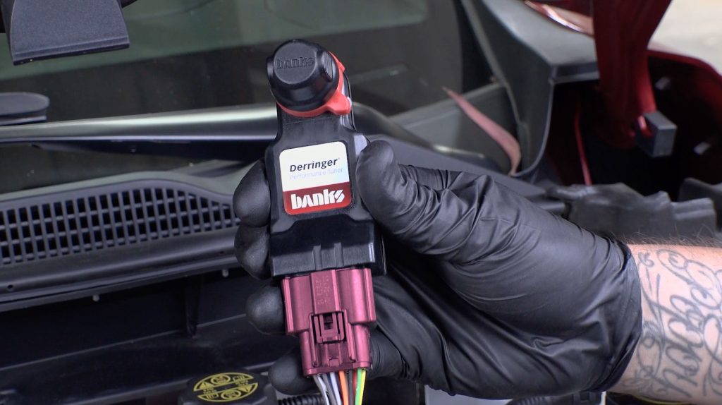
Banks Derringer® Diesel Tuner
Install guide for vehicles with a single alternator.
2020-2022 (67106 | 67126)
2023 (67107 | 67127)
2024-5 (67108 | 67128)
Please read through the following instructions thoroughly before starting your installation. If you have any questions please visit our Support Page.
General Installation Practices
Disclaimers
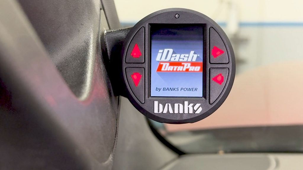
STOP: The new Derringer High Output only works with an iDash Pro running firmware version 1.06 or newer.
The first time you connect the iDash Pro to your Bank’s mobile app, you’ll be prompted to update to the latest firmware, wirelessly, if an update is available.
If you have an existing iDash SuperGauge or iDash DataMonster, you can use it as a secondary expansion gauge.
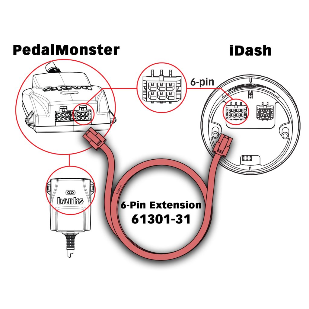
If you already have a PedalMonster and do not currently have an iDash, you will need a Banks 6-pin to 6-pin extension cable to connect your existing PedalMonster to your new iDash.
This is mentioned again in Section 4 Step 9.

Disconnect Battery
Before starting the install, disconnect both negative battery terminals for at least 15 min.
The ECU will hold some residual charge, so disconnecting sensor plugs early may cause a check engine light upon completion of your install.
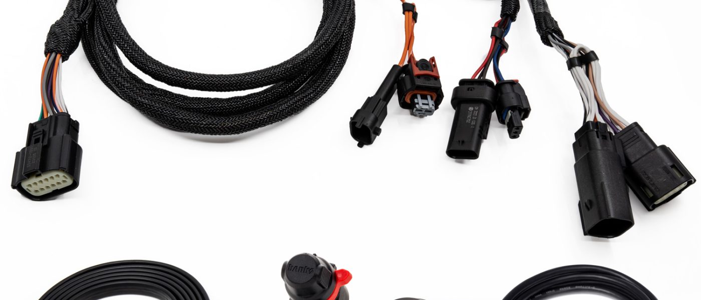
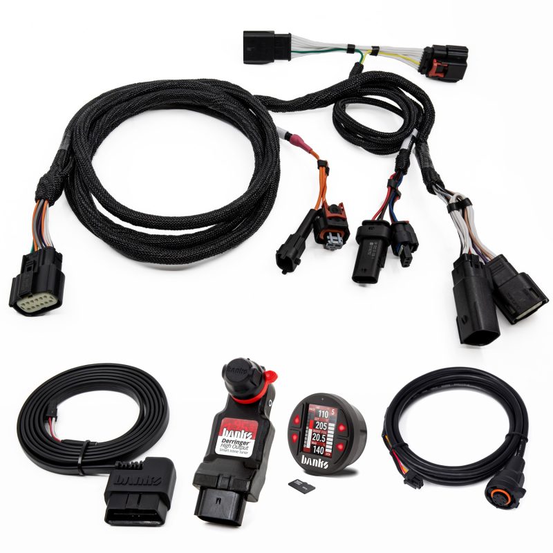
Section 1: Installation of Wire Harness and Derringer Tuner

Derringer High Output Tuner System Configuration
Derringer Tuner System Configuration
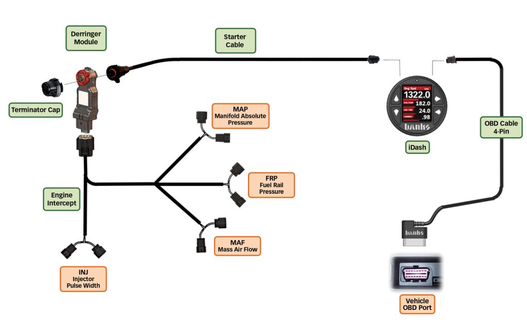
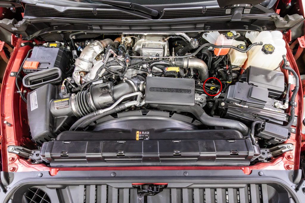
The Derringer High Output tuner uses a new sensor intercept harness when compared to previous Derringer Tuners. The High Output tuner will tap into a total of 4 sensors on the engine. Let’s take some time to familiarize yourself with where these sensors are located, as positions change depending on the production year of your truck.
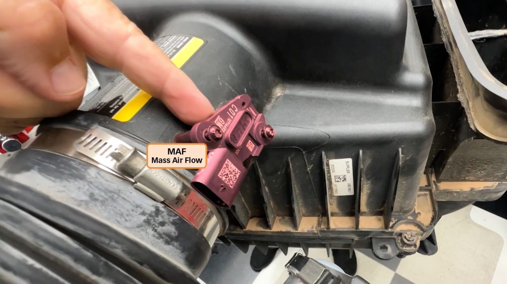
1) M.A.F. (Mass Air Flow)
The Mass Air Flow sensor is located on the plastic intake tube, just after the air filter for the engine.
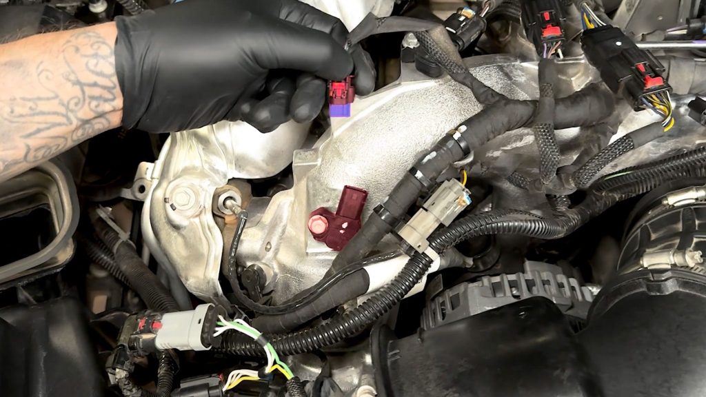
2) M.A.P. (Manifold Absolute Pressure)
The Manifold Absolute Pressure sensor is located behind the EGR valve and is bolted onto the cast aluminum intake manifold. Depending on what year range your truck is, this sensor will be in one of two places.
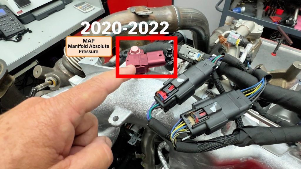
2020-2022 Years
The (Temperature)/Manifold Absolute Pressure sensor is located on top of the cast aluminum intake manifold.
If your truck only has one sensor here, you will plug it into the top one.
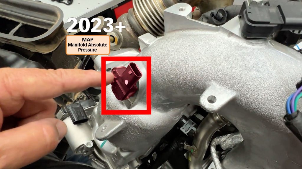
2023+ Years
For late 2023+ model years, the top TMAP sensor is split in two. The pressure sensor is lower on the intake manifold, closer to the EGR valve.
If your truck has two sensors, you will plug into the lower of the two.
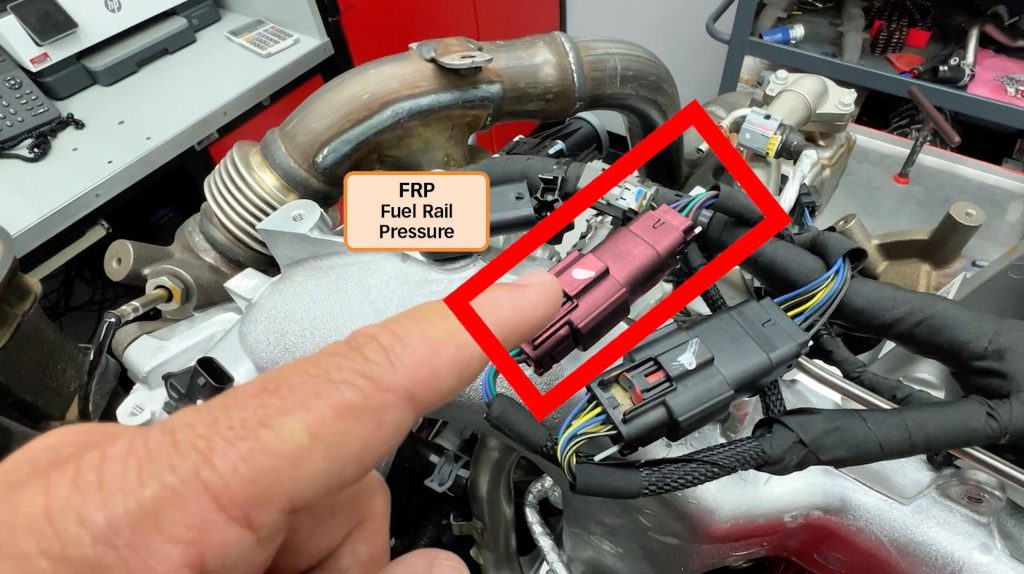
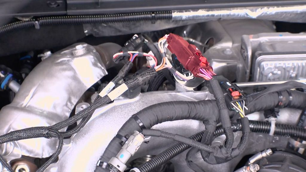
3) F.R.P. (Fuel Rail Pressure)
The Fuel Rail Pressure sensor plug is located on top of the cast aluminum intake manifold right after the MAP sensor(s) are.
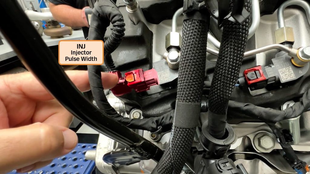
4) I.N.J. (Injector Pulse Width)
The last location that will connect your Derringer Harness to is the fuel injector for cylinder #2. It is located on the driver’s side of the engine towards the nose of the truck and is normally covered with a plastic cover on the engine.
Now that you are familiar with the four sensors and plugs the Derringer will intercept, lets continue with the installation.
Section 2: Derringer Harness Intercepts
2.0 Disconnect Battery
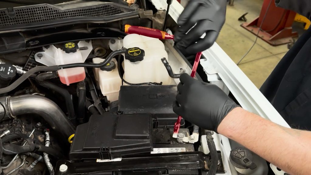
WARNING:
Ensure the engine bay is cool. Remove keys from the ignition. Disconnect both battery GROUND (-) cables. Secure the cables so that they do not come in contact with the battery posts during the installation.
NOTE: If the ECU is powered on when the sensors are disconnected, your vehicle will show diagnostic trouble codes. These codes can be cleared later using the iDash.
Leave them disconnected for 15 minutes prior to separating any connectors.
This allows the truck’s ECM to go to sleep. Do not perform open heart surgery on patience while awake.
2.1 Mass Air Flow Intercept (MAF)
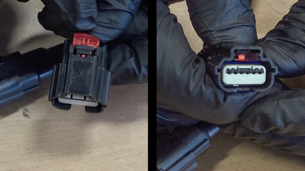
To disconnect the OEM harness, slide back the OEM harness connector’s red locking tab.
Use your thumb to depress the black plastic tab just in front of the red tab. This will release the connector and you can pull it away from the OEM FRP connection.
For vehicles with a stock air intake.
A) Plug in the Derringer harness plug with the MAF label on it, into the Mass Air Flow sensor.
Plug the other end of the Derringer MAF intercept harness, into the factory harness.
Check that both red locking tabs are pressed in.
For vehicles with a Banks Ram-Air Intake.
B) If you have a Banks Ram-Air, be sure to plug-in the Air Mass Control Module into your intake first.
Connect the other end of the Derringer MAF intercept harness to the factory harness.
Check that both red locking tabs are pressed in.
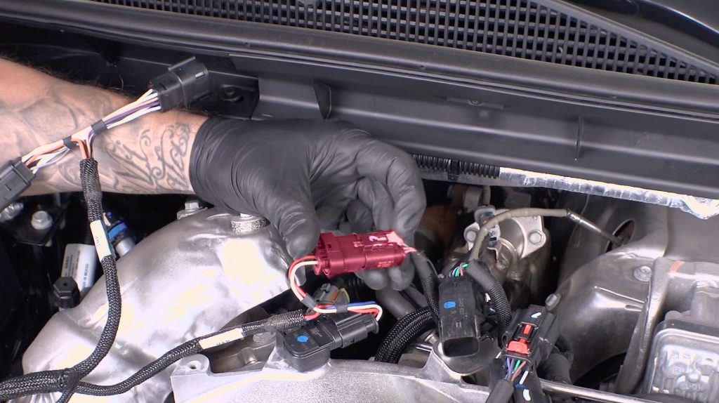
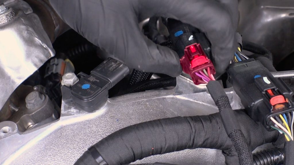
2.2 Manifold Absolute Pressure Intercept (MAP)
Next you will intercept the (T)MAP sensor. Remember, if your truck is a 2020-22 model year, you’ll have one sensor on the top that you will intercept. For late 2023 and newer trucks with dual sensors, you will intercept the lower one.
The installation steps below are for a 2020-2022 truck. Be sure to connect your derringer harness to the correct sensor for your year range, as the plugs will not fit onto the wrong sensor.
2020-2022
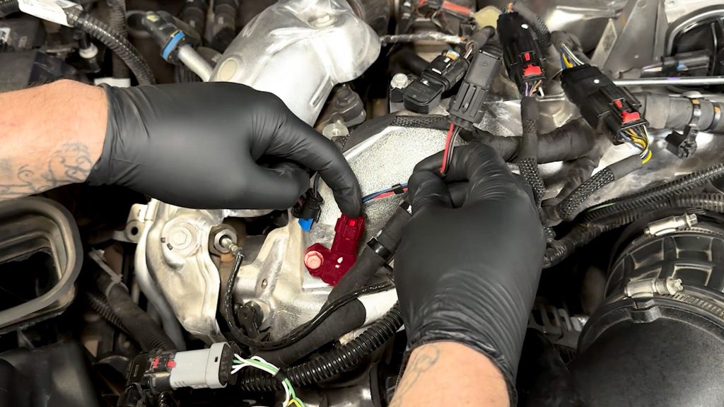
A) Slide the red locking tab back, and depress the black portion in front to release the sensor.
The install steps below are on a 2023+ truck. Be sure to connect your derringer harness to the correct sensor for your year range, as the plugs will not fit onto the wrong sensor.
2023.5+
B) Slide the red locking tab back, and depress the black portion in front to release the sensor.
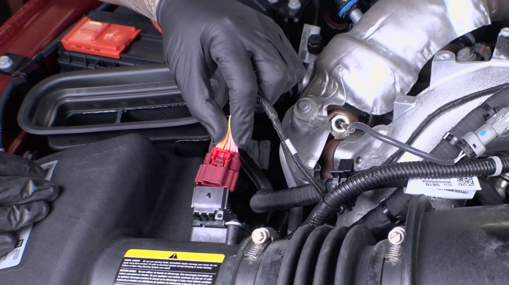
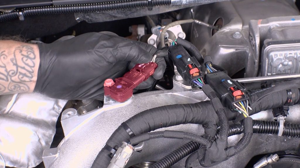
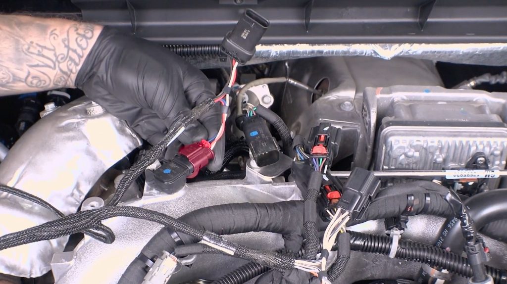
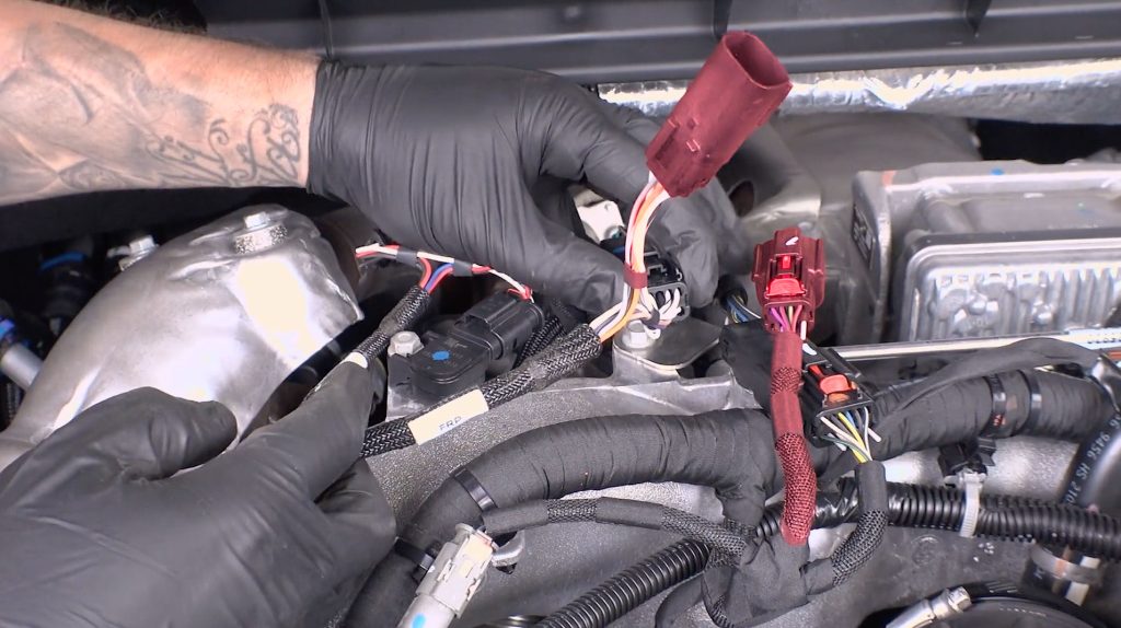
2.3 Fuel Rail Pressure Intercept (FRP)
Disconnect the FRP sensor, located directly behind the top-mounted (T)MAP sensor.
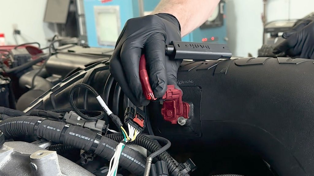
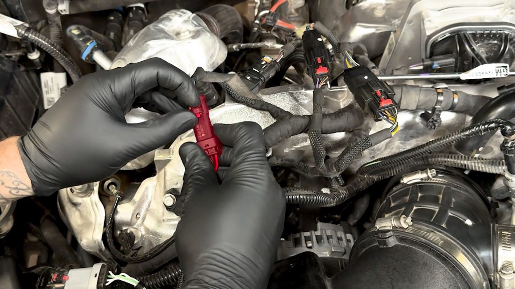
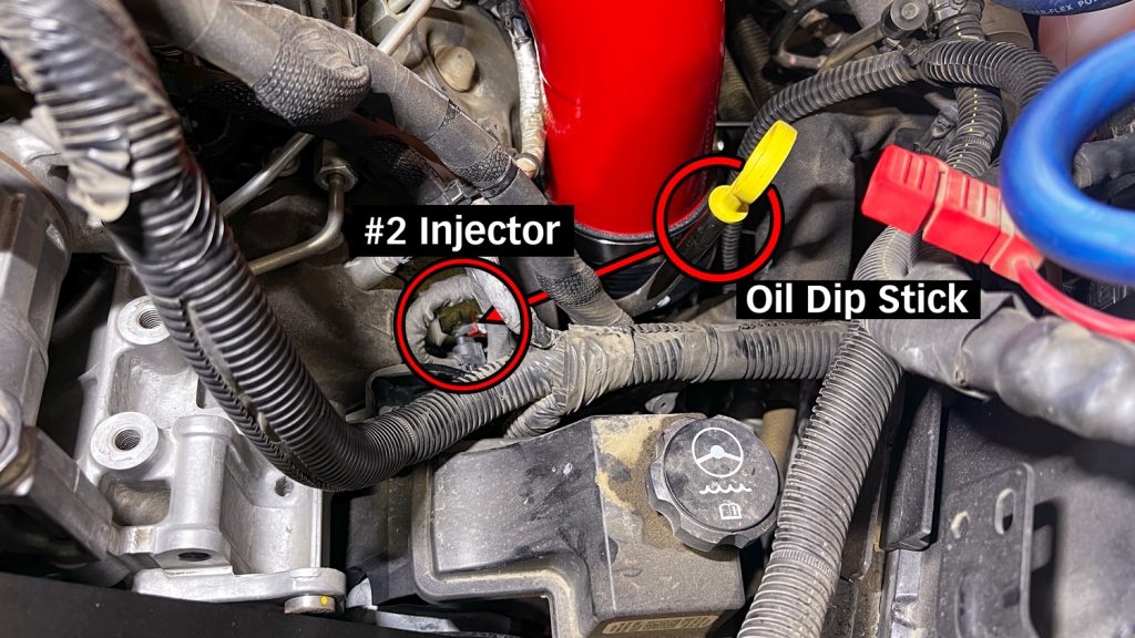
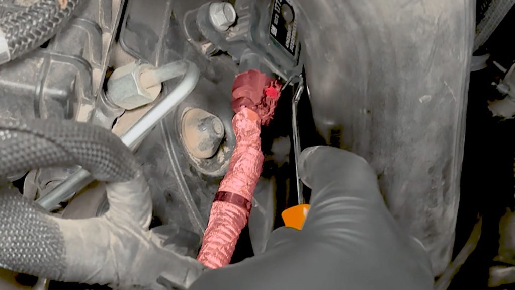
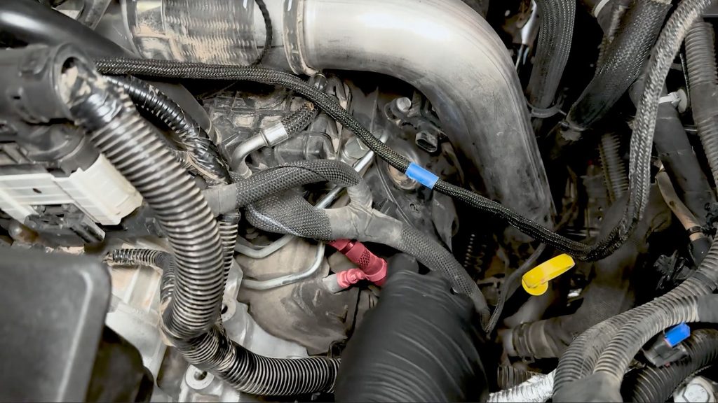
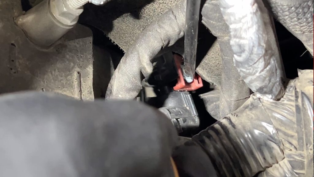
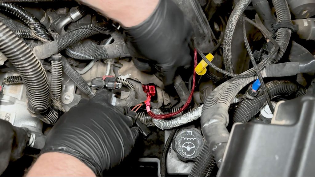
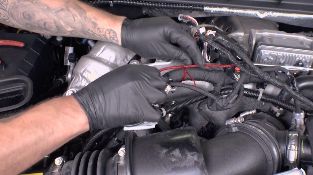
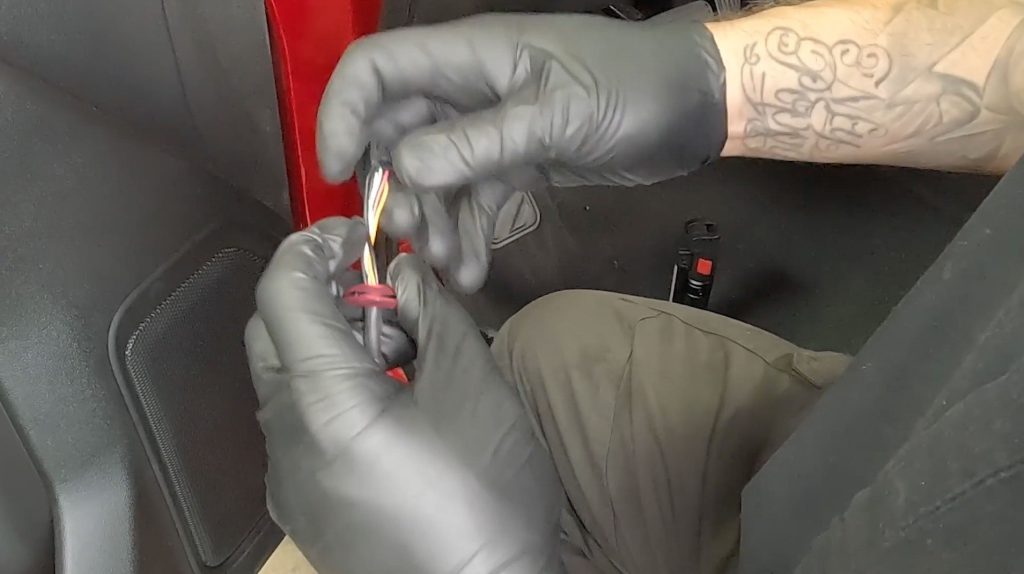
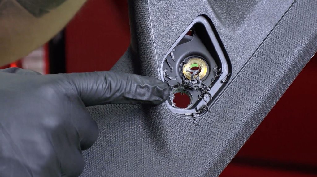
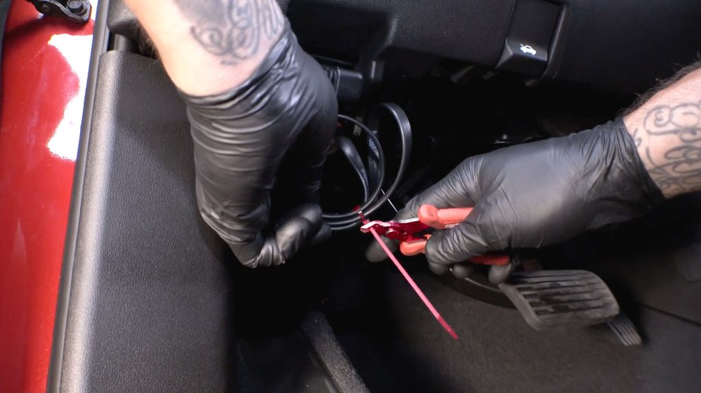
2.4 Injector Intercept (INJ)
Locating the #2 Injector can be a bit tricky. First find the yellow dipstick, then look down to the left.
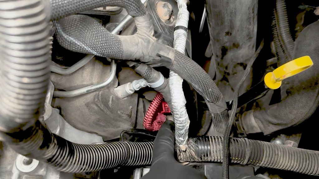
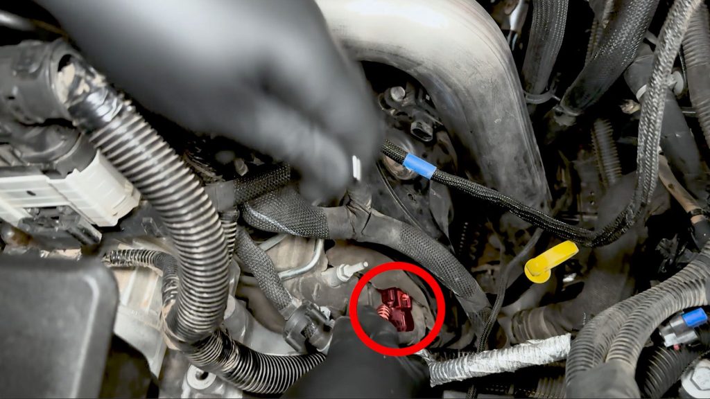
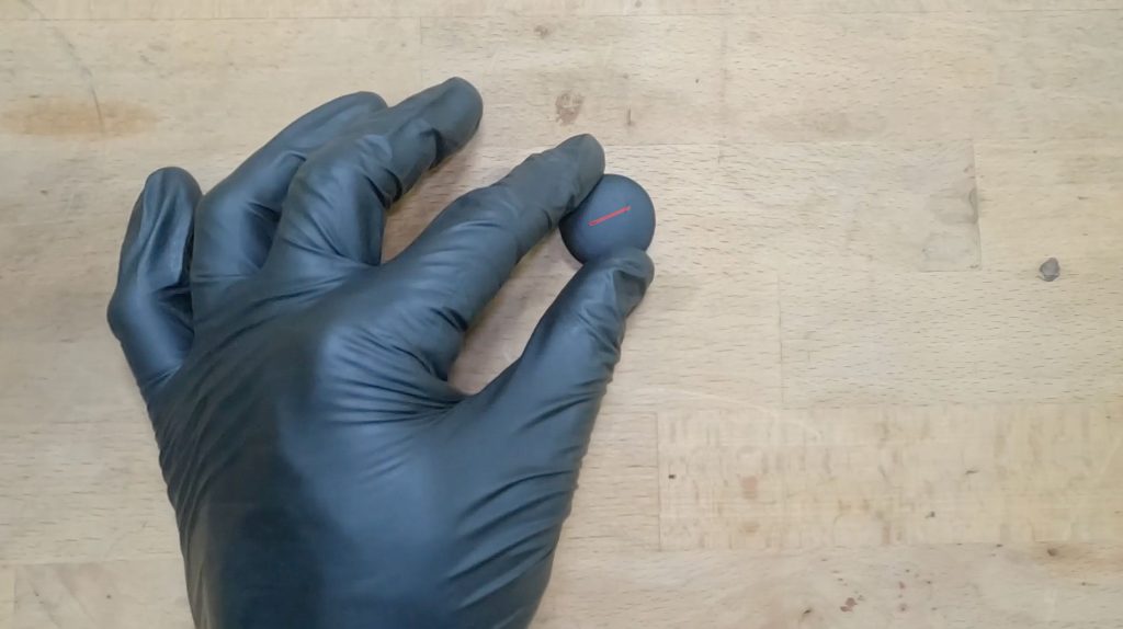
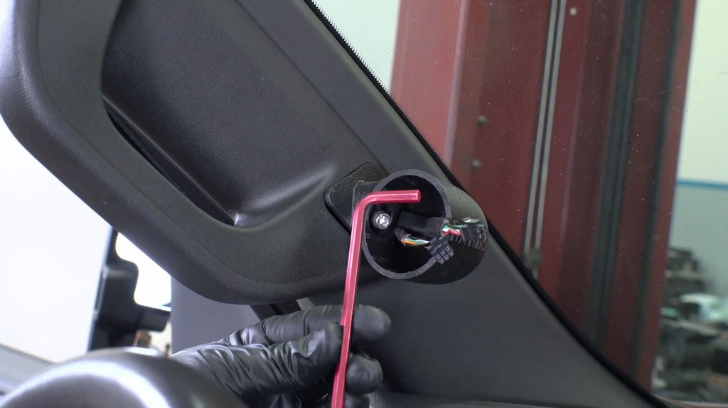
About The Plug
The injector plug has an unusual locking mechanism.
The tab highlighted in red can be both lifted and pushed like a button, as seen in this animation.
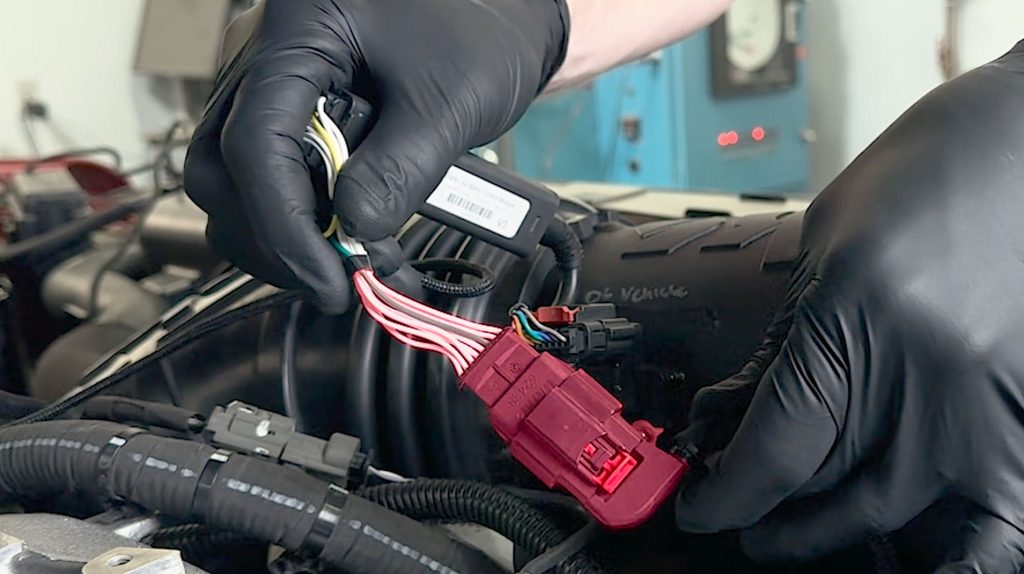
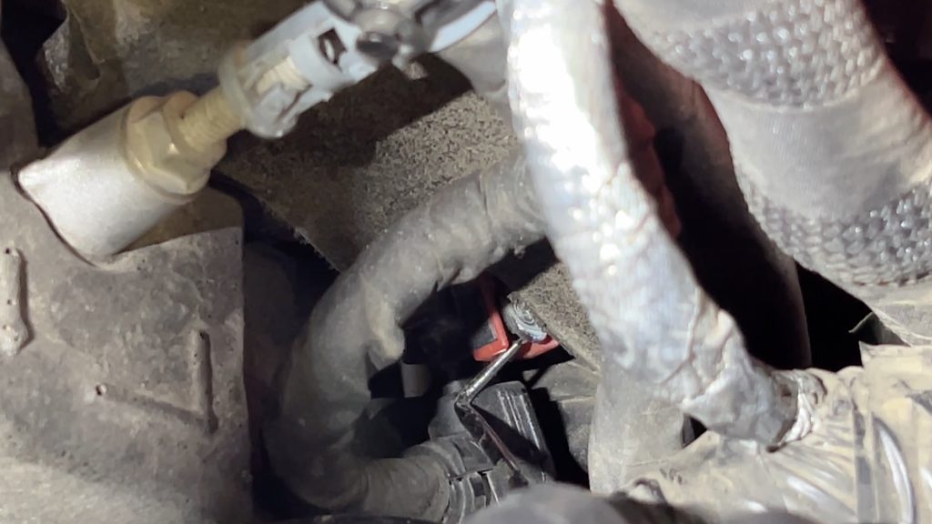
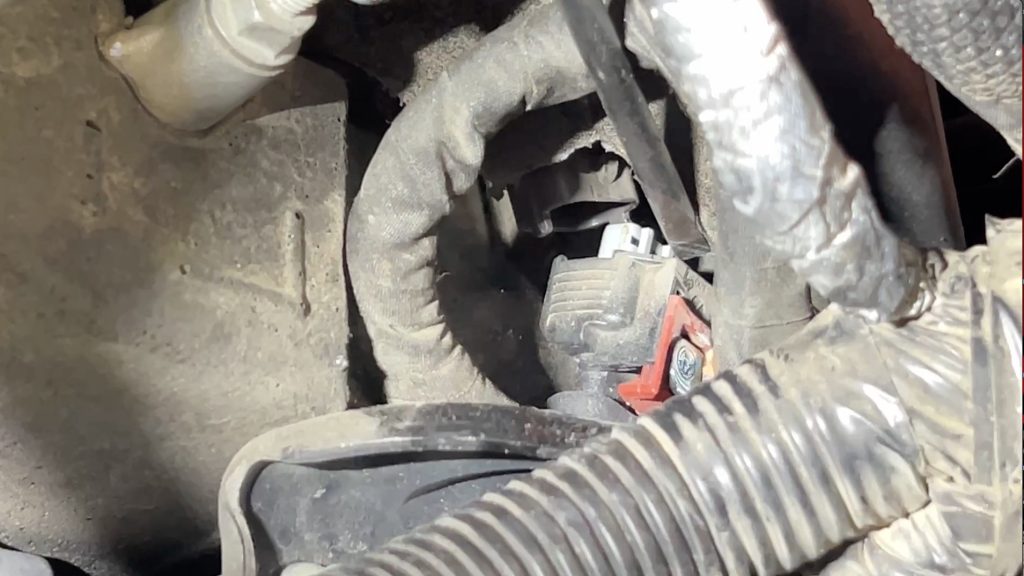
1. Locate the #2 injector located on the driver side valve cover near the front of the truck.
2. First, unplug the harness from the module on top of the valve cover insulator.
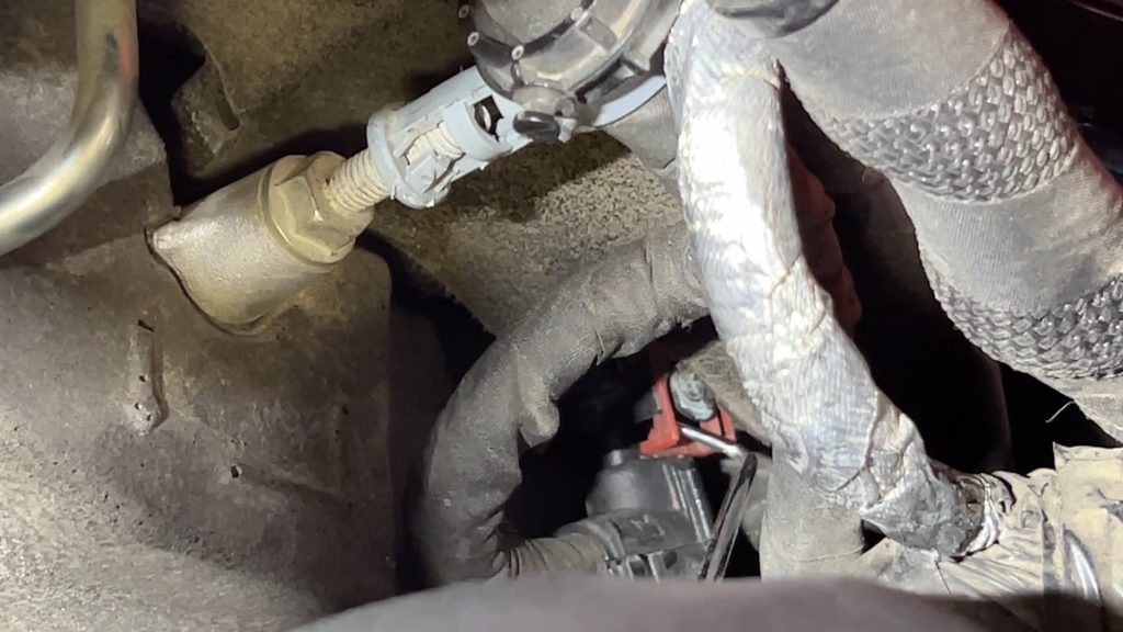
Use a pick to release the red tab and slide the plug off.
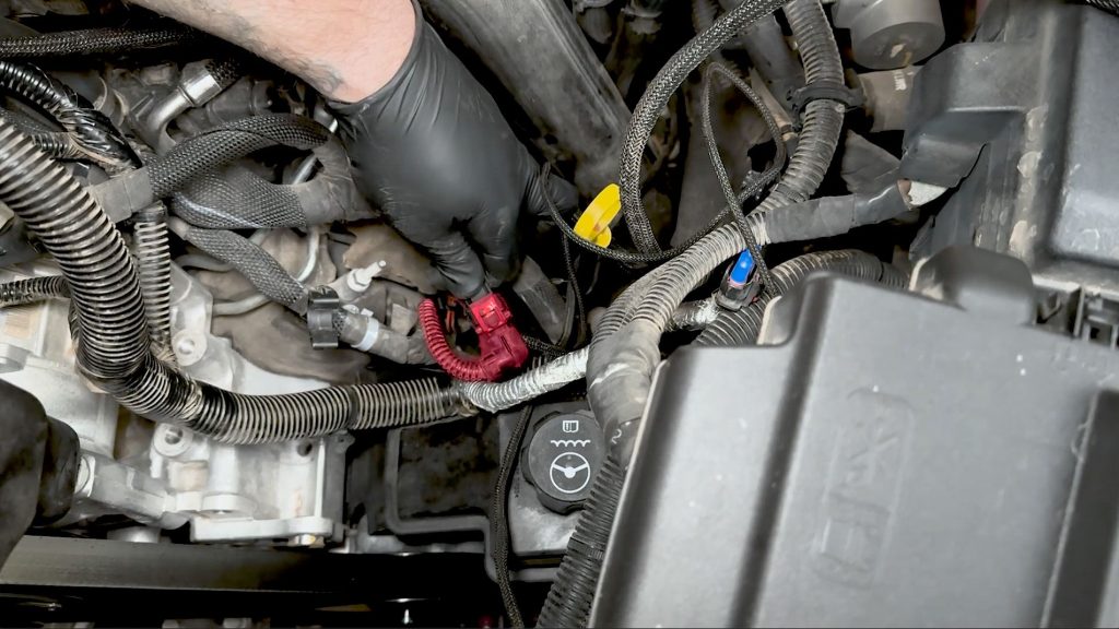
3. With a plastic pro tool, free the harness from the valve cover insulator.
Move the harness up and out of the way.
4. Free the injector harness from the top of the valve cover insulator.
You should now be able to see the #2 Injector.
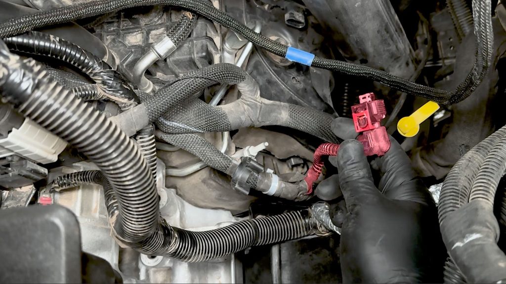
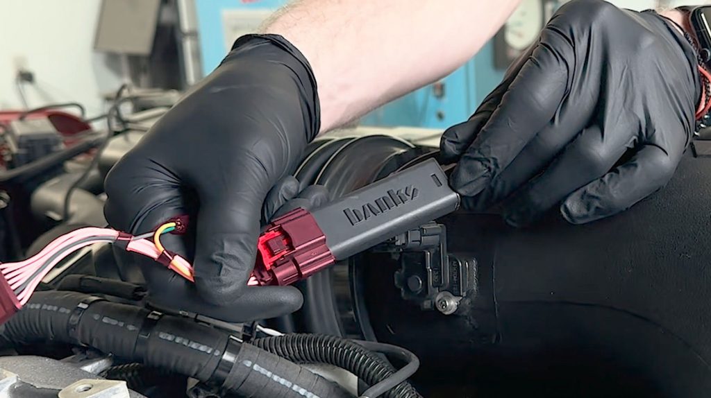
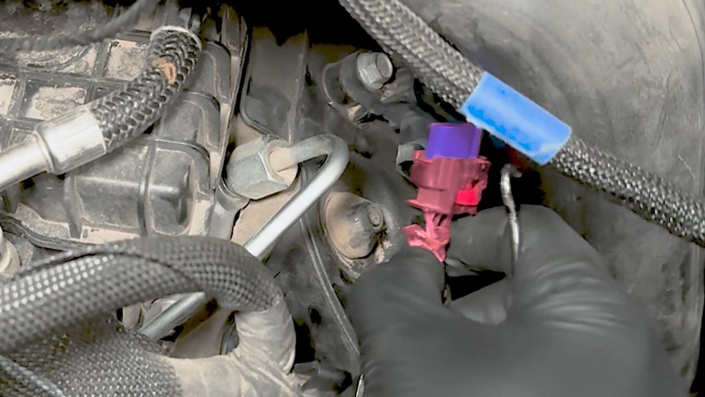
5. Unplug the #2 injector harness.
Intercept the #2 injector with the Banks Derringer harness.
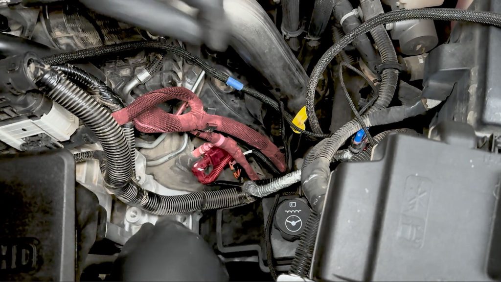
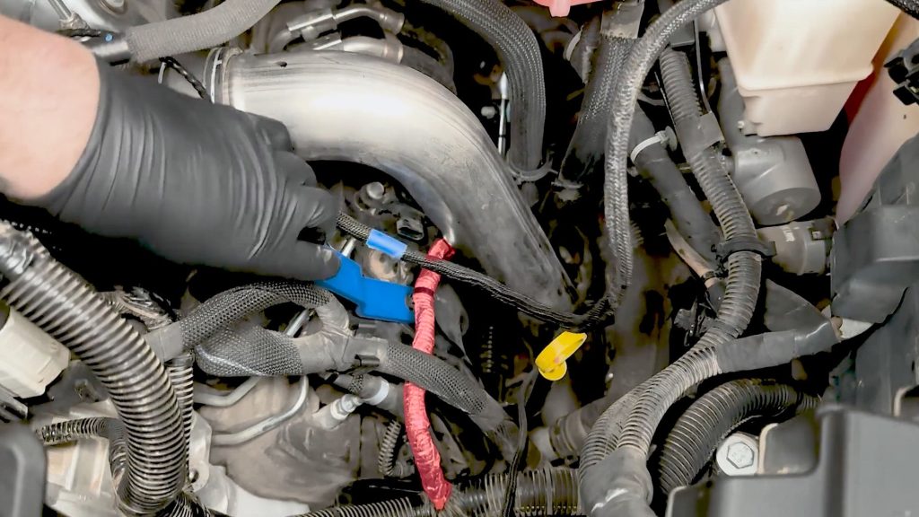
Tuck the injector intercept back down, and re-connect the upper harness to the harness tie downs.
6. Plug the harness back into the module on the top of the valve cover insulator.
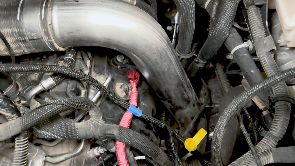
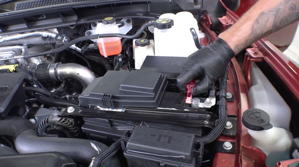
3.0 Derringer Tuner Installation
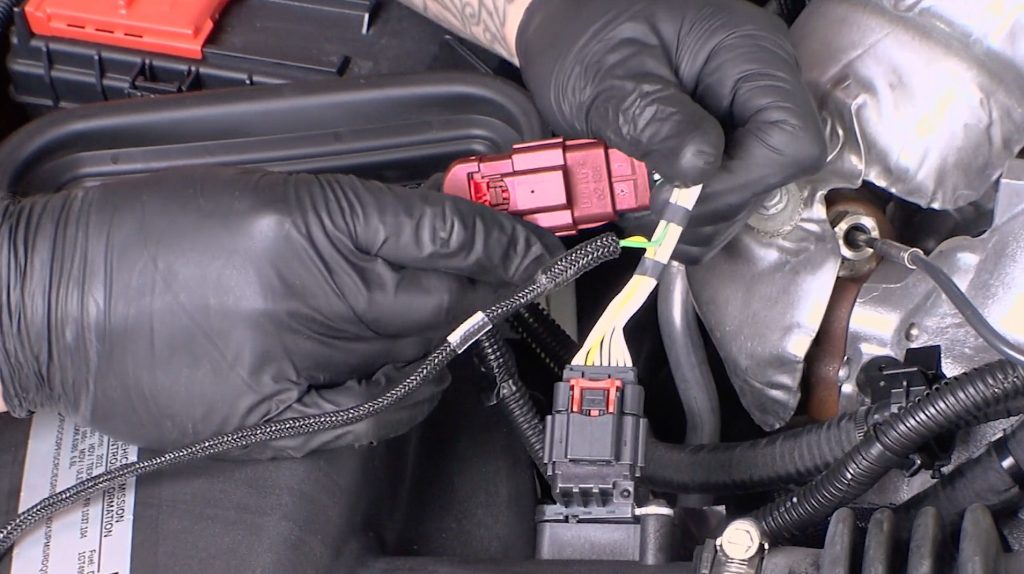
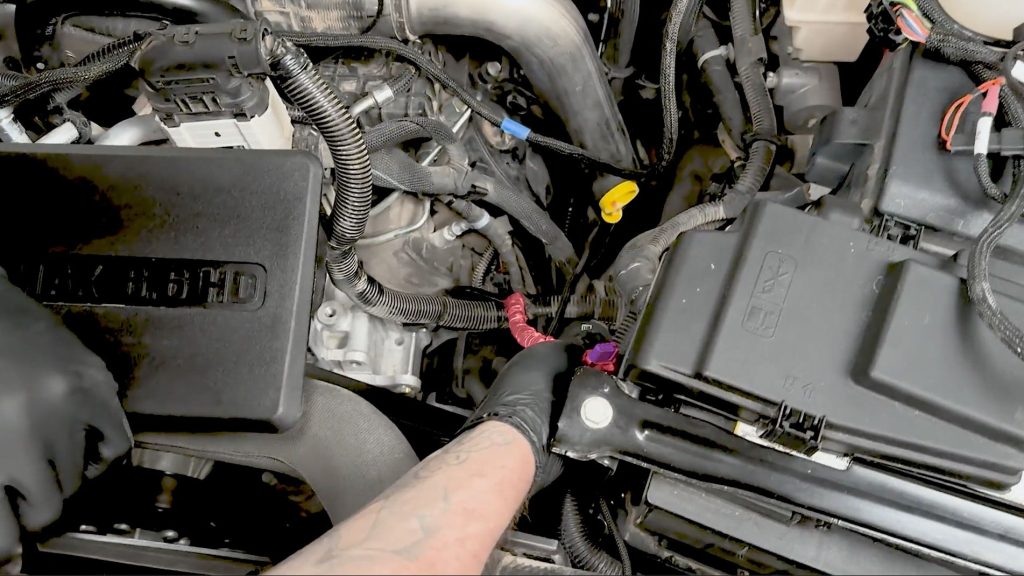
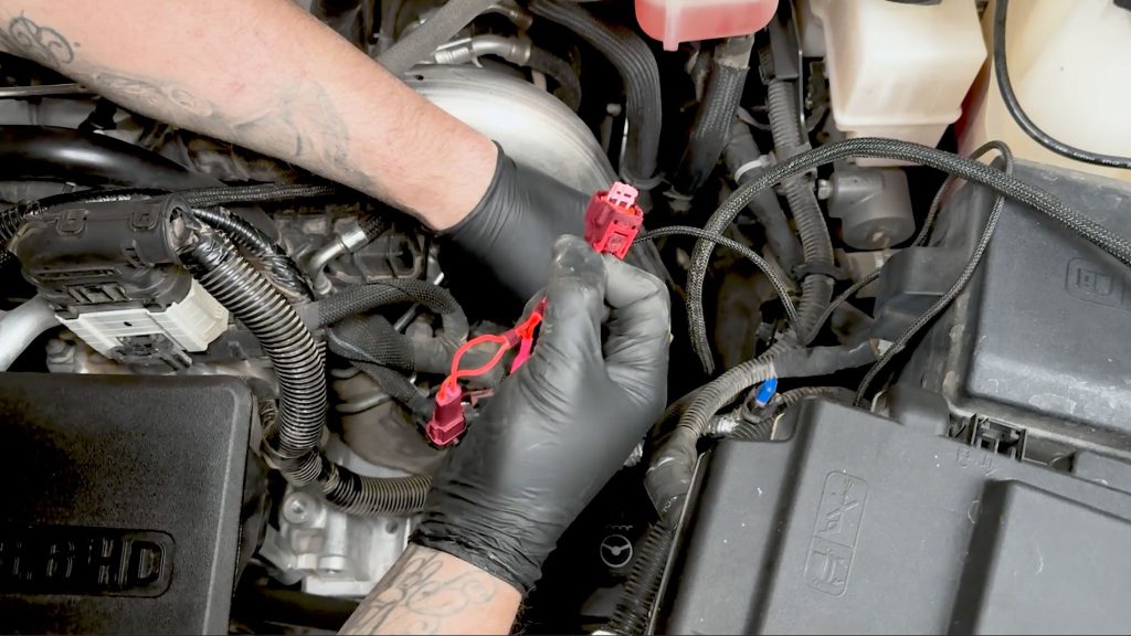
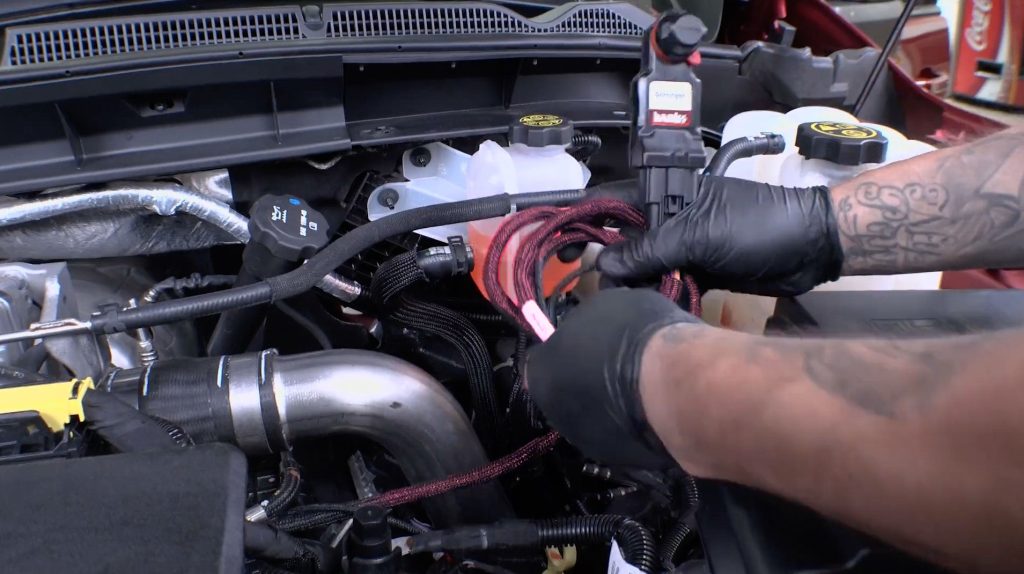
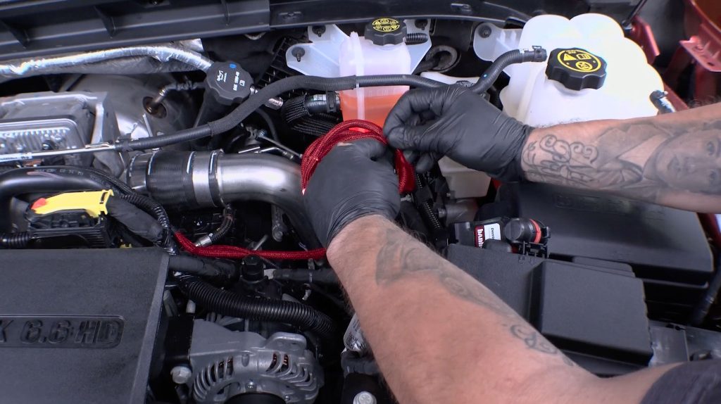
Now that the Derringer harness has intercepted its 4 locations, route the Derringer harness along with the factory harness towards the driver side of the truck. Use the included zip-ties to keep the loom up and out of the way.
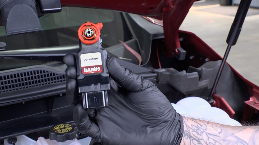
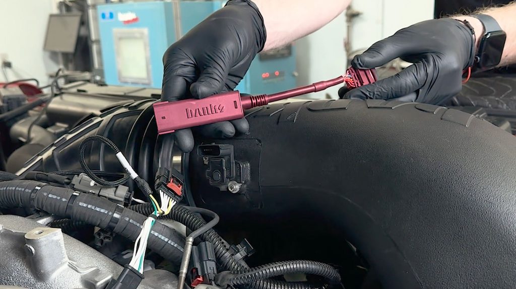
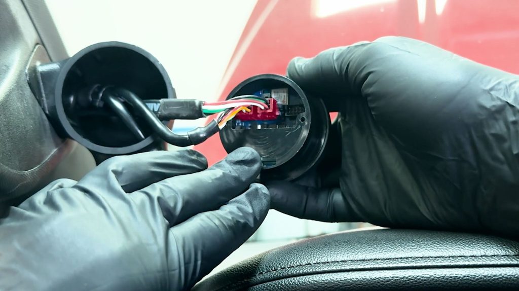
1. Connect the Derringer Module to the black termination cap and sensor intercept harness.

2. Rotate the locking ring so all marks line up at the 12 o’clock position, then connect the mating ends together, ensuring proper alignment using the 12 o’clock marks.
Pushing the pieces together without proper alignment could result in bent pins.
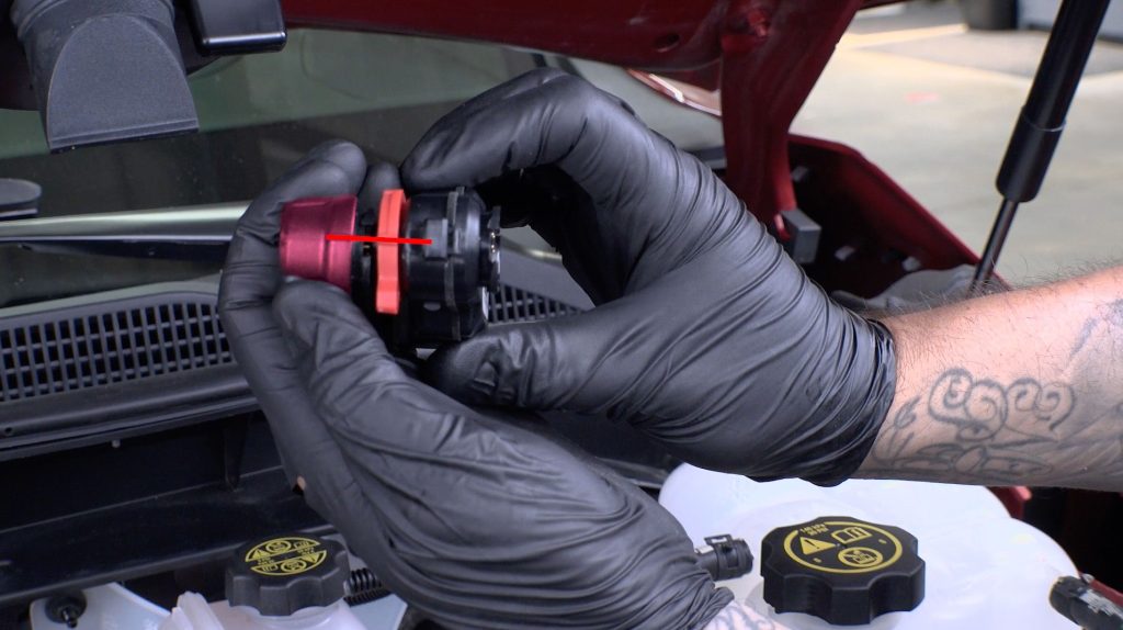
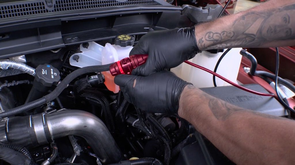
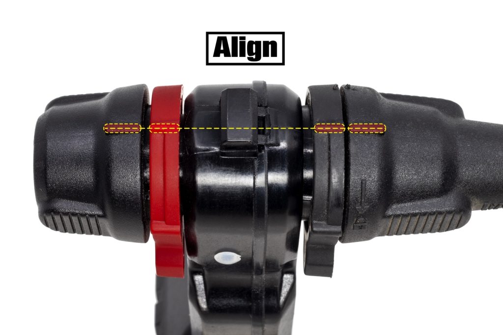
When finished, both the alignment tabs on the cap and starter cable should be directly inline with each other, with the locking rings clicked down.
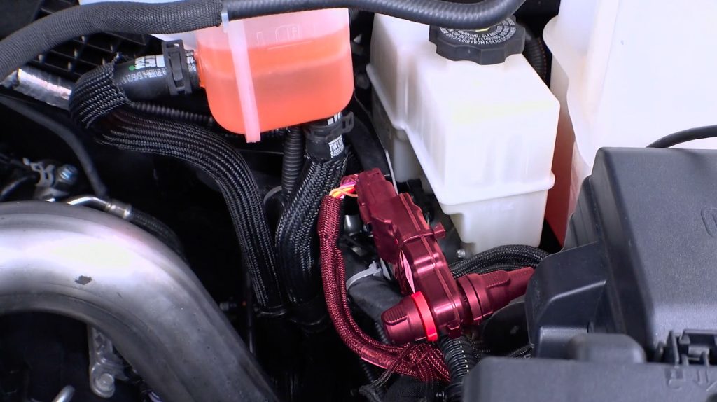
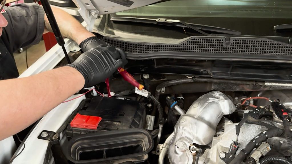
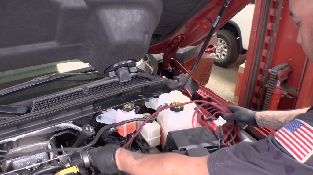
3. Secure the Derringer Module to the factory harness near the brake fluid reservoir
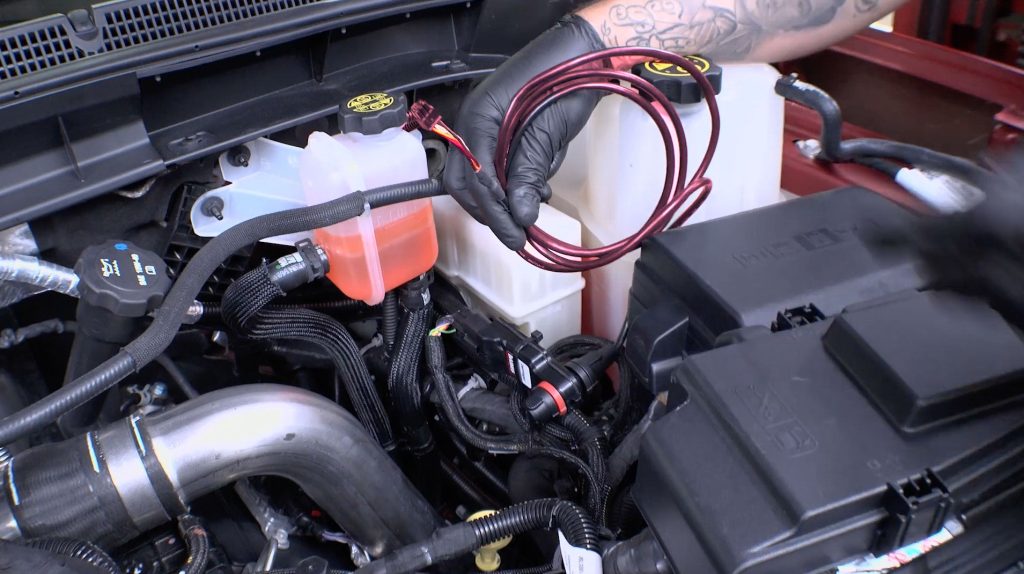
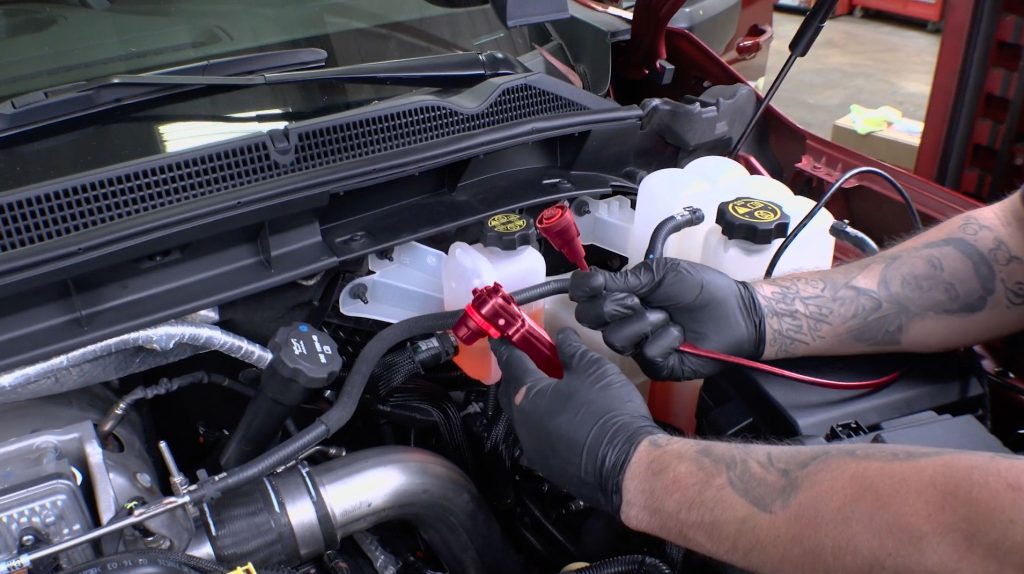
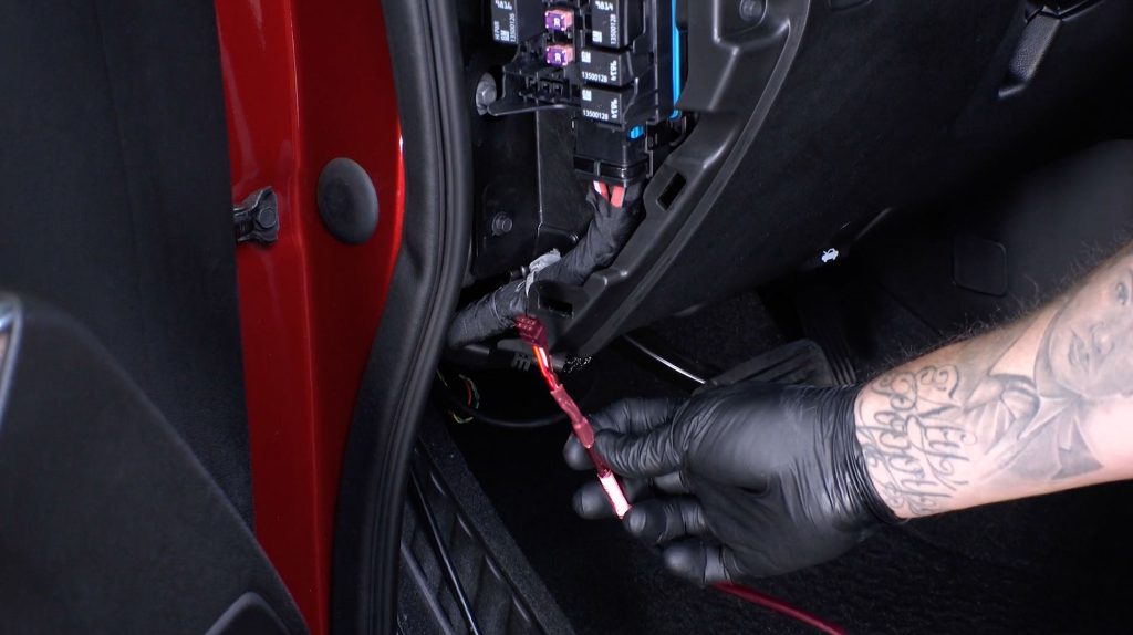
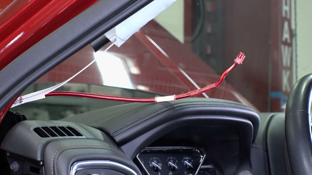
4. Grab the other end of the Derringer Starter Cable, and run it through to the side fender near the driverside door.
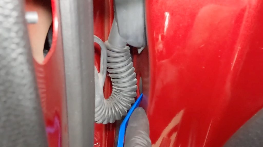
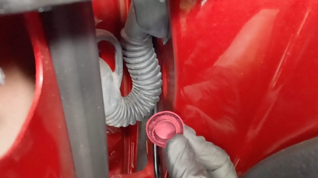
5. With a blade, cut a slice through the grommet to allow your Derringer Starter Cable to pass through.
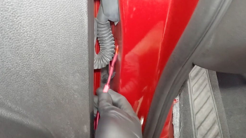
Pull the cable through to the other side. You will need enough slack in the cable to run the 6-Pin Starter Cable up to where you will mount your iDash or into the extra 6-pin port on the PedalMonster if you have one.
4.0 iDash Installation
The following steps show how to install the iDash with a Stealth Pod.
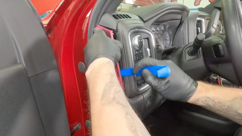
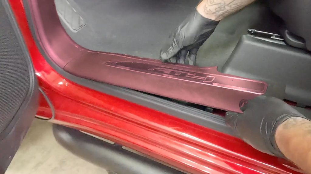
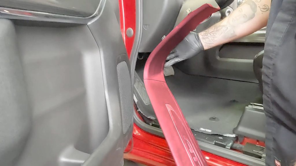
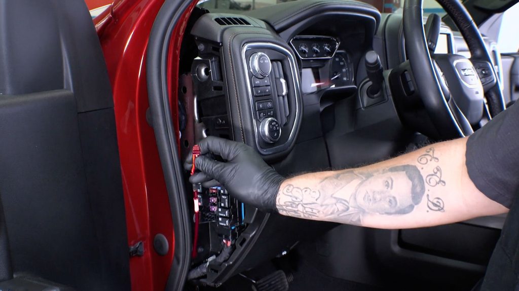
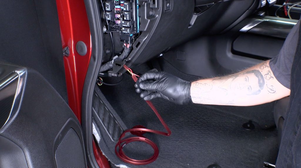
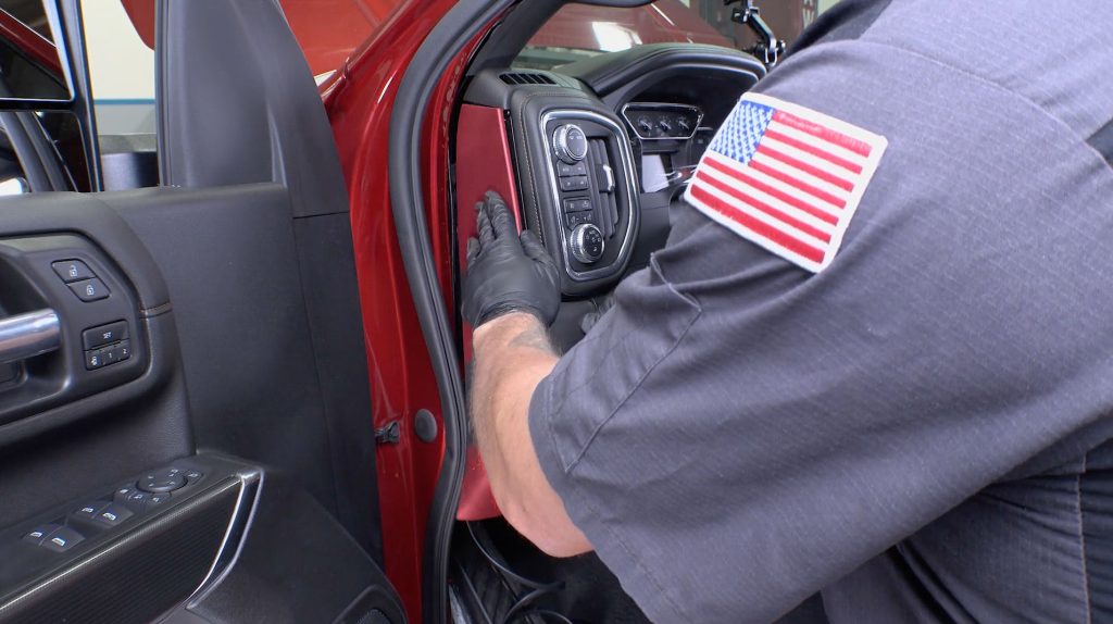
1. Pop the side fuse panel off with a plastic pry tool.
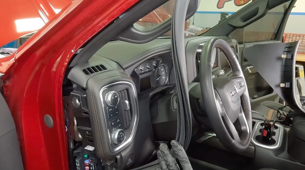
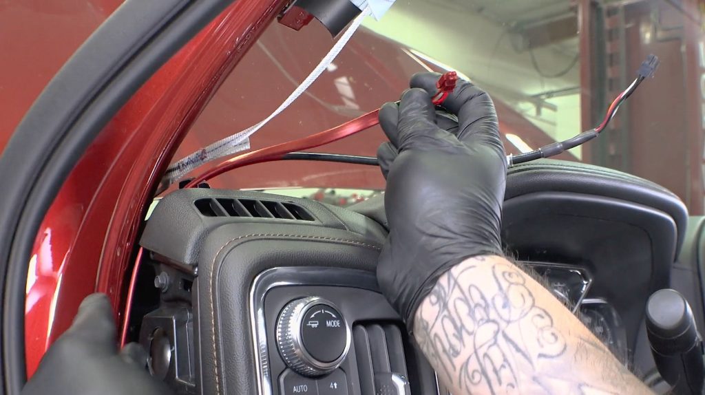
2. Pull back some of the weather stripping around the door frame.
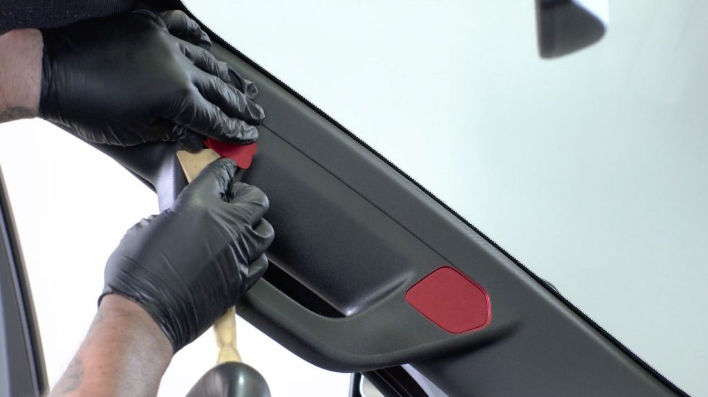
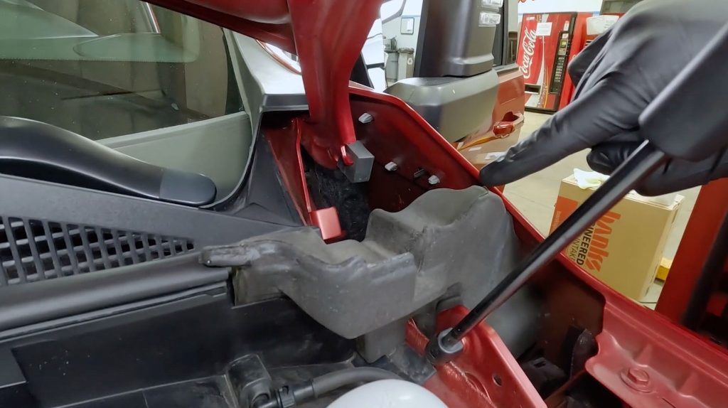
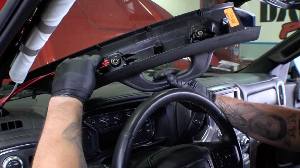
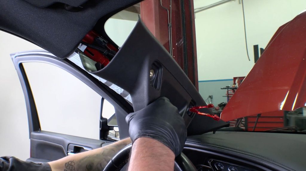
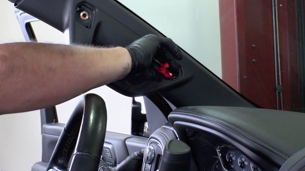
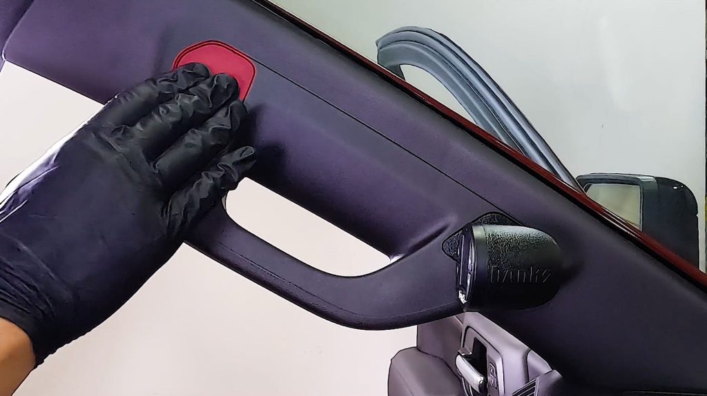
3. With a plastic pry tool, remove the covers over the A-Pillar grab handle bolts.
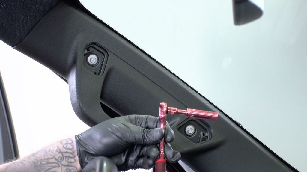
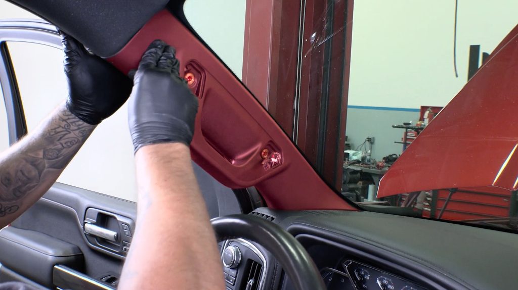
4. With a 10mm socket, remove the two bolts that secure the A-Pillar.
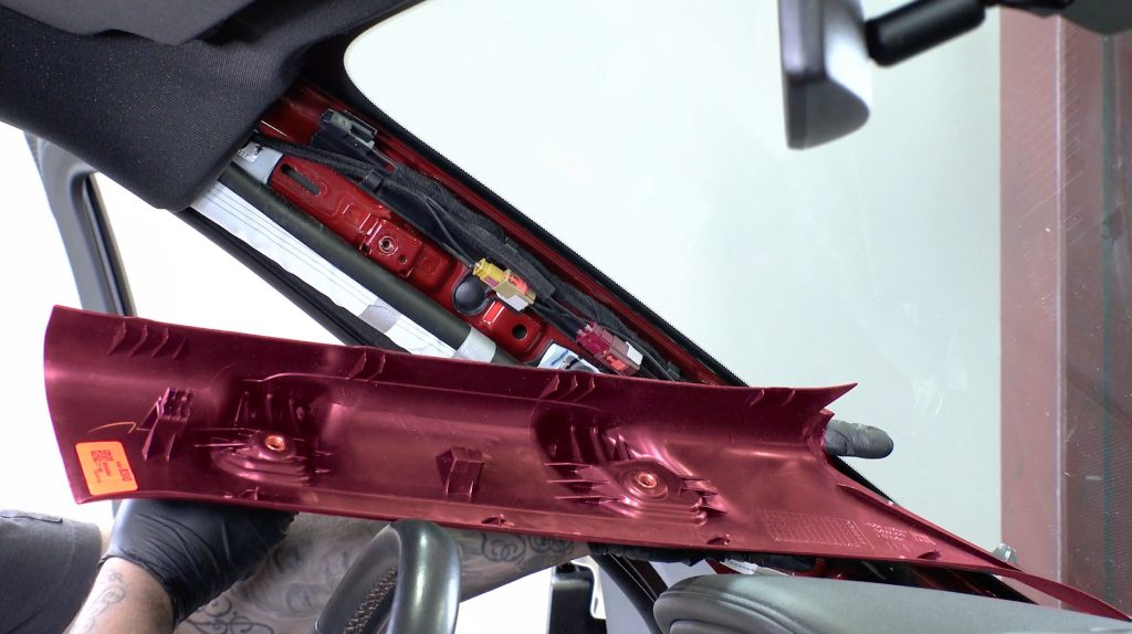
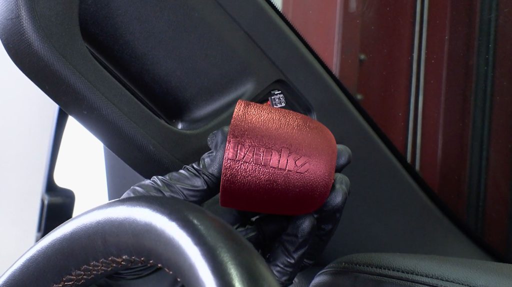
5. With a firm tug, remove the grab handle from the A-Pillar.
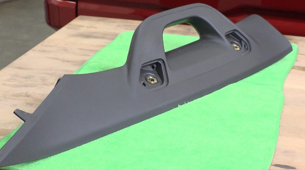
6. Bring the grab handle to a table with a non-slip surface.
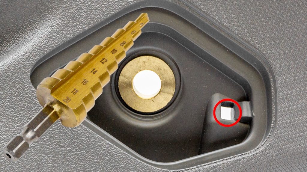
7. With the supplied step bit, you will drill out this hole near the lower bolt.
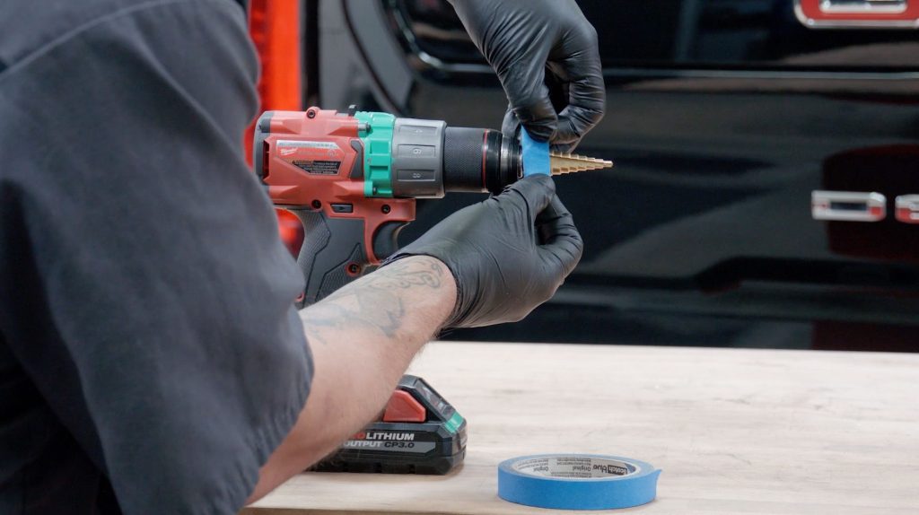
8. You will need to expand the hole to the 18mm mark on the step bit.
Using some painters tape is a good idea to mark the bit so you dont plunge it deeper than you need to.
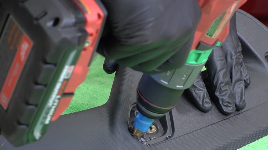
Once you’re satisfied with your hole and have cleaned up any leftover debris, bring your drilled grab handle back to the truck.
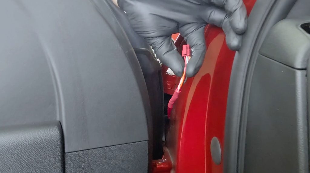
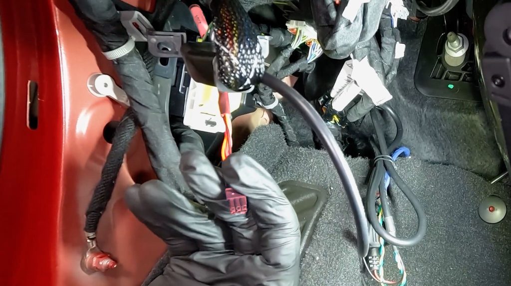
9. If installing a Derringer and iDash only, route the 6-pin Starter Cable up from the bottom and through the side fuse panel. Drape some slack over the dashboard for now.
If installing with a PedalMonster, see below
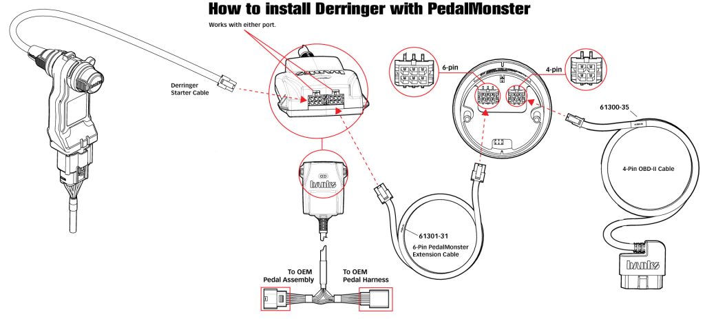
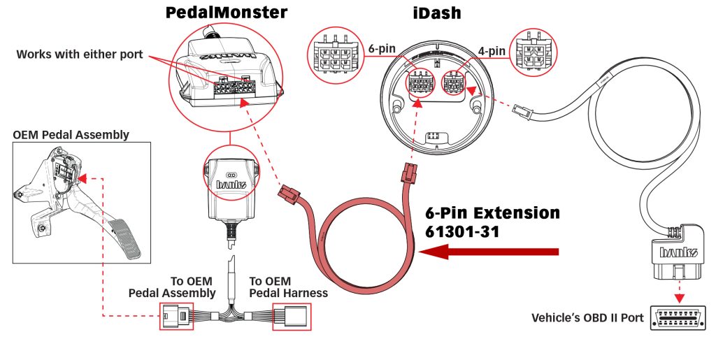
If you already have or will be installing a PedalMonster with your Derringer, the Derringer’s 6-pin Starter Cable will plug directly into one of the extra ports on the PedalMonster down by your feet and not directly into the iDash.
Then route a 6-Pin PedalMonster Extension Cable (61301-31) up from the PedalMonster and into the 6-pin port on the back of the iDash instead.
10. Route both cables through the hole you drilled into the grab-handle.
11. Snap the grab-handle back onto the A-Pillar.
12. Grab your Stealth Pod and run the wires through the cable access hole in it.
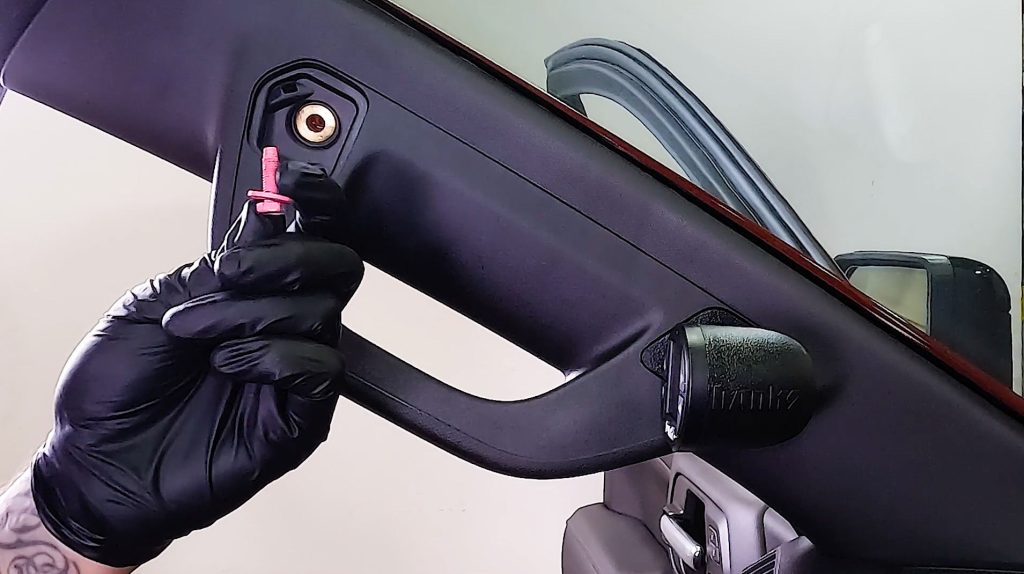
13. Starting by hand, thread in the supplied hex head bolt and washer, secure it with the supplied key.
14. Connect the 6 pin Derringer and 4 pin OBD-2 cables to the ports on the back of the iDash.
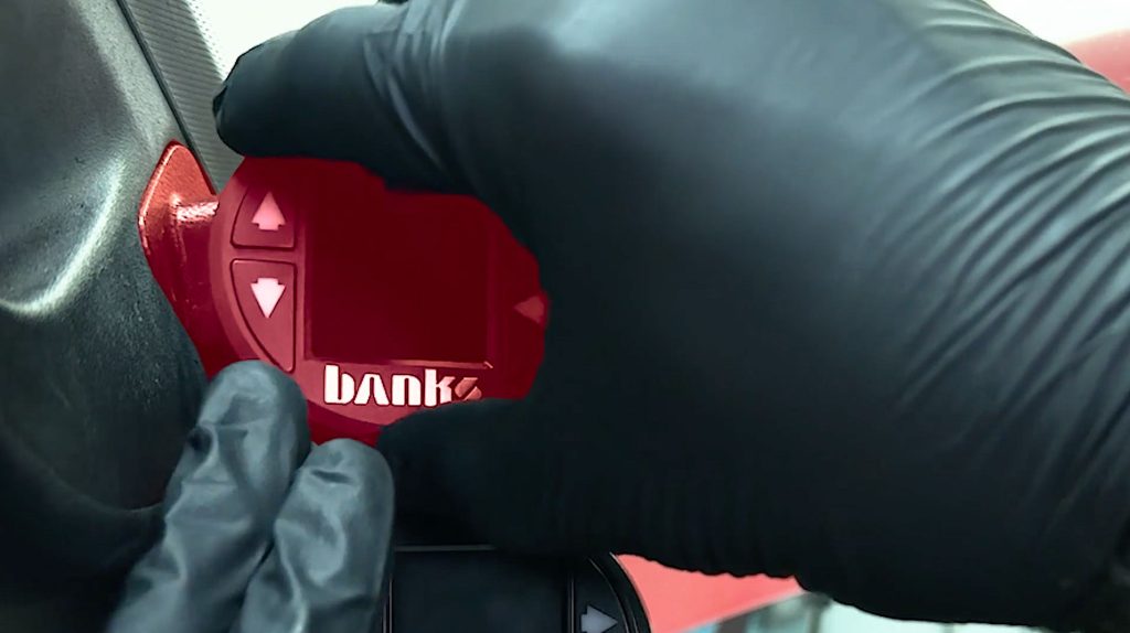
15. Slide in your iDash and make sure the banks logo is straight and level.
16. Secure the top bolt with a 10mm socket.
17. Snap back in the top cover for the bolt.
18. Snap back in the side fuse cover.
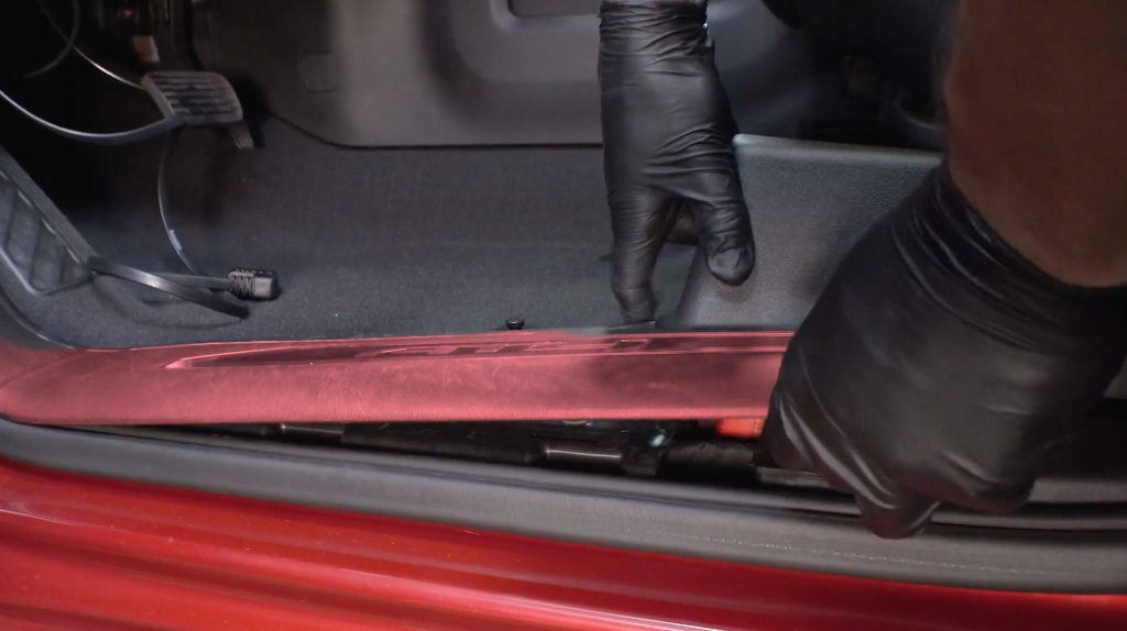
19. Snap back in the lower kick panel.
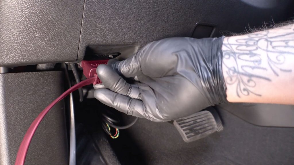
20. Connect the Banks OBD-2 cable to the OBD-2 port under the dash board.
21. Tidy up any excess wire and tuck it up and out of the way.
22. Reconnect the negetive battery terminals in the engine bay.
23. Check that the iDash powers up with the truck, and that a green status light is illuminated on the Derringer Module in your engine bay.
24. Let’s check your installation. If the ECU was properly powered down prior to installation, upon starting the truck for the first time, you should not experience a check engine light or any errors on the dashboard. If a check engine light or any errors are present, use the iDash to clear the codes. Proceed to step 24.1.
24.1 While the engine is running, in Park, follow these steps to clear codes using the iDash.
a. Right arrow to enter menu
b. Scroll down to highlight Diagnostics
c. Select Diagnostics using right arrow
d. Scroll down to Vehicle
e. Select Vehicle using right arrow
f. Scroll down to Clear Vehicle Codes
g. Use right arrow again to confirm Clear Codes
h. Wait for Clearing Codes message to disappear
i. A message will display: Codes Cleared
j. Turn off ignition and wait until dashboard fully powers off.
k. After dashboard powers off, restart engine. All errors should be gone.
l. If errors persist, contact Banks Tech Support by phone or text.
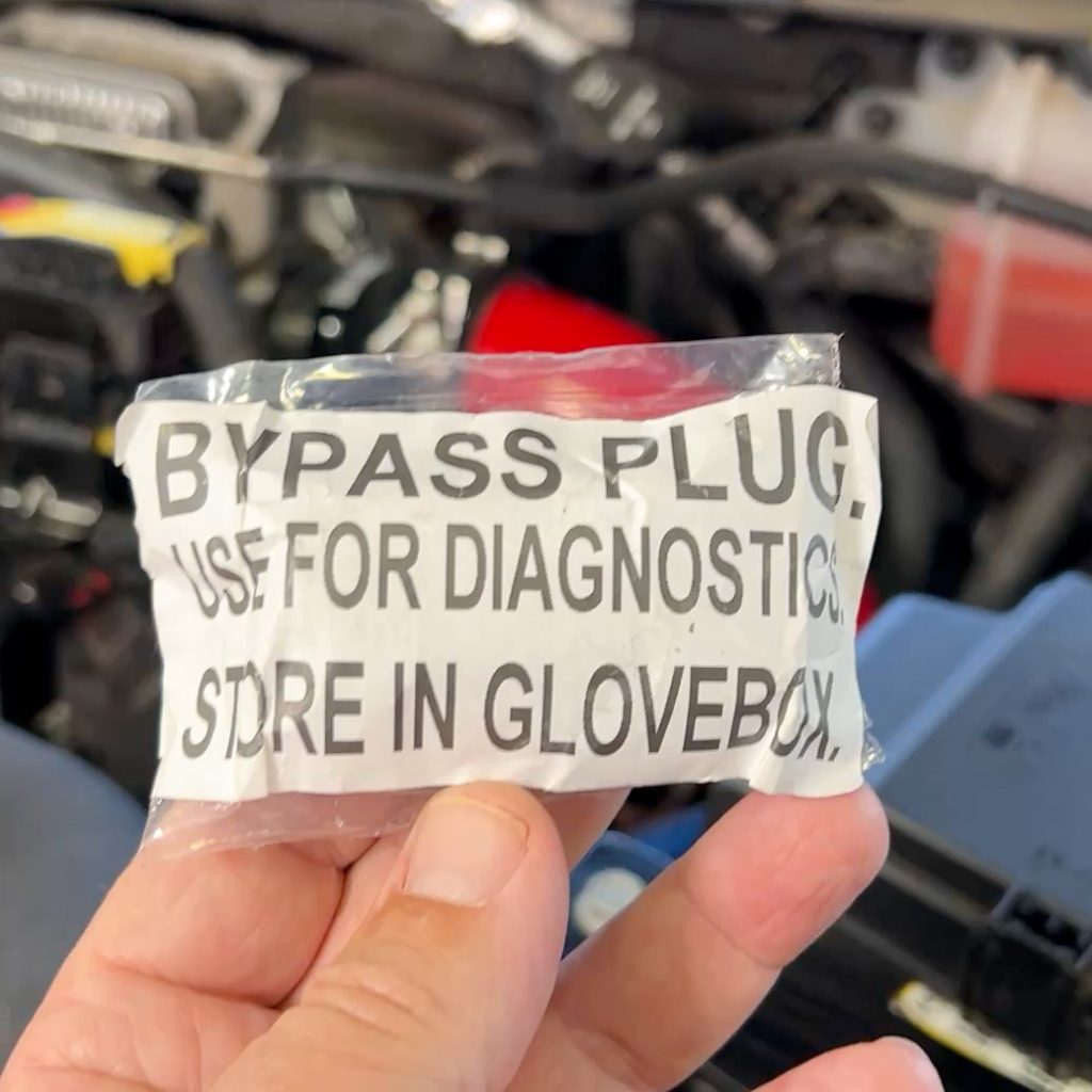
m. If after hours, and Tech Support is not available, install supplied Banks Bypass Plug
n. Remove engine harness connection from bottom of Derringers module
o. Install Banks bypass plug onto Banks engine harness
p. Repeat code-clearing process.
5.0 Derringer settings and configuration
5.1 Checking your connection
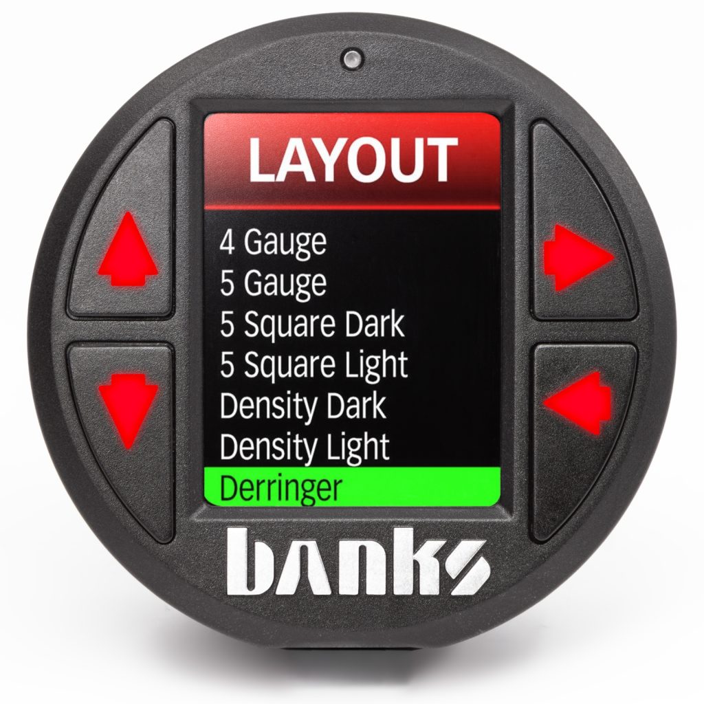
On the iDash, navigate to the Gauge Layout, scroll down, then select the “Derringer” layout. Using the UP and DOWN arrow buttons to adjust the power level settings.
If the power level cannot be adjusted, refer to “Section 6: Troubleshooting”
5.2 Derringer Tuner Operation
Setting Desired Power Level:
The Derringer is equipped with multiple power levels. You can set the desired power level while driving, however, it is recommended that you do not switch the power level under high load applications.
iDash configuration:
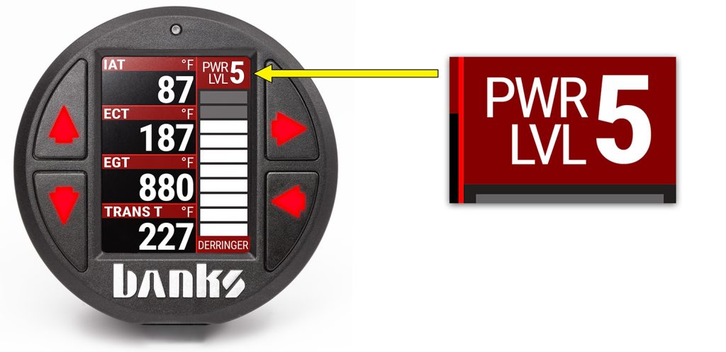
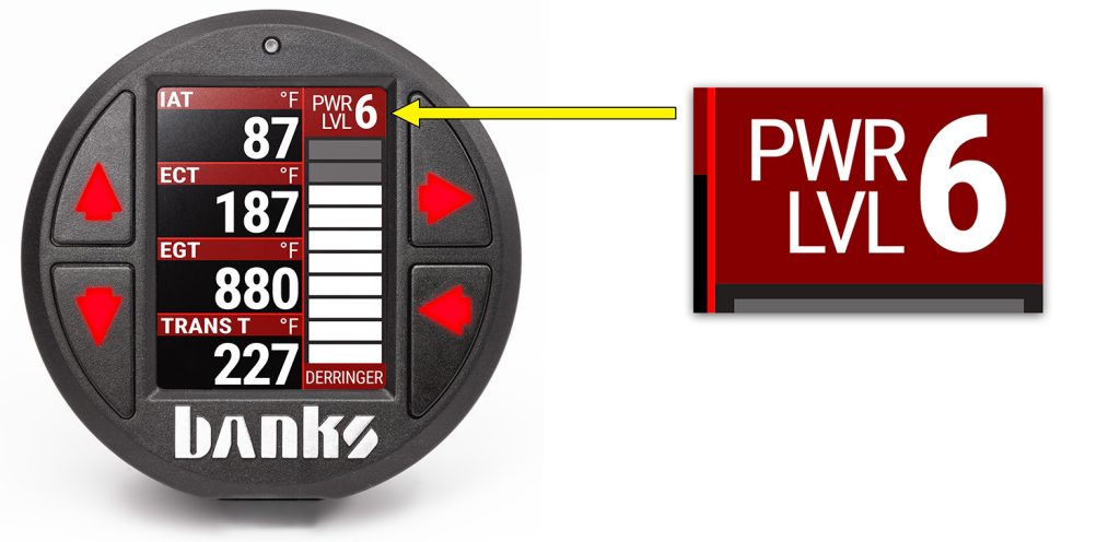
When the Derringer is connected to an iDash, there are a total of 6 power levels (level 6, 5, 4, 3, 2, and stock). The power level can be changed by pressing the UP and DOWN buttons at any time. If you have the Derringer layout loaded, you will see the power level change at the top right corner. If you have any other layout loaded, a message box will pop up to notify you of the power level change.
SPORT MODE/LEVEL 6
This mode is to be used when peak engine performance is desired. This mode has been optimized for maximum power output along with improved turbo response by tuning fuel delivery and boost.
PLUS MODE/LEVEL 3
The plus calibration is designed for use in everyday driving. This power level adds a noticeable punch under high load acceleration by improving turbo response and power. Power in this mode can be sustained for a prolonged duration.
STOCK MODE
Stock mode turns OFF your Derringer tuner. Throttle response and power return to stock levels.
Banks ActiveSafety®
Anytime aftermarket electronics are introduced to your vehicle, it is important to know that they are not going to cause damage. Banks builds in a suite of ActiveSafety features to safeguard your vehicle:
» Software that monitors and diagnoses itself to ensure proper function.
» Self-monitoring hardware that provides automatic bypass should something malfunction.
The Derringer Tuner module monitors multiple parameters and adjusts its output controls to protect the driveline. The Derringer Tuner monitors engine coolant temperature (ECT) and will limit the additional power that it provides anytime the ECT is outside of optimal operating range to protect the engine.
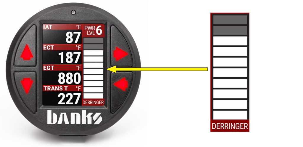
Power Added (%):
When connected to an iDash while displaying the “Derringer” layout, the vertical bar graph on the right-hand side represents, in real-time, how much power the Derringer is adding. In Stock Mode there will be no change to the bar graph and in Sport Mode/Level 6 the bar graph will reach 100% under proper operating conditions. Percent power added is affected by safety features such as Engine Coolant Temperature, Exhaust Gas Temperature, Regen., and various transmission parameters, so it might not always fully reach 100%. The “Power Added” data can also be displayed on ANY layout as a numeric value by selecting it from the “Derringer” category of parameters.
Automatic Transmission Learning:
6.6L GM Duramax pickup trucks equipped with the Allison 10L1000 10-speed automatic transmission use an adaptive shift control logic. After the initial installation of the Derringer Tuner, wide-open throttle shifts may feel soft when switching to higher power levels. Also, when switching to lower power levels, shifting may feel harsher. Continued use at a single power level will provide more consistent shifting performance.
To accelerate the learning process perform the following sequence at a location where it is safe to accelerate without exceeding the posted speed limit.
1. Set the Derringer Tuner to Stock Mode power setting, start the truck and allow the engine to reach normal operating temperature.
2. Adjust the Derringer Tuner to Plus Mode/Level 3 power setting.
3. Drive your vehicle for 5-10 miles, ensuring a complete shift cycle through each gear (The transmission shift learning process requires 15-30 complete shift cycles to learn a new shift program).
4. Increase power level to Sport Mode/Level 6 and repeat Step 3.
6.0 Troubleshooting
No Communication with iDash
Check that your wiring matches the figure in Section 1.0 Wiring Diagram: Derringer High Output Tuner System, Configuration..
Common sources of Derringer communication errors (D-ERR) are wrong caps attached to the Derringer and/or the In-Cab Termination Cable is not installed. A Black Termination Cap must be connected to the Derringer and only one In-Cab Termination Cable should be attached to one of the iDash units.
iDash Display Error Code
If error code “D-ERR!” appears on the iDash, refer to the following to display the code and description:
Settings > Diagnostics > Select the module that is giving the error
Derringer Tuner (GM L5P application)
| Event | Course of Action |
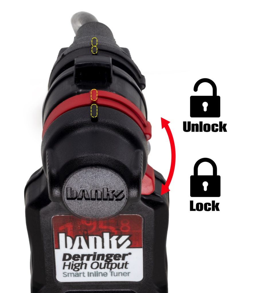
| Derringer not detected by iDash | Press the right arrow to enter the menu. Use the down arrow to scroll to Banks Modules. If Derringer is displayed, proceed to stop 5.2. If Derringer is not displayed, scroll to and select Re-Scan for Modules using the right arrow. At the Derringer, rotate the locking ring to the unlocked position on the Starter Cable side. Separate starter cable from Derringer. Inspect all 6 gold pins on Derringer to ensure they are not bent. Reconnect Starter Cable, ensuring orientation is correct. Make sure Starter Cable is fully seated into the Derringer. Then, rotate locking ring into locked position. Do not rely locking ring to seat the cable into the Derringer. |


CARB EO Label
For smog check purposes, affix the CARB E.O. Label on a visible location under the hood. Banks recommends using the radiator shroud location.
Technical Support
If you require support, call or text (800) 601-8072 during normal business hours, Monday-Friday. We can also be reached via Facebook messenger.