


97707 – Intercooler Upgrade Kit for 2011 Chevy/GMC 2500/3500 6.6L Diesel
The video install above shows an install on a 2012-2016 Duramax 6.6L. While the 2011 model year features a two-piece hot-side boost tube, the installation process is the same otherwise.
General Installation Practices
1. Before starting work, familiarize yourself with the installation procedure by reading all of the instructions.
2. Throughout this manual, the left side of the vehicle refers to the driver’s side and the right side to the passenger’s side.
3. Disconnect the negative (ground) cable from the battery (or batteries, if there are more two) before beginning work.
4. Route and tie wires and hoses a minimum of 6″ away from exhaust heat, moving parts, and sharp edges. Clearance of 8″ or more is recommended where possible.
5. When raising the vehicle, support it on properly weight-rated safety
stands, ramps, or a commercial hoist. Follow the manufacturer’s safety
precautions. Take care to balance the vehicle to prevent it from slipping or
falling. When using ramps, be sure the front wheels are centered squarely on the topsides. When raising the front of the vehicle, put the transmission in park (automatic) or reverse (manual), set the parking brake, and block the rear wheels. When raising the back of the vehicle, be sure the vehicle is on level ground and the front wheels are blocked securely.
Caution! Do not use floor jacks to support the vehicle while working
under it. Do not raise the vehicle onto concrete blocks, masonry, or any other item not intended specifically for this use.
6. During installation, keep the work area clean. Do not allow anything to
be dropped into the intake, exhaust, or lubrication system components while performing the installation, as foreign objects will cause immediate engine damage upon start-up.
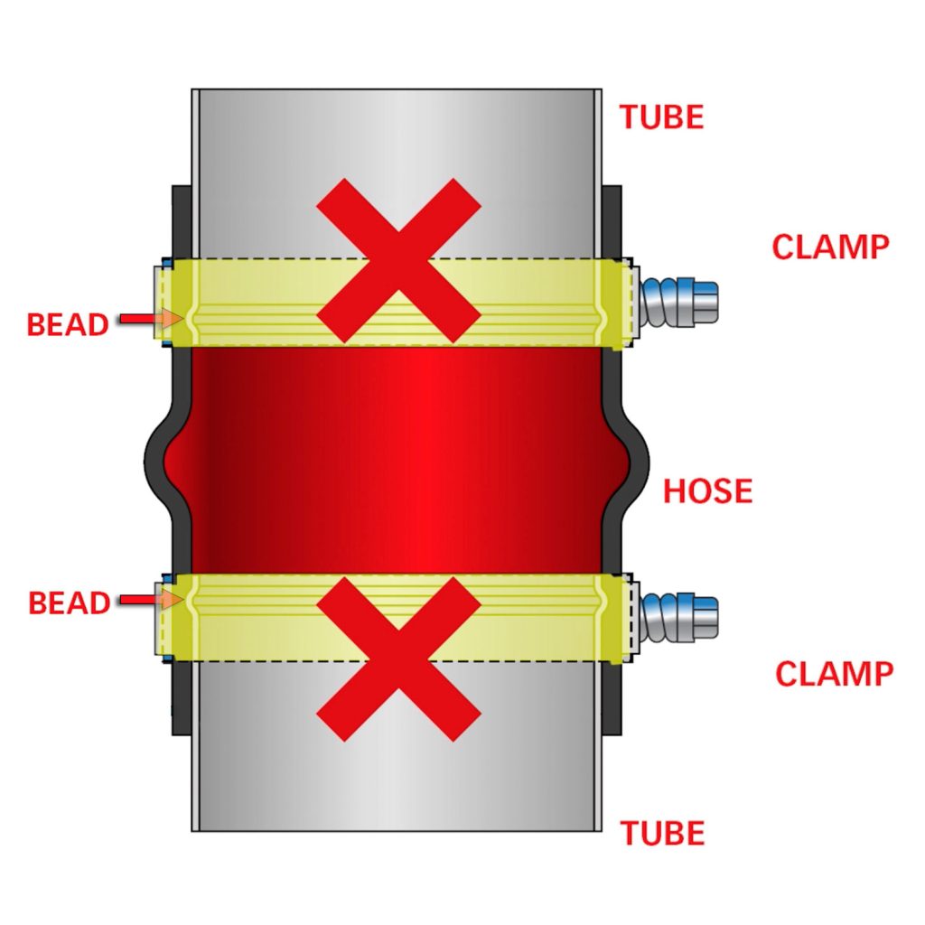
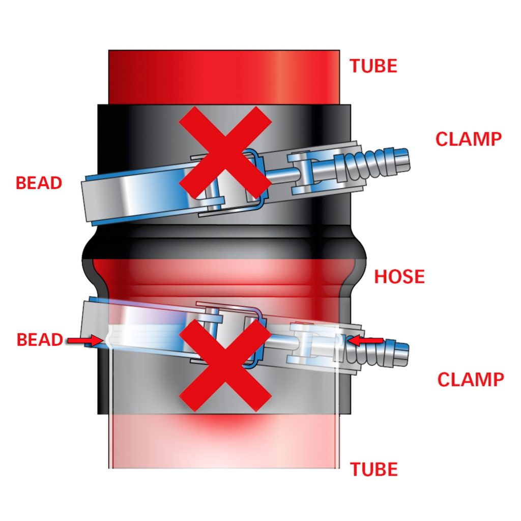
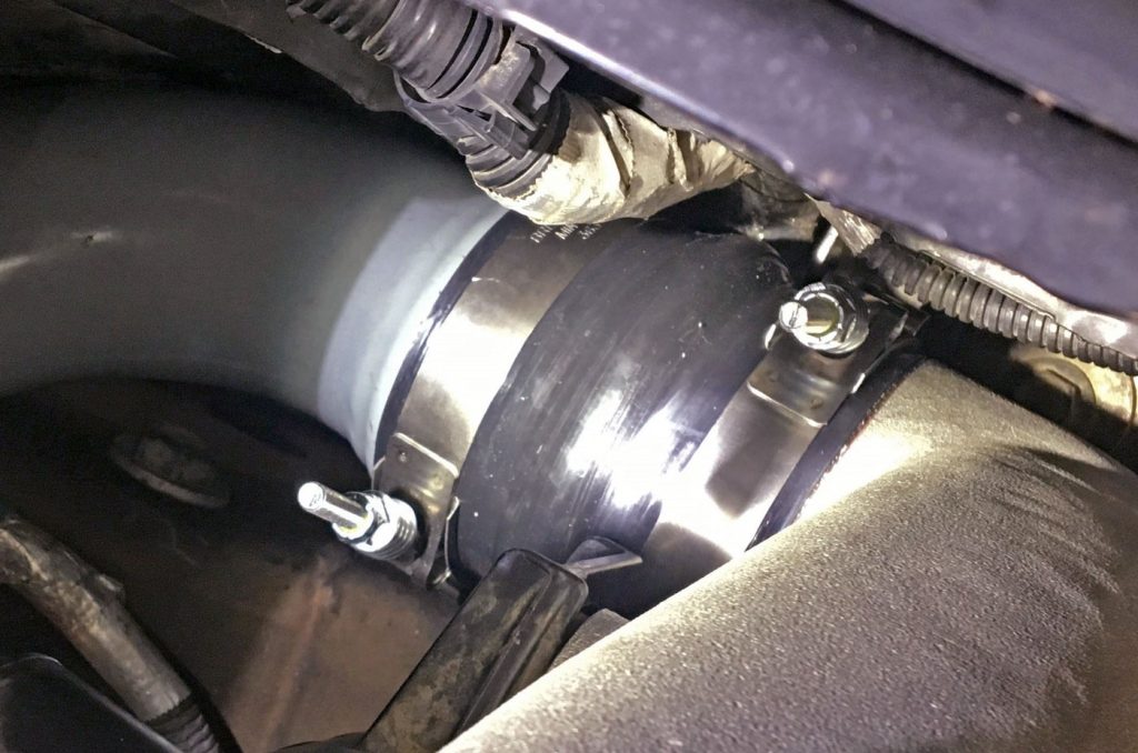
ATTENTION: Boost-Tube Clamps
When Installing the clamps, be sure the hose and clamps go on far enough to clear the bead on each end.
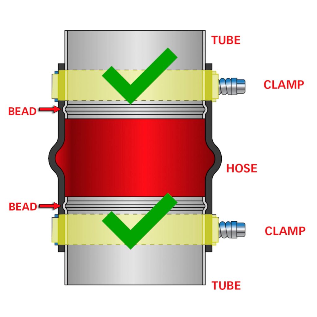
An improper installation, such as a clamp sitting directly on a bead or crossed diagonally, will result in a boost leak.
Section 1: General Assembly
Section 2: Removing Stock Intercooler
Step 1
Disconnect the ground cables from both the driver and passenger side batteries. Position the loose cables so that they do not come into contact with their respective battery posts during the installation.
Step 2
Remove the air box filter assembly. Loosen the hose clamp from the stock
intake tube and separate the stock intake tube. Remove the Air Flow (MAF) sensor connector from the stock airbox filter cover. Remove the stock airbox by lifting the airbox up and out. The bottom of the stock airbox is held in place by rubber grommets. There may be some slight resistance when removing the stock airbox.
NOTE: Be careful not to damage the connector or the MAF sensor.
NOTE: The number of sensors may vary with the model year.
Step 3
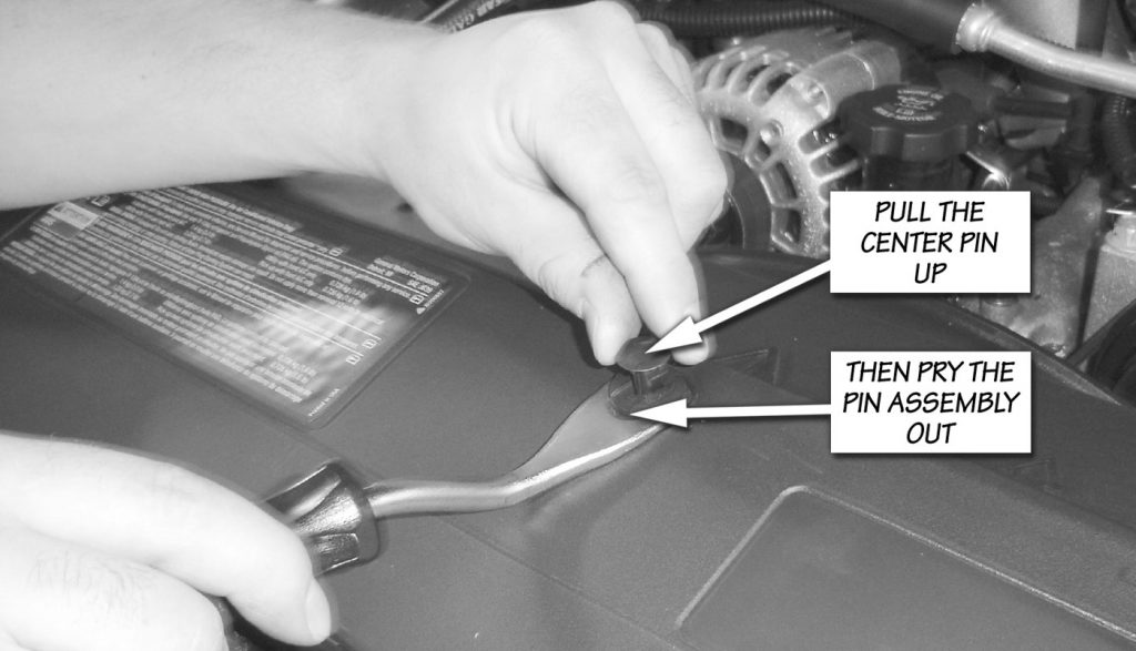
Remove the upper grill baffle. Remove the upper grill baffle that
mounts between the grille and radiator cross brace. The baffle is held in place by push-in retainers. The retainers are removed by pulling up on the center pin, then prying the retainer out of its hole as shown in Figure 1.
Step 4
Remove the front grille. Pull the grill gently outward until all clips are disengaged.
NOTE: Some model years may vary. Be sure to remove any bolts holding grill first.
Step 5
Remove the inner fender well. Remove the pushpin fasteners and bolts from both driver’s and passenger’s side fender well.
NOTE: The fasteners are accessed through the wheel arch opening. Pull the fender well down approximately six inches once the fasteners are removed. Disconnect the wire harness retaining clips on top of the fender well, and then remove the fender well from the vehicle.
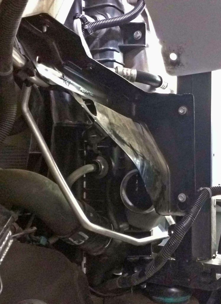
Step 6
Remove both diagonal fender support braces. See Figure 2.
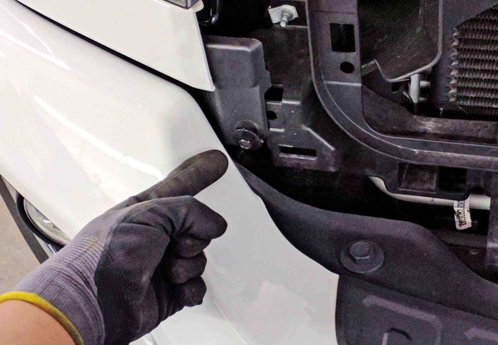
Step 7
Remove the trim panel below the headlight. See Figure 3.
Step 8
Remove three 10mm bolts from headlamps. Pull the top of the lamp down and carefully forward. Disconnect headlamp harness from the backside of the headlamp assembly, and remove both drivers and passenger headlamp assemblies from the vehicle.
NOTE: The headlamp os easily disengaged and does not require force.
Attention: The number and location of bolts on the headlamp assembly may vary by model and year.
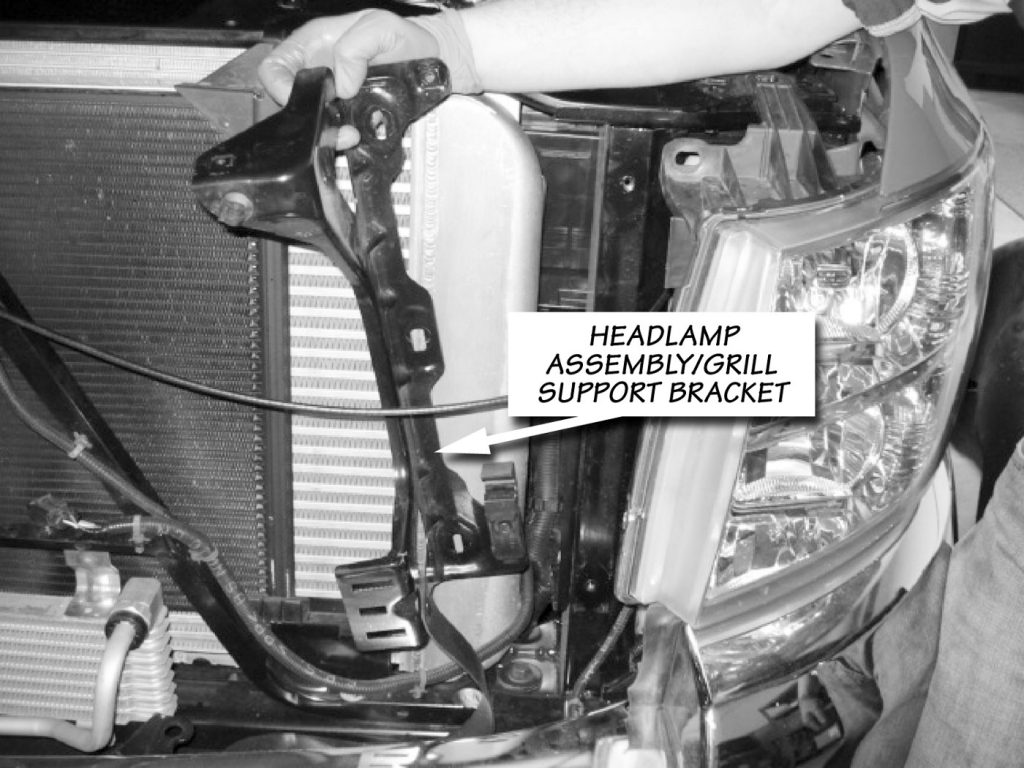
Step 9
Remove the headlamp mounting structure on the driver and passenger side of the vehicle shown in Figure 4. There are six 10mm bolts, three per side. The retaining clip that attaches the hood latch cable to the support structure must also be removed on the driver’s side.
Step 10
Remove the two bolts that secure the intercooler to the upper radiator cross brace. Remove four 13mm bolts, two per side, that connect the intercooler to the radiator.
Step 11
Remove the low-pressure A/C condenser line from the line retainer attached to the upper fan shroud.
Step 12
Remove the two upper condenser mounting bolts that attach to the radiator cross brace.
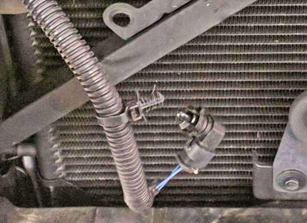
Step 13
Remove the ambient temp sensor. See Figure 5.
Step 14
Mark the location of the hood latch, disconnect the hood latch electrical connector, then remove the hood latch from the latch support. The latch is held in place by three bolts. It is not necessary to remove the cable from the latch, just place the latch and cable assembly out of the way.
Step 15
Remove the two bolts that attach the latch support to the radiator cross brace and the four lower attachment bolts (two per side). The two bolts that attach the upper support to the radiator cross brace are accessed from the engine compartment side of the vehicle.
Step 16
Remove oil cooler mounting bolts.
Step 17
Remove the power steering cooler mounting bolts.
Step 18
Pull the air conditioning condenser out of it’s lower mounts.
Step 19
Remove the six bolts (three per side) that secure the radiator cross brace. The bolts are on the bottom side at each end of the support. Remove the cross brace from the vehicle.
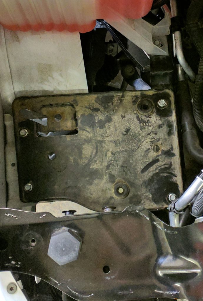
Step 20
Remove mounting tray under airbox and corner brace. See Figures 6 & 7.
Section 3: Installation of Banks Intercooler
Step 21
Loosen the driver side boost tube hose clamps. Remove the boost tube from the charge air cooler (CAC).
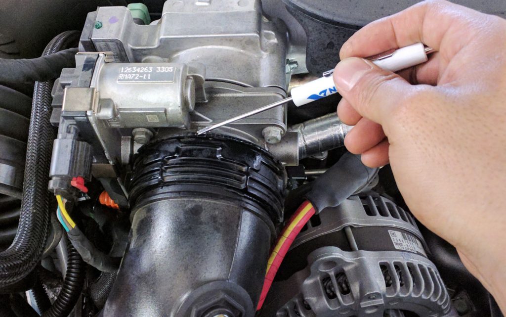
Step 22
Remove the passenger side boost tube and intake air temperature sensor. Use a small screwdriver to rotate the retaining ring to release the boost tube. See Figure 8.
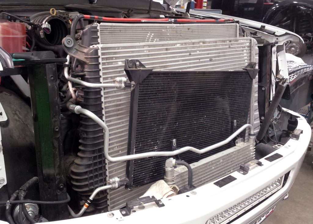
Step 23
At this point, the charge air cooler is ready for removal. Shown in Figure 9.
Step 24
Remove the charge air cooler from the vehicle. Check that the lower mounting peg grommets are removed from the stock intercooler and place to the side. The lower rubber grommet will be transferred to the Banks intercooler.
Step 25
Loosen the driver side boost tube hose clamps from the turbo outlet. Remove the stock driver’s side boost tube from the vehicle.
Step 26
Locate the supplied Banks charge air cooler and transfer both top and bottom rubber grommets and corresponding metal sleeve into position on the Banks charge air cooler.
Step 27
Install the Banks CAC into the vehicle. Align the lower CAC mounting pegs with the rubber mounts in the vehicle’s frame. There is a significant amount of play in the rubber mounts that can allow them to be aligned with the CAC as required.
Step 28
Reinstall the radiator cross brace. Leave the attachment bolts loose to aid in aligning the CAC with the support.
Step 29
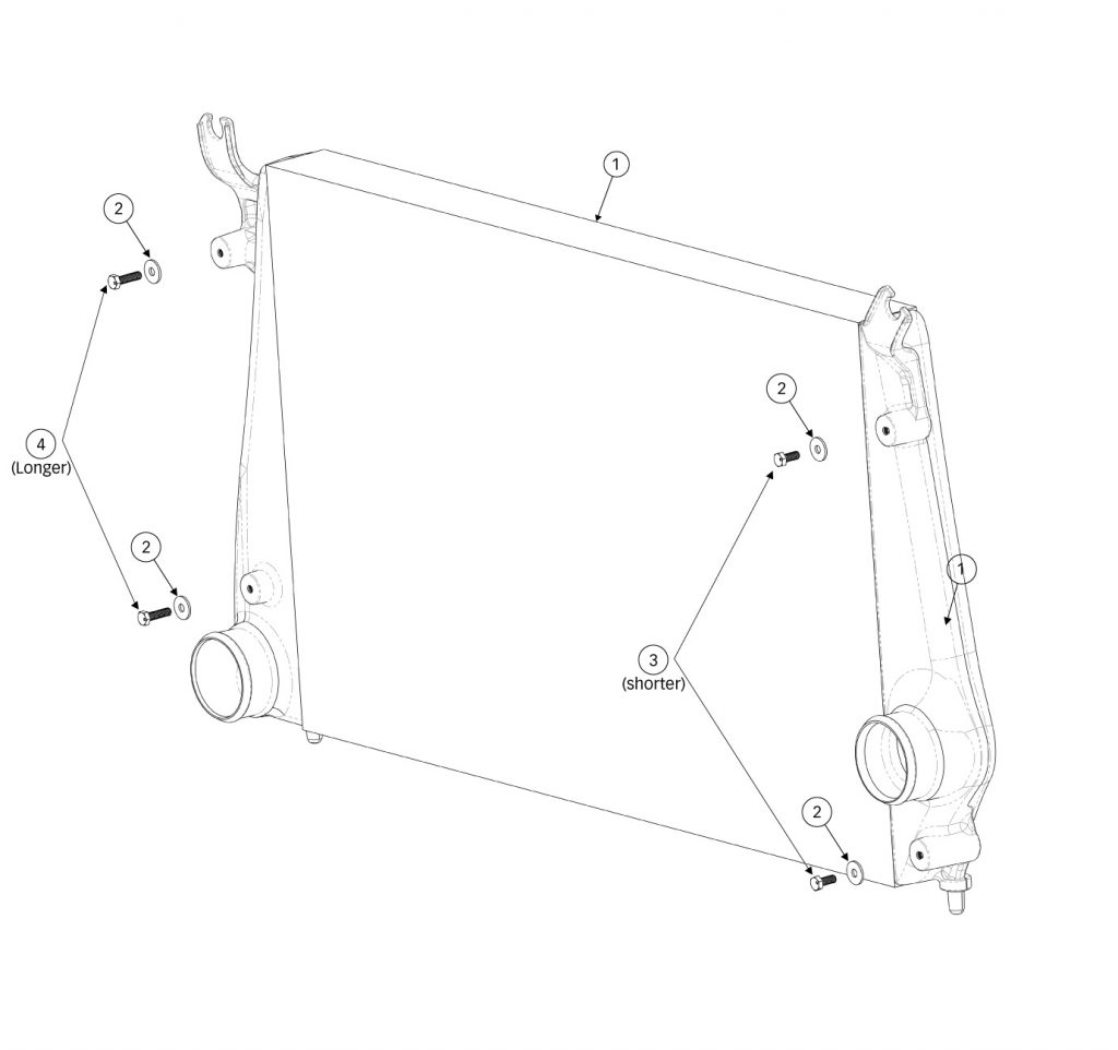
Reinstall the radiator onto CAC. Secure the radiator to the Banks CAC with supplied bolts washers supplied in the Banks system. Tighten to 15-18 ft-lbs.
Note: Use the 20 mm long bolts on the passenger side, and the 30 mm bolts on the driver’s side.
Note: Install the passenger side bolts first and then install driver side bolts. It may be helpful to use a pry bar or similar to assist in aligning the screw holes between the radiator and the Banks charge air cooler.
Step 30
Install the upper CAC attachment bolts that were previously removed. There is enough play in the lower mounting pads, that the CAC can be positioned to align with the upper cross brace. Tighten the bolts.
Step 31
Check that the engine-cooling fan can freely spin without contacting the lower fan shroud. If the fan contacts the shroud, the shroud must be realigned with the radiator.
Step 32
Tighten the six radiator-cross brace bolts to 80 in-lbs. Install the diagonal fender support brace and tighten the bolts.
NOTE: Before slipping any boost tubes and the corresponding hoses, into
position, ensure that all connection ends are clean and free of any oil residue and contaminate. Clean compressor outlet and all connection points with a non-oil based solvent such as Acetone, Mineral Spirits, Denatured Alcohol, or Lacquer Thinner. Read and follow the manufactures operation instruction for non-oil based solvent cleaner
NOTE: The a/c line that runs near the intake manifold will need to be bent downward to provide clearance for the boost tube. The a/c line can be bent by placing a wooden block on the a/c line, then lightly tapping the block with a hammer.
Step 33
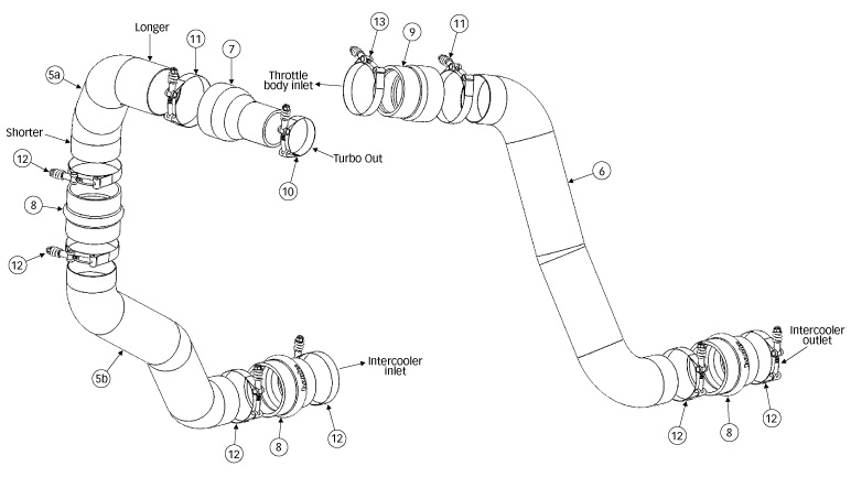
Install hump hose (Item #8) onto the Banks intercooler inlet with clamps (Item #12) oriented as shown in Figure 10.
Step 34
Insert the lower driver’s side boost tube (item #5b) through the fender well and into the intercooler hump hose (item #8).
Step 35
Install hump hose (item #8) onto the lower boost tube with clamps (item #12).
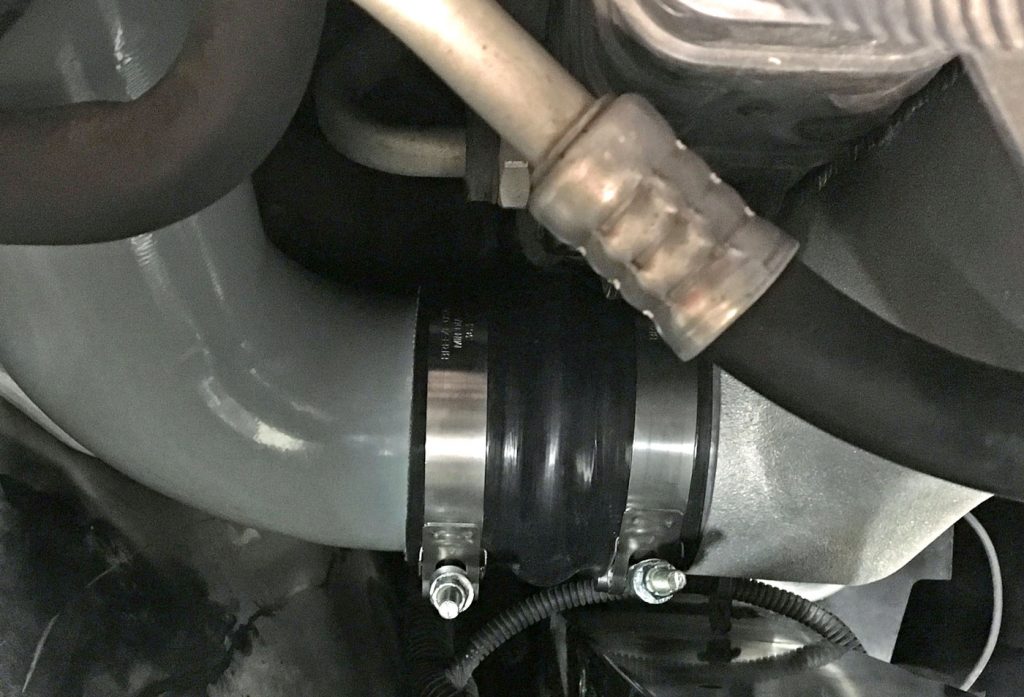
Step 36
Install transition hose (item #7) onto the turbo outlet with clamp (items #10 & 11).
Step 37
Insert the upper driver’s side boost tube (item #5) into the turbo outlet transition hose (item #7) and into the hump hose (item #8) connecting to the lower boost tube.
Step 38
Check for clearances around the boost tube and tighten all T-bolt clamps to 5ft lbs.
Step 39
Relocate ECU harness. The passenger side boost tube may pinch the orange ECU harness once installed (as seen in Figure 11).
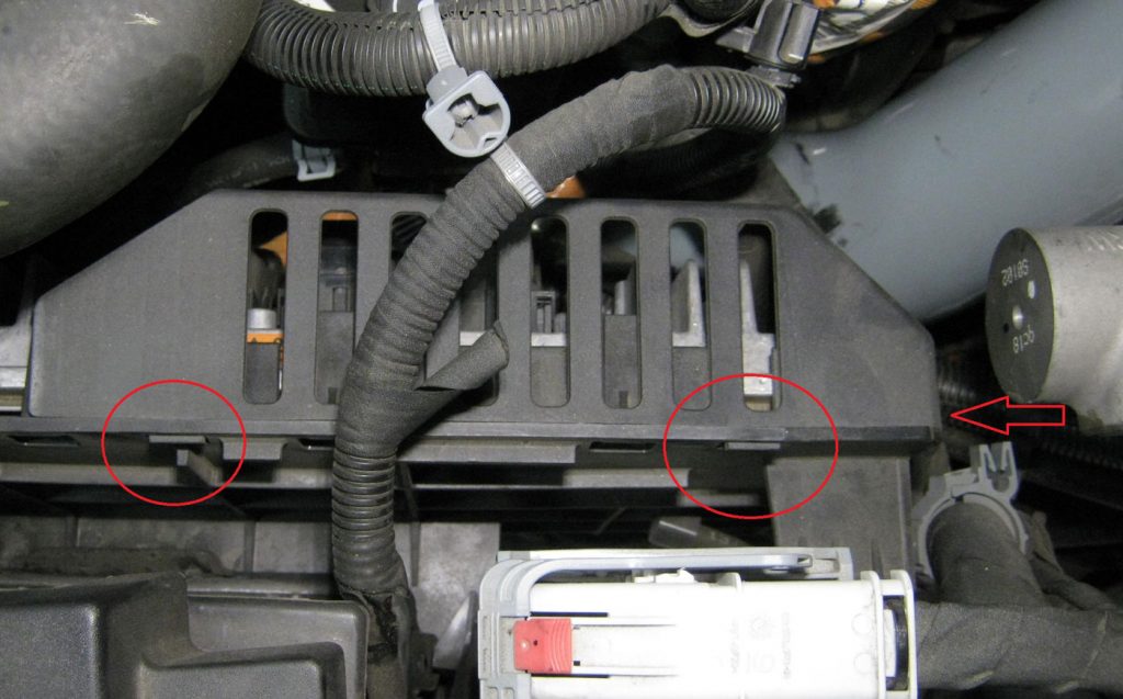
Step 40
Unhook the two clips on the top, and one on the side, that hold the protective baffle above the ECU connections as shown in Figure 11.
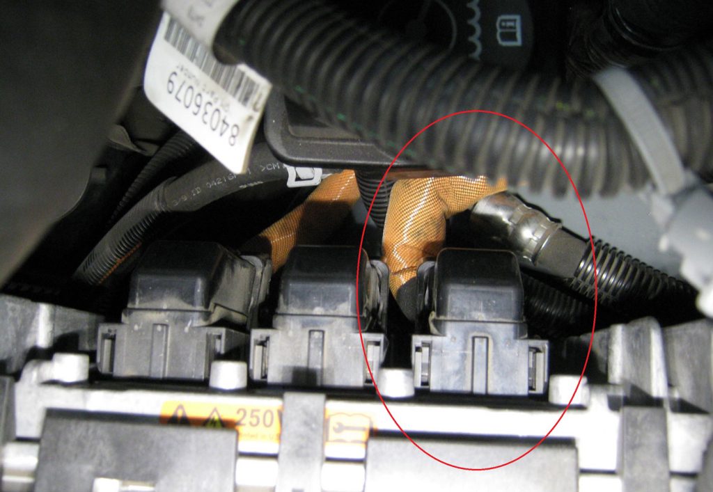
Step 41
On the innermost connector, slide the red locking tab up and swing the connection hinge up and out to release the connector. Reroute orange harness line above the high-pressure line and black wire loom. Reconnect the ECU and protective baffle. See Figure 12.
Step 42
Install hump hose (Item #8) onto the Banks intercooler outlet with clamps (Item #12) oriented as shown in Figure 13.
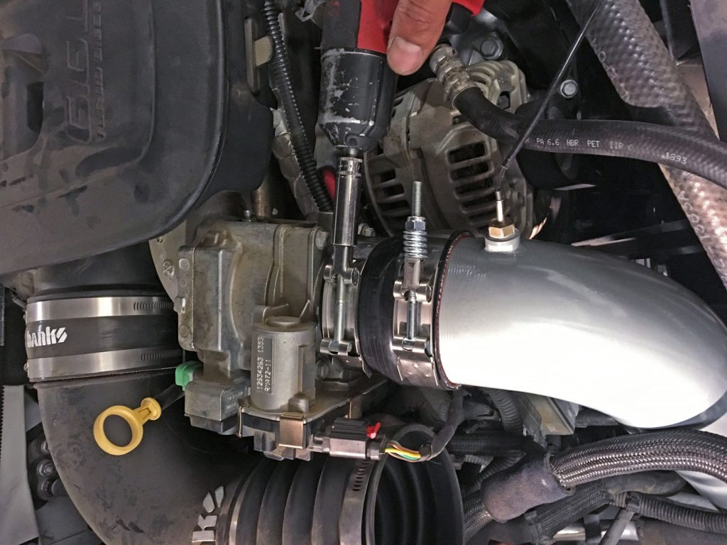
Step 43
Install transition hose (Item #9) onto the throttle body inlet with clamps (Items #11 and 13) as shown in Figure 14.
Step 44
Insert the passenger side boost tube and tighten all clamps to 5ft. lbs.
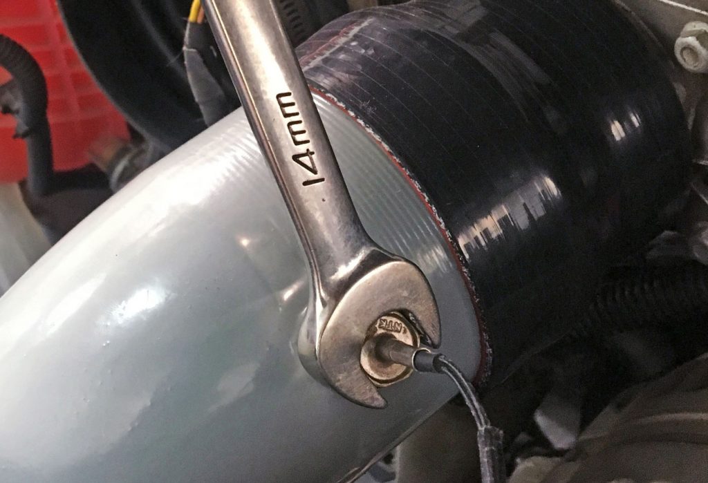
Step 45
Re-install the intake air temperature sensor as shown in Figure 15.
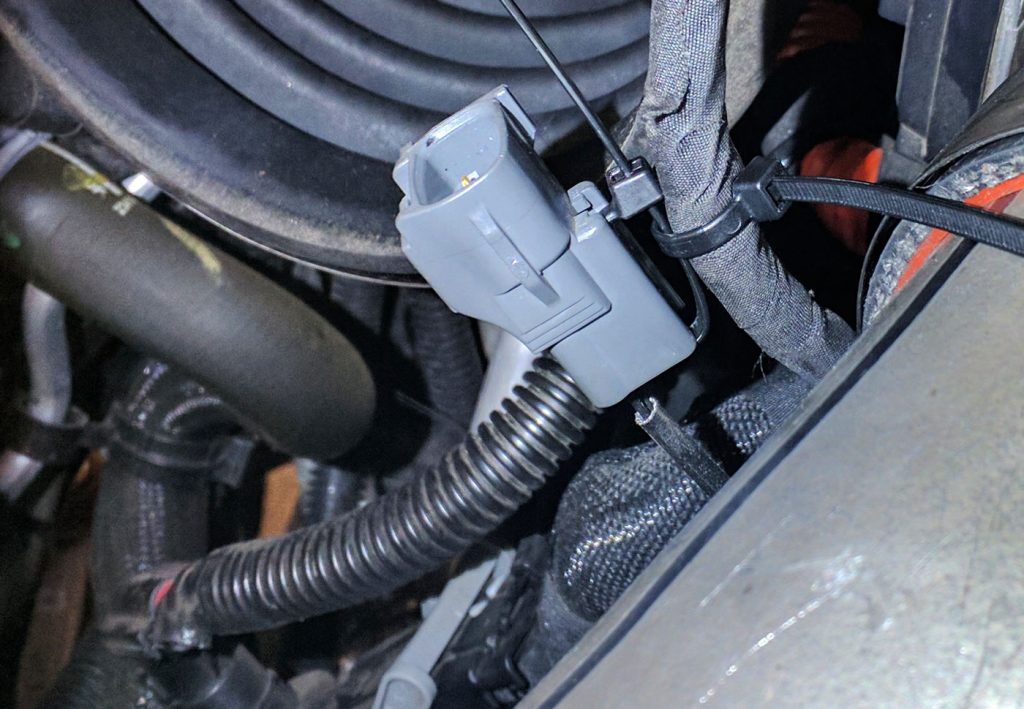
Step 46
Secure IAT sensor harness as shown in Figure 16.
Step 47
Install the a/c condenser, ambient temp sensor, oil cooler, power steering cooler, their tighten it’s upper mounting bolts to 80 in-lbs.
Step 48
Install the latch support. Tighten it’s attachment bolts to 80 in-lbs.
Step 49
Install the hood latch. Position it so that it aligns with the marks that were previously made on the latch support prior to its removal. Tighten bolt to 80 in-lbs.
Step 50
Install the driver and passenger side headlamp support structures. Tighten the screws to 80 in-lbs.
Step 51
Install the electrical connectors to the headlamp assembly. Install the headlamp assemblies and trim panels.
Step 52
Install the grill by snapping in the tabs into the retainer clips.
Step 53
Install the upper grill baffle and secure with the push-in retainers that were previously removed. The push-in retainers that secure the grill baffle are secured by inserting the retainer with the center pin pulled out. Once the retainer is inserted, press the center pin down to secure the retainer.
Step 54
Install the mounting tray, corner brace, and air box assembly. Install the air duct on the turbocharger inlet and tighten its hose clamp.
Step 55
Install the driver side and passenger side fender well. The charge air temperature before the CAC approaches 400°F at full load. So, take care to route wiring away from the driver side boost tube and re-install the factory wire retainers on the fender well cover.
Step 56
Re-install the connector on the MAF sensor at the airbox assembly.
Step 57
Re-connect the ground cables on both batteries.
Step 58
Road test the truck ensuring there are no leaks. Be sure to re-check all the connections and re-tighten everything at least twice in the first three days or 100 miles.